CN114319343A - Construction method of enlarged head anchor cable for expansive soil area - Google Patents
Construction method of enlarged head anchor cable for expansive soil area Download PDFInfo
- Publication number
- CN114319343A CN114319343A CN202210007426.4A CN202210007426A CN114319343A CN 114319343 A CN114319343 A CN 114319343A CN 202210007426 A CN202210007426 A CN 202210007426A CN 114319343 A CN114319343 A CN 114319343A
- Authority
- CN
- China
- Prior art keywords
- anchor cable
- anchor
- enlarged head
- expansive soil
- grouting
- Prior art date
- Legal status (The legal status is an assumption and is not a legal conclusion. Google has not performed a legal analysis and makes no representation as to the accuracy of the status listed.)
- Pending
Links
- 239000002689 soil Substances 0.000 title claims abstract description 49
- 238000010276 construction Methods 0.000 title claims abstract description 29
- 239000004568 cement Substances 0.000 claims abstract description 27
- 239000002002 slurry Substances 0.000 claims abstract description 18
- 239000008399 tap water Substances 0.000 claims abstract description 15
- 235000020679 tap water Nutrition 0.000 claims abstract description 15
- 239000007921 spray Substances 0.000 claims abstract description 13
- 238000005507 spraying Methods 0.000 claims abstract description 11
- 238000005553 drilling Methods 0.000 claims abstract description 7
- 238000004140 cleaning Methods 0.000 claims abstract description 6
- 229910000831 Steel Inorganic materials 0.000 claims description 84
- 239000010959 steel Substances 0.000 claims description 84
- 238000000034 method Methods 0.000 claims description 18
- XLYOFNOQVPJJNP-UHFFFAOYSA-N water Substances O XLYOFNOQVPJJNP-UHFFFAOYSA-N 0.000 claims description 17
- 238000004873 anchoring Methods 0.000 abstract description 9
- 238000003466 welding Methods 0.000 description 8
- 230000000694 effects Effects 0.000 description 6
- 230000002093 peripheral effect Effects 0.000 description 6
- 238000010586 diagram Methods 0.000 description 4
- 238000011160 research Methods 0.000 description 4
- 238000010521 absorption reaction Methods 0.000 description 3
- 238000009412 basement excavation Methods 0.000 description 3
- 230000008901 benefit Effects 0.000 description 3
- 238000009434 installation Methods 0.000 description 3
- 238000007664 blowing Methods 0.000 description 2
- 238000012360 testing method Methods 0.000 description 2
- 235000017166 Bambusa arundinacea Nutrition 0.000 description 1
- 235000017491 Bambusa tulda Nutrition 0.000 description 1
- 241001330002 Bambuseae Species 0.000 description 1
- 235000015334 Phyllostachys viridis Nutrition 0.000 description 1
- 239000011425 bamboo Substances 0.000 description 1
- 230000009286 beneficial effect Effects 0.000 description 1
- 230000007547 defect Effects 0.000 description 1
- 238000013461 design Methods 0.000 description 1
- GUJOJGAPFQRJSV-UHFFFAOYSA-N dialuminum;dioxosilane;oxygen(2-);hydrate Chemical compound O.[O-2].[O-2].[O-2].[Al+3].[Al+3].O=[Si]=O.O=[Si]=O.O=[Si]=O.O=[Si]=O GUJOJGAPFQRJSV-UHFFFAOYSA-N 0.000 description 1
- 238000006073 displacement reaction Methods 0.000 description 1
- 238000005516 engineering process Methods 0.000 description 1
- 238000002474 experimental method Methods 0.000 description 1
- 230000002349 favourable effect Effects 0.000 description 1
- 229910052900 illite Inorganic materials 0.000 description 1
- 229910052500 inorganic mineral Inorganic materials 0.000 description 1
- 239000011707 mineral Substances 0.000 description 1
- 229910052901 montmorillonite Inorganic materials 0.000 description 1
- VGIBGUSAECPPNB-UHFFFAOYSA-L nonaaluminum;magnesium;tripotassium;1,3-dioxido-2,4,5-trioxa-1,3-disilabicyclo[1.1.1]pentane;iron(2+);oxygen(2-);fluoride;hydroxide Chemical compound [OH-].[O-2].[O-2].[O-2].[O-2].[O-2].[F-].[Mg+2].[Al+3].[Al+3].[Al+3].[Al+3].[Al+3].[Al+3].[Al+3].[Al+3].[Al+3].[K+].[K+].[K+].[Fe+2].O1[Si]2([O-])O[Si]1([O-])O2.O1[Si]2([O-])O[Si]1([O-])O2.O1[Si]2([O-])O[Si]1([O-])O2.O1[Si]2([O-])O[Si]1([O-])O2.O1[Si]2([O-])O[Si]1([O-])O2.O1[Si]2([O-])O[Si]1([O-])O2.O1[Si]2([O-])O[Si]1([O-])O2 VGIBGUSAECPPNB-UHFFFAOYSA-L 0.000 description 1
- 239000002245 particle Substances 0.000 description 1
- 125000006850 spacer group Chemical group 0.000 description 1
Images


Landscapes
- Piles And Underground Anchors (AREA)
Abstract
The invention belongs to the technical field of anchor cables, and discloses a construction method of an anchor cable with an expanded head for an expansive soil area, which aims to solve the problem that the anchoring force of the anchor cable is reduced due to the reduction of the mechanical property of rainwater in the expansive soil. The invention comprises the following steps: (1) drilling a hole to a set elevation; (3) placing a rotary spray head of the high-pressure rotary spray machine at the upper end of the enlarged head section, and reaming by using tap water by using the high-pressure rotary spray head; (4) placing a rotary nozzle of the high-pressure rotary spraying machine at the bottom of the anchor hole and reaming by using cement slurry; (5) cleaning holes and putting anchor cables; (6) grouting, tensioning and locking to finish the construction of the anchor cable with the enlarged head. The invention avoids the problem of reduced anchoring force caused by reduced mechanical property caused by the expansion and softening of the expansive soil after rain.
Description
Technical Field
The invention belongs to the technical field of anchor cables, and particularly relates to a construction method of an anchor cable with an expanded head for an expansive soil area.
Background
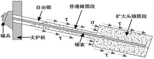
The anchor cable is one of important means for controlling foundation pit deformation in foundation pit supporting engineering, and is generally applied to deep foundation pit supporting engineering because the supporting mode is favorable for earth excavation and underground structure construction, the construction period is greatly shortened, and the construction cost is reduced. In recent years, the expanded head anchor cable newly appeared in the field has own unique advantages, and has led a great deal of research of relevant scholars. From the perspective of mechanical mechanism, the pulling resistance of the conventional anchor cable (as shown in fig. 1) mainly originates from the lateral resistance of the anchor body and the soil body, and belongs to a friction-type anchor cable, while the pulling resistance of the enlarged head anchor cable (as shown in fig. 2) mainly comprises two parts, namely the lateral resistance of the anchor body side wall of the common anchor section, the enlarged head side wall and the soil body, and the end resistance of the soil body to the end part of the enlarged head, which belong to a friction-end-bearing type anchor cable. The study has conducted a lot of field tests to verify the advantage of the uplift resistance of the enlarged head anchor cable under the same conditions, and the test results prove that the ultimate uplift bearing capacity of the enlarged head anchor cable is about 1-3 times that of a common anchor cable, and the larger the area with the better soil condition, the larger the uplift factor, and the smaller the displacement discrete type of the anchor cable. The process has been successfully applied to a plurality of large-scale deep foundation pit supporting projects, obtains ideal engineering value, has simple construction, high efficiency and good construction quality compared with the common anchor cable construction process, greatly improves the pulling resistance, has low construction cost, can overcome complicated soil conditions, and has wide application range. However, the application and research of the enlarged head anchor cable in the expansive soil area are relatively few, and the construction method and theoretical calculation of the enlarged head anchor cable have certain defects, so that the deep research of the working mechanism of the enlarged head anchor cable has higher application value for the application of the enlarged head anchor cable in engineering.
The anchoring force of the conventional common tension anchor cable mainly depends on the length of an effective anchoring section and the frictional resistance between an anchoring body and a soil layer, the mechanical index of expansive soil in a natural state without water absorption is better, and once the expansive soil meets water, the mechanical index of the expansive soil is rapidly reduced because montmorillonite and illite mineral particles have extremely strong water absorption, a soil body expands after water absorption and becomes soft gradually, even becomes a flow plastic shape, the soil body begins to slump, the soil pressure is increased, and the anchor rod loses the anchoring force. In view of the above, the research on the application of the new hole-expanding anchoring technology to the expansive soil stratum is particularly urgent.
Disclosure of Invention
The invention provides a construction method of an anchor cable with an expanded head for an expansive soil area, aiming at solving the problem that the mechanical property of the expansive soil rainwater is reduced to reduce the anchoring force of the anchor cable, and avoiding the problem that the mechanical property is reduced to reduce the anchoring force caused by the expansion and softening of the expansive soil rainwater; meanwhile, the invention can also improve the pulling resistance of a single anchor cable, thereby reducing the pile diameter of the single anchor cable and effectively reducing the construction period and the construction cost.
In order to solve the technical problem, the technical scheme adopted by the invention is as follows:
a construction method of an anchor cable with an enlarged head for an expansive soil area is characterized by comprising the following steps:
(1) determining the position of each anchor cable;
(2) drilling to a set elevation;
(3) placing a rotary spray head of a high-pressure rotary spraying machine at the upper end of the expansion head section, spraying tap water by the high-pressure rotary spray head along the direction from top to bottom, and then reaming the anchor hole of the expansion head section along the sequence from bottom to top; repeatedly reaming for 2-3 times by using tap water through the high-pressure rotary nozzle;
(4) placing a rotary spray head of the high-pressure rotary spraying machine at the bottom of the anchor hole, and spraying cement slurry by the high-pressure rotary spray head to ream the anchor hole of the enlarged head section again along the direction from bottom to top to form the enlarged head section;
(5) cleaning holes and putting anchor cables;
(6) grouting, tensioning and locking to finish the construction of the anchor cable with the enlarged head.
In some embodiments, the grouting in step (6) comprises a first grouting and a second grouting, the second grouting is performed after the first grouting is initially set, and the pressure of the second grouting is greater than that of the first grouting.
In some embodiments, the water-cement ratio of the cement slurry is 1:1 when the rotary nozzle of the high-pressure rotary sprayer is used for reaming by using the cement slurry.
In some embodiments, when the rotary sprayer of the high-pressure rotary sprayer is used for reaming by using tap water, the up-and-down running speed of the rotary sprayer is 15-20cm/min, and the pressure of the tap water is 28-32 MPa.
In some embodiments, the anchor cable includes a positioning steel bar and at least three steel strands surrounding the periphery of the positioning steel bar, a first mounting plate is installed at the top end and the bottom end of the positioning steel bar, a second mounting plate is further installed on the positioning steel bar, the peripheries of the positioning steel bar are sequentially and alternately arranged on the first mounting plate and the second mounting plate at intervals, the diameter of the first mounting plate is larger than that of the second mounting plate, a plurality of through holes for the steel strands to pass through are formed in the second mounting plate, and grooves for the steel strands to pass through are formed in the outer circumferential wall of the first mounting plate.
In some embodiments, a through hole for passing a positioning steel bar is formed in the center of each of the first mounting plate and the second mounting plate, an open threaded cylinder is mounted on each of the upper side and the lower side of the through hole, a locking nut is provided on each open threaded cylinder, and the positioning steel bar passes through the through hole and is fastened through the matching of the open threaded cylinder and the locking nut.
In some embodiments, the middle parts of the first installation disc and the second installation disc are provided with a plurality of openings for cement slurry to pass through.
In some embodiments, the top end of the positioning steel bar is screwed with the first mounting plate, the bottom end of the positioning steel bar is fixedly connected with the first mounting plate, and the top end of the positioning steel bar is flush with the upper end surface of the first mounting plate.
In some embodiments, at least two of the first mounting discs each have an outer diameter that is adapted to the inner diameter of the non-enlarged head section of the anchor bore.
Compared with the prior art, the invention has the following beneficial effects:
according to the construction method of the enlarged head anchor cable for the expansive soil area, disclosed by the invention, the clear water is firstly utilized for carrying out primary hole expansion in the anchor hole construction process, so that the expansive soil is firstly sprayed by the clear water, on one hand, the expansive soil is enabled to absorb water and soften in advance, the hole expansion efficiency is improved by utilizing the characteristic (gradually softening and even flowing plastic) of the expansive soil after absorbing water, on the other hand, the expansive soil is enabled to absorb water and soften in advance, the problem that the expansive soil is softened again when meeting water in the subsequent construction process is avoided, and the pulling resistance of the anchor cable is ensured. And then, reaming is carried out by utilizing cement paste, the cement paste which is sprayed out by the high-pressure nozzle in a rotating mode impacts expansive soil under the action of pressure to ream, and then the cement paste and the expansive soil form a whole to complete reaming operation of the expanded head section of the anchor hole.
In the using process of the anchor cable, the positioning steel bars are used as supporting points of the whole anchor cable, the first mounting disc and the second mounting disc are fastened on the positioning steel bars, and then the first mounting disc and the second mounting disc are used for positioning peripheral steel strands, so that on one hand, the uniformity of the distribution of the steel strands is ensured, and the uniformity of the stress of the anchor cable is improved; secondly, the peripheral steel strands enable the cross-sectional area of the anchor cable to be changed continuously under the action of the first mounting disc and the second mounting disc, the contact area of the anchor cable and injected cement paste is increased, and the pulling resistance of a single anchor cable is improved; finally, the positioning steel bars can also improve the rigidity of the anchor cable, ensure the straightness of the anchor cable implanted into the anchor hole, solve the problem that the anti-pulling capacity of the anchor cable is reduced due to poor straightness of the anchor cable in the anchor hole in the prior art, and improve the anti-pulling capacity of the single-pile anchor cable.
Compare simultaneously in prior art adoption in the peripheral welding centering support's of anchor rope mode, avoided the problem of the anchor rope damage that the welding leads to on the one hand, the card through first mounting disc and second mounting disc is held the effect and is avoided the welding and lead to the problem that deformation and precision are not high. On the other hand, through the effect of holding of the card of first mounting disc and second mounting disc for when carrying out stretch-draw locking to the anchor rope, each steel strand wires can carry out appropriate slip on first mounting disc and second mounting disc, thereby makes the steel strand wires atress more even. In the prior art, the steel strand is fixed with the centering support in a welding mode, and when the steel strand is tensioned and locked, under the action of the centering support (in a stability grouting body), stress on each section of the steel strand is uneven, so that tension applied to the steel strand is not evenly transmitted to each position of the steel strand. When the anchor cable is used, when the steel strand is tensioned, the steel strand can slide on the first mounting disc and the second mounting disc, so that stress on each position of the whole steel strand is more uniform, acting force transmitted to a grouting body is dispersed uniformly, the problem of cracks caused by nonuniform stress of the grouting body is avoided, and the durability of the anchor cable is improved.
Drawings
Fig. 1 is a schematic diagram of the stress of a conventional anchor cable;
fig. 2 is a schematic force diagram of a conventional anchor cable with enlarged head;
fig. 3 is a schematic structural view of the anchor cable with enlarged head according to the present invention;
FIG. 4 is a schematic structural diagram of an embodiment of a first mounting plate of the present invention;
FIG. 5 is a schematic structural diagram of an embodiment of a second mounting plate of the present invention;
FIG. 6 is a side view of another embodiment of the second mounting plate of the present invention;
the labels in the figure are: 1. positioning steel bar, 2, first mounting disc, 21, perforating hole, 22, recess, 23, opening, 3, second mounting disc, 31, through-hole, 32, opening screw cylinder, 33, lock nut, 4, steel strand wires.
Detailed Description
The present invention will be further described with reference to the following examples, which are intended to illustrate only some, but not all, of the embodiments of the present invention. Based on the embodiments of the present invention, other embodiments used by those skilled in the art without any creative effort belong to the protection scope of the present invention.
In the description of the present invention, it should be noted that the terms "center", "upper", "lower", "left", "right", "vertical", "horizontal", "inner", "outer", etc., indicate orientations or positional relationships based on the orientations or positional relationships shown in the drawings, and are only for convenience of description and simplicity of description, but do not indicate or imply that the device or element being referred to must have a particular orientation, be constructed and operated in a particular orientation, and thus, should not be construed as limiting the present invention; the terms "first," "second," and "third" are used for descriptive purposes only and are not to be construed as indicating or implying relative importance; furthermore, unless expressly stated or limited otherwise, the terms "mounted," "connected," and "connected" are to be construed broadly, as they may be fixedly connected, detachably connected, or integrally connected, for example; may be a mechanical connection; may be directly connected or indirectly connected through an intermediate. To those of ordinary skill in the art, the specific meanings of the above terms in the present invention can be understood in conjunction with specific situations.
With reference to the attached drawings, the construction method of the anchor cable with the enlarged head for the expansive soil area comprises the following steps:
(1) determining the position of each anchor cable;
(2) drilling to form a hole to a set elevation, namely drilling to form an anchor hole with equal diameter; wherein, anchor cable construction and earth excavation are carried out until the height of the anchor cable is 1.0m below the elevation (namely, excavation is carried out on the poured support pile firstly, and the height of the anchor cable is 1.0m below the elevation of the anchor cable standard top), then drilling of an anchor hole is started, and drilling of the anchor hole can be carried out by adopting a down-the-hole hammer;
(3) placing a rotary sprayer of a high-pressure rotary sprayer at the upper end of an expansion head section (namely, the upper section of an anchor hole is an equal-diameter anchor hole, and the lower section of the anchor hole is subjected to hole expansion to form the expansion head section), wherein tap water sprayed by the high-pressure rotary sprayer is expanded from top to bottom, and then the anchor hole of the expansion head section is subjected to hole expansion along the sequence from bottom to top; repeatedly reaming for 2-3 times by using tap water through the high-pressure rotary nozzle; when the high-pressure rotary sprayer performs reaming by using tap water, reaming is performed along the direction from top to bottom each time, and then reaming is performed along the direction from bottom to top, namely when the high-pressure rotary sprayer performs reaming by using the tap water, each circulation is to perform reaming from top to bottom and then perform reaming from bottom to top;
(4) placing a rotary spray head of the high-pressure rotary spraying machine at the bottom of the anchor hole, and spraying cement slurry by the high-pressure rotary spray head to ream the anchor hole of the enlarged head section again along the direction from bottom to top to form the enlarged head section;
(5) cleaning holes and putting anchor cables; in the specific implementation process, because the anchor hole is filled with more slurry, hole cleaning operation is required to be carried out to ensure that the anchor cable is normally placed, the hole cleaning operation is mainly carried out by adopting high-pressure air, namely after hole expansion is finished, the end part of a drill rod of the anchor cable stays to the bottom of the hole, the high-pressure air is used for blowing out muck, the drill rod is lifted back and forth in the blowing process, and most of muck and slurry can be cleaned out;
(6) grouting, tensioning and locking to finish the construction of the anchor cable with the enlarged head. When the anchor cable is stretched, the steel strands are stretched one by one, so that the steel strands are straightened one by one, and then the whole steel strand is stretched integrally.
Through experiments, taking the foundation pit supporting project of the novel community No. 4 plot project of the forest trees in Yibin city, Sichuan province as an example, the depth of the foundation pit is about 10m, the original design single-row supporting pile can not meet the safety requirement, the safety requirement of the foundation pit can be met only by adopting double-row piles or anchor piles, and the conventional tension type anchor cable is low in pulling force and poor in stability. After the reaming anchor cable disclosed by the invention is adopted to improve the pulling resistance of a single anchor cable, the pile diameter and the pile number can be properly reduced, the economical efficiency is better, the reliability is better, and certain economic benefit can be better brought.
In some embodiments, the grouting in step (6) comprises a first grouting and a second grouting, the second grouting is performed after the first grouting is initially set, and the pressure of the second grouting is greater than that of the first grouting. The pressure during the first grouting is less than that of the second grouting, preferably, the pressure during the first grouting is 0.4-0.6MPa, and the pressure during the second grouting is 1.8-2.3 MPa.
In some embodiments, the water-cement ratio of the cement slurry is 1:1 when the rotary nozzle of the high-pressure rotary sprayer is used for reaming by using the cement slurry. When the cement slurry is used for reaming, the pressure of the cement slurry is 30-35 MPa.
In some embodiments, when the rotary sprayer of the high-pressure rotary sprayer is used for reaming by using tap water, the up-and-down running speed of the rotary sprayer is 15-20cm/min, and the pressure of the tap water is 28-32 MPa.
In some embodiments, the anchor cable includes a positioning steel bar 1 and at least three steel strands 4 surrounding the periphery of the positioning steel bar 1, first mounting discs 2 are installed at the top end and the bottom end of the positioning steel bar 1, second mounting discs 3 are further installed on the positioning steel bar 1, the peripheries of the positioning steel bars 1 are sequentially and alternately arranged on the first mounting discs 2 and the second mounting discs 3, the diameter of each first mounting disc 2 is larger than that of each second mounting disc 3, a plurality of through holes 31 for the steel strands 4 to pass through are formed in each second mounting disc 3, and grooves 22 for the steel strands 4 to pass through are formed in the outer circumferential wall of each first mounting disc 2. Wherein, the internal diameter of through-hole 31 and recess 22 slightly is greater than the external diameter of steel strand wires 4 to make steel strand wires 4 can slide in through-hole and recess, so that when later stage carries out the stretch-draw to steel strand wires, each steel strand wires can move and adjust under the effect of pulling force, so that whole steel strand wires all are in the state of straining straightly, thereby make the steel strand wires atress even.
In some embodiments, a through hole 21 for passing the positioning steel bar 1 is opened in the center of the first mounting plate 2 and the second mounting plate 3, an open threaded cylinder 32 is installed on both the upper side and the lower side of the through hole 21, a lock nut 33 is provided on the open threaded cylinder 32, and the positioning steel bar 1 passes through the through hole 21 and is fastened by the cooperation of the open threaded cylinder 32 and the lock nut 33. Wherein, can be convenient for install first mounting disc and second mounting disc on spacer bar 1 through the cooperation of opening thread section of thick bamboo and lock nut. In some embodiments, the first mounting plate and the second mounting plate may be screwed with the positioning steel bars.
In some embodiments, the middle portions of the first and second installation plates 2 and 3 are provided with a plurality of openings 23 for cement slurry to pass through, so as to ensure that cement slurry can smoothly enter the anchor holes and form a grouting body during grouting.
In some embodiments, the top end of the positioning steel bar 1 is in threaded connection with the first mounting disc 2, the bottom end of the positioning steel bar 1 is fixedly connected with the first mounting disc 2, and the top end of the positioning steel bar 1 is flush with the upper end face of the first mounting disc 2, that is, the top end of the positioning steel bar 1 does not extend out of the uppermost first mounting disc 2.
In some embodiments, the outer diameters of at least two first mounting plates in each first mounting plate are matched with the inner diameter of the non-enlarged head section of the anchor hole, that is, the diameters of the two first mounting plates in each first mounting plate are matched with the bore diameter of the non-enlarged head section of the anchor hole, so that the positioning effect of the anchor cable in the anchor hole can be realized by directly using the two first mounting plates 1.
According to the construction method of the enlarged head anchor cable for the expansive soil area, disclosed by the invention, the clear water is firstly utilized for carrying out primary hole expansion in the anchor hole construction process, so that the expansive soil is firstly sprayed by the clear water, on one hand, the expansive soil is enabled to absorb water and soften in advance, the hole expansion efficiency is improved by utilizing the characteristic (gradually softening and even flowing plastic) of the expansive soil after absorbing water, on the other hand, the expansive soil is enabled to absorb water and soften in advance, the problem that the expansive soil is softened again when meeting water in the subsequent construction process is avoided, and the pulling resistance of the anchor cable is ensured. And then, reaming is carried out by utilizing cement paste, the cement paste which is sprayed out by the high-pressure nozzle in a rotating mode impacts expansive soil under the action of pressure to ream, and then the cement paste and the expansive soil form a whole to complete reaming operation of the expanded head section of the anchor hole.
In the using process of the anchor cable, the positioning steel bars are used as supporting points of the whole anchor cable, the first mounting disc and the second mounting disc are fastened on the positioning steel bars, and then the first mounting disc and the second mounting disc are used for positioning peripheral steel strands, so that on one hand, the uniformity of the distribution of the steel strands is ensured, and the uniformity of the stress of the anchor cable is improved; secondly, the peripheral steel strands enable the cross-sectional area of the anchor cable to be changed continuously under the action of the first mounting disc and the second mounting disc, the contact area of the anchor cable and injected cement paste is increased, and the pulling resistance of a single anchor cable is improved; finally, the positioning steel bars can also improve the rigidity of the anchor cable, ensure the straightness of the anchor cable implanted into the anchor hole, solve the problem that the anti-pulling capacity of the anchor cable is reduced due to poor straightness of the anchor cable in the anchor hole in the prior art, and improve the anti-pulling capacity of the single-pile anchor cable.
Compare simultaneously in prior art adoption in the peripheral welding centering support's of anchor rope mode, avoided the problem of the anchor rope damage that the welding leads to on the one hand, the card through first mounting disc and second mounting disc is held the effect and is avoided the welding and lead to the problem that deformation and precision are not high. On the other hand, through the effect of holding of the card of first mounting disc and second mounting disc for when carrying out stretch-draw locking to the anchor rope, each steel strand wires can carry out appropriate slip on first mounting disc and second mounting disc, thereby makes the steel strand wires atress more even. In the prior art, the steel strand is fixed with the centering support in a welding mode, and when the steel strand is tensioned and locked, under the action of the centering support (in a stability grouting body), stress on each section of the steel strand is uneven, so that tension applied to the steel strand is not evenly transmitted to each position of the steel strand. When the anchor cable is used, when the steel strand is tensioned, the steel strand can slide on the first mounting disc and the second mounting disc, so that stress on each position of the whole steel strand is more uniform, acting force transmitted to a grouting body is dispersed uniformly, the problem of cracks caused by nonuniform stress of the grouting body is avoided, and the durability of the anchor cable is improved.
Claims (9)
1. A construction method of an anchor cable with an enlarged head for an expansive soil area is characterized by comprising the following steps:
(1) determining the position of each anchor cable;
(2) drilling to a set elevation;
(3) placing a rotary spray head of a high-pressure rotary spraying machine at the upper end of the expansion head section, spraying tap water by the high-pressure rotary spray head along the direction from top to bottom, and then reaming the anchor hole of the expansion head section along the sequence from bottom to top; repeatedly reaming for 2-3 times by using tap water through the high-pressure rotary nozzle;
(4) placing a rotary spray head of the high-pressure rotary spraying machine at the bottom of the anchor hole, and spraying cement slurry by the high-pressure rotary spray head to ream the anchor hole of the enlarged head section again along the direction from bottom to top to form the enlarged head section;
(5) cleaning holes and putting anchor cables;
(6) grouting, tensioning and locking to finish the construction of the anchor cable with the enlarged head.
2. The method for constructing an enlarged head anchor cable for expansive soil areas as claimed in claim 1, wherein the grouting in step (6) comprises a first grouting and a second grouting, the second grouting is performed after the first grouting is initially set, and the pressure of the second grouting is greater than that of the first grouting.
3. The method for constructing an enlarged head anchor cable for expansive soil areas as claimed in claim 1, wherein the water cement ratio of the cement slurry is 1:1 when the rotary nozzle of the high-pressure rotary sprayer is used for reaming by using the cement slurry.
4. The method for constructing an enlarged head anchor cable for expansive soil areas as claimed in claim 1, wherein when the rotary nozzle of the high-pressure rotary sprayer is used for reaming with tap water, the up-and-down running speed of the rotary nozzle is 15-20cm/min, and the pressure of the tap water is 28-32 MPa.
5. The method for constructing an enlarged footing anchor cable used in expansive soil areas as claimed in any one of claims 1 to 4, wherein the anchor cable comprises a positioning steel bar and at least three steel strands surrounding the positioning steel bar, the top end and the bottom end of the positioning steel bar are provided with first mounting discs, the positioning steel bar is further provided with second mounting discs, the first mounting discs and the second mounting discs are sequentially and alternately provided with the periphery of the positioning steel bar at intervals, the diameter of the first mounting discs is larger than that of the second mounting discs, the second mounting discs are provided with a plurality of through holes for the steel strands to pass through, and the outer circumferential wall of the first mounting discs is provided with grooves for the steel strands to pass through.
6. The method for constructing an enlarged head anchor cable for the expansive soil area as claimed in claim 5, wherein a through hole for passing the positioning steel bar is formed in the center of the first mounting plate and the second mounting plate, an open threaded cylinder is mounted on each of the upper side and the lower side of the through hole, a locking nut is arranged on the open threaded cylinder, and the positioning steel bar passes through the through hole and is fastened through the matching of the open threaded cylinder and the locking nut.
7. The method for constructing the anchor cable with the enlarged head for the expansive soil area as claimed in claim 5, wherein a plurality of openings for cement slurry to pass through are formed in the middle of the first mounting plate and the second mounting plate.
8. The method for constructing an enlarged head anchor cable for expansive soil areas as claimed in claim 5, wherein the top end of the positioning steel bar is screwed with the first mounting plate, the bottom end of the positioning steel bar is fixedly connected with the first mounting plate, and the top end of the positioning steel bar is flush with the upper end surface of the first mounting plate.
9. The method as claimed in claim 5, wherein the outer diameters of at least two first mounting plates of each first mounting plate are adapted to the inner diameter of the non-enlarged head section of the anchor hole.
Priority Applications (1)
| Application Number | Priority Date | Filing Date | Title |
|---|---|---|---|
| CN202210007426.4A CN114319343A (en) | 2022-01-06 | 2022-01-06 | Construction method of enlarged head anchor cable for expansive soil area |
Applications Claiming Priority (1)
| Application Number | Priority Date | Filing Date | Title |
|---|---|---|---|
| CN202210007426.4A CN114319343A (en) | 2022-01-06 | 2022-01-06 | Construction method of enlarged head anchor cable for expansive soil area |
Publications (1)
| Publication Number | Publication Date |
|---|---|
| CN114319343A true CN114319343A (en) | 2022-04-12 |
Family
ID=81025709
Family Applications (1)
| Application Number | Title | Priority Date | Filing Date |
|---|---|---|---|
| CN202210007426.4A Pending CN114319343A (en) | 2022-01-06 | 2022-01-06 | Construction method of enlarged head anchor cable for expansive soil area |
Country Status (1)
| Country | Link |
|---|---|
| CN (1) | CN114319343A (en) |
Cited By (1)
| Publication number | Priority date | Publication date | Assignee | Title |
|---|---|---|---|---|
| CN115492097A (en) * | 2022-09-29 | 2022-12-20 | 中国建筑第五工程局有限公司 | Unbonded prestressed anchor cable and construction method thereof |
Citations (12)
| Publication number | Priority date | Publication date | Assignee | Title |
|---|---|---|---|---|
| KR100663126B1 (en) * | 2005-11-04 | 2007-01-02 | 심석래 | A u-turn type head assembly for anchor |
| KR100992999B1 (en) * | 2009-08-31 | 2010-11-09 | 김성례 | Slope-reinforcement anchor for inducing soil nailing reinforcement effect and methode there of |
| CN103726498A (en) * | 2014-01-21 | 2014-04-16 | 山东正元建设工程有限责任公司 | Grouting expanding pre-stressed anchor rod of fiber bag and using method thereof |
| CN203701092U (en) * | 2014-01-22 | 2014-07-09 | 北京现代金宇工程建设有限公司 | Extrusion lock stress dispersion type high-tonnage anchor cable |
| CN104074190A (en) * | 2014-06-16 | 2014-10-01 | 成都四海岩土工程有限公司 | Secondary high-pressure grouting expansion bit anchor rod and construction method thereof |
| CN106907169A (en) * | 2017-03-23 | 2017-06-30 | 中铁隧道集团二处有限公司 | A kind of pressure dispersing anchorage cable and its construction method in Super-large-section tunnel supporting |
| CN107542086A (en) * | 2017-10-17 | 2018-01-05 | 甘肃中建市政工程勘察设计研究院 | A kind of New Anchor Cable and its construction method for embankment side slope |
| CN110344406A (en) * | 2019-07-05 | 2019-10-18 | 深圳宏业基岩土科技股份有限公司 | Tension and compression type combined prestressing force anchor cable |
| CN112663604A (en) * | 2020-10-19 | 2021-04-16 | 中建八局发展建设有限公司 | Novel bag type expanded anti-pulling anchor rod and construction method thereof |
| CN113585289A (en) * | 2021-09-18 | 2021-11-02 | 中冶建工集团有限公司 | Support method for collapse soil deep foundation pit |
| CN113622421A (en) * | 2021-08-04 | 2021-11-09 | 深圳宏业基岩土科技股份有限公司 | Anchor cable arrangement structure of steel sheet pile slope protection area |
| CN113699986A (en) * | 2021-09-03 | 2021-11-26 | 山西云泉岩土工程科技股份有限公司 | Novel anchor cable for filling side slope and construction method thereof |
-
2022
- 2022-01-06 CN CN202210007426.4A patent/CN114319343A/en active Pending
Patent Citations (12)
| Publication number | Priority date | Publication date | Assignee | Title |
|---|---|---|---|---|
| KR100663126B1 (en) * | 2005-11-04 | 2007-01-02 | 심석래 | A u-turn type head assembly for anchor |
| KR100992999B1 (en) * | 2009-08-31 | 2010-11-09 | 김성례 | Slope-reinforcement anchor for inducing soil nailing reinforcement effect and methode there of |
| CN103726498A (en) * | 2014-01-21 | 2014-04-16 | 山东正元建设工程有限责任公司 | Grouting expanding pre-stressed anchor rod of fiber bag and using method thereof |
| CN203701092U (en) * | 2014-01-22 | 2014-07-09 | 北京现代金宇工程建设有限公司 | Extrusion lock stress dispersion type high-tonnage anchor cable |
| CN104074190A (en) * | 2014-06-16 | 2014-10-01 | 成都四海岩土工程有限公司 | Secondary high-pressure grouting expansion bit anchor rod and construction method thereof |
| CN106907169A (en) * | 2017-03-23 | 2017-06-30 | 中铁隧道集团二处有限公司 | A kind of pressure dispersing anchorage cable and its construction method in Super-large-section tunnel supporting |
| CN107542086A (en) * | 2017-10-17 | 2018-01-05 | 甘肃中建市政工程勘察设计研究院 | A kind of New Anchor Cable and its construction method for embankment side slope |
| CN110344406A (en) * | 2019-07-05 | 2019-10-18 | 深圳宏业基岩土科技股份有限公司 | Tension and compression type combined prestressing force anchor cable |
| CN112663604A (en) * | 2020-10-19 | 2021-04-16 | 中建八局发展建设有限公司 | Novel bag type expanded anti-pulling anchor rod and construction method thereof |
| CN113622421A (en) * | 2021-08-04 | 2021-11-09 | 深圳宏业基岩土科技股份有限公司 | Anchor cable arrangement structure of steel sheet pile slope protection area |
| CN113699986A (en) * | 2021-09-03 | 2021-11-26 | 山西云泉岩土工程科技股份有限公司 | Novel anchor cable for filling side slope and construction method thereof |
| CN113585289A (en) * | 2021-09-18 | 2021-11-02 | 中冶建工集团有限公司 | Support method for collapse soil deep foundation pit |
Non-Patent Citations (1)
| Title |
|---|
| 赵多银: "压力型高压旋喷扩大头锚索在深基坑支护工程中的应用" * |
Cited By (2)
| Publication number | Priority date | Publication date | Assignee | Title |
|---|---|---|---|---|
| CN115492097A (en) * | 2022-09-29 | 2022-12-20 | 中国建筑第五工程局有限公司 | Unbonded prestressed anchor cable and construction method thereof |
| CN115492097B (en) * | 2022-09-29 | 2024-05-03 | 中国建筑第五工程局有限公司 | Non-bonding prestressed anchor cable and construction method thereof |
Similar Documents
| Publication | Publication Date | Title |
|---|---|---|
| CN105926651A (en) | Comprehensive supporting structure of deep side slope of complex steep cliff and construction method | |
| CN114319343A (en) | Construction method of enlarged head anchor cable for expansive soil area | |
| CN106013171A (en) | Semi-rigid and semi-flexible support structure and method for deep foundation pit side wall | |
| CN108360515A (en) | It is segmented reaming pressure anchor wire structure and construction method | |
| CN111927334A (en) | Integrated construction device and construction method for reinforcing existing pile foundation based on slurry control | |
| CN113668525A (en) | Construction method of anti-floating anchor rod with water-drop-shaped enlarged head based on PSB finish-rolled deformed steel bar | |
| CN113529707A (en) | Umbrella-shaped light anchor rod, slope supporting structure and construction method thereof | |
| CN111764864B (en) | Drilling and guniting reinforcement method for loose and broken coal and rock area | |
| CN217378880U (en) | Expanded head anchor cable for expansive soil area | |
| CN116180766B (en) | Foundation pit supporting structure | |
| CN102286979A (en) | Construction method for deep foundation pit supporting by adopting steel pipe piles-self-drilling prestressed anchor bars | |
| CN109469055B (en) | Local pipe seam type end expansion energy-absorbing anchor rod and construction method thereof | |
| CN109837811B (en) | Counterforce structure for transverse deviation rectification of ballastless track of roadbed section and manufacturing method thereof | |
| CN111206601A (en) | Method for rapid rush repair and reinforcement of high and steep landslide | |
| CN112252312B (en) | Construction method for enhancing integral stress performance of PHC pipe pile | |
| CN213204106U (en) | Drilling type supporting anchor pile | |
| CN211898588U (en) | PSB finish rolling screw-thread steel enlarged footing anti-floating anchor rod | |
| CN111501726B (en) | Rotary spraying grouting foundation treatment device and method | |
| CN210177497U (en) | Rotary spraying machine | |
| CN110185040B (en) | Supporting waterproof structure of height-limited site and construction method thereof | |
| CN216765870U (en) | Recoverable anchor cable with hole expanding function | |
| CN216275732U (en) | Jet grouting drilling guide and high-pressure jet grouting prestressed anchor cable combined reinforcing structure | |
| CN208183780U (en) | A kind of resistance to plucking structure | |
| CN209798808U (en) | high-pressure rotary-spraying type spiral anchor composite foundation | |
| CN217632249U (en) | Drilling tool structure for synchronous hole washing and grouting of prestressed anchor cable |
Legal Events
| Date | Code | Title | Description |
|---|---|---|---|
| PB01 | Publication | ||
| PB01 | Publication | ||
| SE01 | Entry into force of request for substantive examination | ||
| SE01 | Entry into force of request for substantive examination | ||
| RJ01 | Rejection of invention patent application after publication | ||
| RJ01 | Rejection of invention patent application after publication |
Application publication date: 20220412 |