CN114310518B - Y-shaped tee cast pipe polishing device - Google Patents
Y-shaped tee cast pipe polishing device Download PDFInfo
- Publication number
- CN114310518B CN114310518B CN202210221278.6A CN202210221278A CN114310518B CN 114310518 B CN114310518 B CN 114310518B CN 202210221278 A CN202210221278 A CN 202210221278A CN 114310518 B CN114310518 B CN 114310518B
- Authority
- CN
- China
- Prior art keywords
- fixedly connected
- shaped
- sliding
- face
- arc
- Prior art date
- Legal status (The legal status is an assumption and is not a legal conclusion. Google has not performed a legal analysis and makes no representation as to the accuracy of the status listed.)
- Active
Links
Images


Landscapes
- Grinding Of Cylindrical And Plane Surfaces (AREA)
Abstract
The invention discloses a Y-shaped three-way cast pipe polishing device, which relates to the technical field of three-way pipe fitting processing, and comprises a base, wherein the upper end surface of the base is fixedly connected with a bearing platform through a fixed column, the upper end surface of the bearing platform is provided with a Y-shaped placing groove for placing a three-way pipe, the upper end surface of the base is positioned behind the bearing platform and is fixedly connected with an L-shaped frame, one side end surface of a T-shaped mounting block, which is far away from an arc-shaped guide rail, is fixedly connected with a sliding seat, a sliding mounting block is slidably connected inside the sliding seat, one side end surface of the sliding mounting block, which is far away from the sliding seat, is rotatably connected with a polishing roller, and a tension spring is fixedly connected between the side end surface of the sliding mounting block and the inner groove wall of the sliding groove together.
Description
Technical Field
The invention relates to the technical field of tee pipe fitting machining, in particular to a Y-shaped tee cast pipe polishing device.
Background
The tee joint is also called a pipe fitting tee joint, a tee pipe fitting or a tee joint and the like, mainly plays a role in changing the direction of fluid, and the types of the tee pipe joints are various due to different conveying media, but most tee pipe joints are made of metal materials, and the edges of the tee pipe joints are generally required to be polished in the machining process.
But because the special construction of tee bend pipe fitting makes and only can polish one end when polishing, need repeat many times just to accomplish and polish, the operation is comparatively complicated, and because tee bend pipe fitting specification and size are not of uniform size, current processing equipment can only polish to the pipe fitting of single diameter size, the limitation is great, in addition, the tee bend pipe can produce many pieces at the in-process of polishing, some pieces that produce out can pile up on the platform of polishing, the placing of the tee bend pipe of follow-up processing of being not convenient for, and then influence subsequent processing of polishing, and another part piece that produces can pile up inside the tee bend pipe, still need follow-up manual the cleaing away, reduce machining efficiency.
Disclosure of Invention
The technical problem to be solved is as follows: the Y-shaped three-way cast pipe polishing device provided by the invention can solve the problems pointed out in the background technology.
The technical scheme is as follows: in order to achieve the above purposes, the invention adopts the following technical scheme that the Y-shaped three-way cast pipe polishing device comprises a base, wherein the upper end surface of the base is fixedly connected with a bearing platform through a fixed column, the upper end surface of the bearing platform is provided with a Y-shaped placing groove for placing a three-way pipe, the upper end surface of the base is positioned behind the bearing platform and is fixedly connected with an L-shaped frame, the lower end surface of the transverse section of the L-shaped frame is fixedly connected with a mounting plate through an electric telescopic rod, the upper end surface of the mounting plate is provided with three sliding grooves corresponding to the Y-shaped placing groove, the insides of the sliding grooves are respectively and slidably connected with a sliding block, the lower end surface of the sliding block is fixedly connected with a polishing mechanism through a connecting frame, the polishing mechanism comprises a bearing disc, the bearing disc is fixedly connected to the lower part of the connecting frame, a plurality of arc-shaped guide rails are fixedly connected from the outside to the inside of one end surface of one side of the bearing disc, and the cross sections of the arc-shaped guide rails are in a T shape, two through grooves are symmetrically arranged in the horizontal direction of the side end face of the bearing disc, sliding blocks are connected in the through grooves in a sliding mode, a plurality of connecting clamping rails matched with the arc-shaped guide rails are fixedly connected to one side end face, close to the arc-shaped guide rails, of the sliding blocks from outside to inside, the connecting clamping rails and the arc-shaped guide rails are in a complete circular shape when being closed together, a connecting plate is fixedly connected between the upper groove wall and the lower groove wall of each through groove together, a pressure spring is fixedly connected between each sliding block and the connecting plate together, a driving motor is fixedly connected to one side end face, far away from the arc-shaped guide rails, of the bearing disc through an output shaft, the rotating shaft penetrates through the circular center part of the side end face of the bearing disc, two mounting frames are symmetrically and fixedly connected up and down at one end, close to the arc-shaped guide rails, and T-shaped mounting blocks are connected in the mounting frames in a sliding mode, the utility model discloses a grinding roller, including T shape installation piece, spout, grinding roller, arc direction track, the T shape installation piece is close to one side terminal surface symmetrical rotation of arc direction track and is connected with two gyro wheels, and the gyro wheel contradicts respectively on arc direction track's outer wall and inner wall, orbital a side terminal surface fixedly connected with slide is kept away from to T shape installation piece, the inside sliding connection of slide has the slidable mounting piece, the side terminal surface rotation that the slide was kept away from to the slidable mounting piece is connected with the grinding roller, common fixedly connected with extension spring between the cell wall in slidable mounting piece side terminal surface and the spout.
Further, be located the mounting panel anterior the terminal surface rotates before the slider and is connected with first threaded rod, the first lug of the anterior fixedly connected with of mounting panel up end, threaded connection has first lug on the first threaded rod, is located the equal fixedly connected with traveller of two horizontal adjacent slider up end at mounting panel rear portion, and the outside common sliding connection of two travelers has the sliding frame, sliding frame rear end rotates and is connected with the second threaded rod, mounting panel up end rear portion fixedly connected with second lug, threaded connection has the second lug on the second threaded rod.
Furthermore, two sliding blocks pass through U-shaped frame mutual fixed connection, and the U-shaped frame cover is established in the pivot outside.
Further, the terminal surface passes through a plurality of and Y shape standing groove matched with arc clamp plate of the flexible depression bar fixedly connected with of spring under the mounting panel, and the arc clamp plate distributes for triangle-shaped, the below that Y shape standing groove inner wall just is located the arc clamp plate is through flexible ejector pin fixedly connected with arc plate of spring.
Further, terminal surface and rear end face just are located the equal fixedly connected with cowl in notch department of Y shape standing groove before the plummer, the terminal surface is anterior just to be located the anterior notch of Y shape standing groove under the mounting panel through first spring telescopic link fixedly connected with diaphragm, terminal surface fixedly connected with hair-dryer on the diaphragm, terminal surface rear portion also is through first spring telescopic link fixedly connected with collecting pipe under the mounting panel just is located two rear portion notch tops of Y shape standing groove.
Further, two bar grooves have been seted up to the symmetry around the plummer up end, the equal sliding connection of bar inslot portion has the roof, two the common fixedly connected with extension board of roof right-hand member face, under extension board up end and the mounting panel under between the terminal surface common fixedly connected with second spring telescopic link, the plummer up end right part just is located the equal fixedly connected with U-shaped limiting plate in top in two bar grooves.
Further, an arc-shaped groove is formed in the upper end face of the top plate, and the left portion of the top plate is in an inclined shape with a lower left portion and a higher right portion.
Furthermore, the base up end left part just is located roof left part below and passes through montant fixedly connected with collecting box.
Further, the base up end passes through branch fixedly connected with quad ring, the inside sliding connection of quad ring has first rack, first rack left end face fixedly connected with ejector pad, the base up end right part passes through riser fixedly connected with rotary column, the rotary column outside is rotated and is connected with the gear with first rack engaged with, the terminal surface right part passes through installation pole fixedly connected with and gear engaged with second rack under the mounting panel.
Has the beneficial effects that: (1) mutually support through first threaded rod, first lug, second threaded rod, second lug and spout, utilize first threaded rod and second threaded rod to adjust grinding machanism's position for the three port of grinding machanism and three-way pipe is aimed at, thereby can polish the processing to three port simultaneously.
(2) The sliding roller is used for adjusting the roller to be located on the arc-shaped guide rails at different positions, so that the adjustment can be performed according to three-way pipe fittings of different specifications and sizes, and the application range is enlarged.
(3) The utility model discloses a tee bend cast tube, including tee bend cast tube, the blower starts the preceding port of facing to tee bend cast tube and blows after polishing, the air current drives the inside piece of tee bend cast tube and discharges from two ports at rear portion, thereby can clear away the inside accumulational piece of tee bend, the hair-dryer can also blow in the air current from Y shape standing groove front portion simultaneously, clear away the piece of piling up on Y shape standing groove, and utilize the collecting pipe to collect, guarantee that polishing work can normally go on, the efficiency of polishing is improved.
(4) The mounting plate rises after the polishing work is finished, and the first rack, the gear and the second rack are mutually matched, so that the first rack is driven to transversely move under the ascending action of the mounting plate to eject the three-way casting pipe after polishing and fall into the collecting box, the three-way casting after polishing is automatically taken out and collected, and the next time of putting of the pipe fitting is facilitated.
Drawings
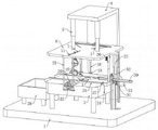
Fig. 1 is a schematic view of the overall structure of the present invention.
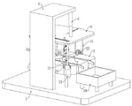
Fig. 2 is a rear view of the overall structure of the present invention.
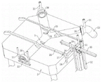
Fig. 3 is a schematic top view structure of the carrier stage of the present invention.
FIG. 4 is a schematic top view of the mounting plate of the present invention.
FIG. 5 is a bottom view of the mounting plate of the present invention.
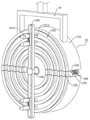
Fig. 6 is a schematic view of the grinding mechanism of the present invention.
Fig. 7 is a schematic view of the mounting structure of the U-shaped frame of the present invention.
FIG. 8 is a schematic structural view of a sliding connection portion between the T-shaped mounting block and the mounting frame of the present invention.
In the figure: 1. a base; 2. a bearing table; 3. a Y-shaped placing groove; 4. an L-shaped frame; 5. an electric telescopic rod; 6. mounting a plate; 7. a chute; 8. a slider; 9. a connecting frame; 10. a polishing mechanism; 101. a carrier tray; 102. an arc-shaped guide track; 103. a through groove; 104. a slider; 105. clamping a rail; 106. a pressure spring; 107. a drive motor; 108. a rotating shaft; 109. installing a frame; 1010. a tension spring; 1011. a T-shaped mounting block; 1012. a roller; 1013. a slide base; 1014. a sliding mounting block; 1015. grinding a roller; 11. a first threaded rod; 12. a first bump; 13. a traveler; 14. a sliding frame; 15. a second threaded rod; 16. a second bump; 17. a U-shaped frame; 18. a spring telescopic compression bar; 19. an arc-shaped pressing plate; 20. an arc-shaped baffle plate; 21. a first spring telescopic rod; 22. a blower; 23. a collection pipe; 24. a strip-shaped groove; 25. a top plate; 26. a second spring telescopic rod; 27. a U-shaped limiting plate; 28. a collection box; 29. a square ring; 30. a first rack; 31. a gear; 32. a second rack; 33. an arc-shaped plate.
Detailed Description
The technical solutions in the embodiments of the present invention will be clearly and completely described below with reference to the drawings in the embodiments of the present invention, and it is obvious that the described embodiments are only a part of the embodiments of the present invention, and not all of the embodiments. All other embodiments, which can be derived by a person skilled in the art from the embodiments given herein without making any creative effort, shall fall within the protection scope of the present invention.
Referring to fig. 1, fig. 3, fig. 4 and fig. 5, the present invention provides a technical solution: a Y-shaped three-way cast pipe polishing device comprises a base 1, wherein the upper end face of the base 1 is fixedly connected with a bearing platform 2 through a fixed column, the upper end face of the bearing platform 2 is provided with a Y-shaped placing groove 3 for placing a three-way pipe, the upper end face of the base 1 is fixedly connected with an L-shaped frame 4 behind the bearing platform 2, the lower end face of the transverse section of the L-shaped frame 4 is fixedly connected with a mounting plate 6 through an electric telescopic rod 5, the upper end face of the mounting plate 6 is provided with three sliding grooves 7 corresponding to the Y-shaped placing groove 3, sliding blocks 8 are respectively and slidably connected inside the sliding grooves 7, the lower end face of each sliding block 8 is fixedly connected with a polishing mechanism 10 through a connecting frame 9, the front end face of each sliding block 8 positioned in the front part of the mounting plate 6 is rotatably connected with a first threaded rod 11, the front part of the upper end face of the mounting plate 6 is fixedly connected with a first lug 12, the first lug 12 is in threaded connection on each first threaded rod 11, and sliding columns 13 are respectively and fixedly connected on the upper end faces of two sliding blocks 8 transversely adjacent to the rear part of the mounting plate 6, and two travelers 13 outside common sliding connection have a sliding frame 14, sliding frame 14 rear end face rotates and is connected with second threaded rod 15, mounting panel 6 up end rear portion fixedly connected with second lug 16, threaded connection has second lug 16 on the second threaded rod 15, terminal surface passes through spring telescopic compression bar 18 fixedly connected with a plurality of and Y shape standing groove 3 matched with arc clamp plate 19 under the mounting panel 6, and arc clamp plate 19 is the distribution of triangle-shaped shape, the cell wall just is located the below of arc clamp plate 19 through spring telescopic ejector pin fixedly connected with arc 33 in the Y shape standing groove 3.
Referring to fig. 6, 7 and 8, the polishing mechanism 10 includes a bearing disc 101, the bearing disc 101 is fixedly connected to the lower portion of the connecting frame 9, a plurality of arc-shaped guide rails 102 are fixedly connected to one side end surface of the bearing disc 101 from outside to inside in sequence, the cross section of each arc-shaped guide rail 102 is T-shaped, two through grooves 103 are symmetrically formed in the horizontal direction of the side end surface of the bearing disc 101, sliding blocks 104 are slidably connected to the inside of the through grooves 103, a plurality of connecting clamping rails 105 matched with the arc-shaped guide rails 102 are fixedly connected to one side end surface of each sliding block 104 close to the corresponding arc-shaped guide rail 102 from outside to inside, the connecting clamping rails 105 and the arc-shaped guide rails 102 are completely circular when being closed together, a connecting plate is fixedly connected between the upper groove wall and the lower groove wall of each through the through grooves 103, a pressure spring 106 is fixedly connected between the sliding blocks 104 and the connecting plate, a driving motor 107 is fixedly connected to one side end surface of the bearing disc 101 far from the corresponding arc-shaped guide rail 102 through a fixing frame, the driving motor 107 is fixedly connected with a rotating shaft 108 through an output shaft, the rotating shaft 108 penetrates through the circular center of the side end face of the bearing disc 101, the two sliding blocks 104 are mutually and fixedly connected through a U-shaped frame 17, and the U-shaped frame 17 is sleeved outside the rotating shaft 108.
Referring to fig. 8, two mounting frames 109 are symmetrically and fixedly connected to an end of the rotating shaft 108 close to the arc-shaped guide rail 102 from top to bottom, a T-shaped mounting block 1011 is slidably connected to an inside of each mounting frame 109, two rollers 1012 are symmetrically and rotatably connected to an end surface of the T-shaped mounting block 1011 close to the arc-shaped guide rail 102, the rollers 1012 respectively abut against an outer wall and an inner wall of the arc-shaped guide rail 102, a sliding seat 1013 is fixedly connected to an end surface of the T-shaped mounting block 1011 far away from the arc-shaped guide rail 102, a sliding mounting block 1014 is slidably connected to an inside of the sliding seat 1013, a polishing roller 1015 is rotatably connected to an end surface of the sliding mounting block 1014 far away from the sliding seat 1013, and a tension spring 1010 is fixedly connected between an end surface of the sliding mounting block 1014 and an inner wall of the sliding groove 7.
Before polishing, firstly, a Y-shaped three-way cast pipe is placed on an arc-shaped plate 33 in a Y-shaped placing groove 3, then a first threaded rod 11 and a second threaded rod 15 are rotated according to the length of the three-way cast pipe to adjust the position of a polishing mechanism 10, the first threaded rod 11 is rotated to drive a slide block 8 connected with the first threaded rod to move forwards or backwards, so that the polishing mechanism 10 positioned in the front part of a mounting plate 6 and the front port of the three-way cast pipe are positioned on the same plane, the second threaded rod 15 is rotated to drive a sliding frame 14 to move forwards or backwards, the sliding frame 14 drives the slide blocks 8 positioned in two sliding grooves 7 at the rear part of the mounting plate 6 to move through a sliding column 13, the slide block 8 positioned at the rear part of the mounting plate 6 moves and drives the polishing mechanism 10 positioned below the sliding block to move, so that the polishing mechanism 10 at the rear part and the two ports at the rear part of the three-way cast pipe are positioned on the same plane, and then a U-shaped frame 17 is pulled according to the diameter size of the pipe orifice of the three-way cast pipe to drive the sliding block 104 to move, so that the connecting clamping rail 105 on the sliding block 104 is separated from the arc-shaped guide rail 102, then the rotating shaft 108 is rotated to drive the mounting frame 109 to rotate, the position of the mounting frame 109 is flush with the position of the through groove 103 and is on the same horizontal line, then the sliding mounting block 1014 slides and selects the arc-shaped guide rail 102 at a proper position according to the size of the pipe orifice of the three-way cast pipe, and the mounting frame 109 is rotated to enable the roller 1012 to slide into the selected arc-shaped guide rail 102, the U-shaped frame 17 is loosened, the pressure spring 106 is reset, extended and the sliding block 104 is pushed to move, so that the connecting clamping rail 105 and the arc-shaped guide rail 102 are mutually aligned together.
Then the electric telescopic rod 5 is started to drive the mounting plate 6 to descend, the arc-shaped pressing plate 19 is abutted against the upper part of the three-way cast pipe in the descending process of the mounting plate 6, the spring telescopic pressing rod 18 is compressed to clamp and fix the three-way cast pipe, the electric telescopic rod 5 drives the mounting plate 6 to descend continuously until the bearing plate 101 and the pipe orifice of the three-way cast pipe are positioned on the same axis, the mounting plate 6 stops descending, then the first threaded rod 11 and the second threaded rod 15 are rotated again to drive the polishing mechanism 10 to move close to the port position of the three-way cast pipe, so that the polishing rollers 1015 are sleeved on the outer wall and the inner wall of the pipe orifice, as one end of the polishing roller 1015 is in a conical shape, the polishing roller 1015 slides to the outer wall and the inner wall of the pipe orifice conveniently, finally the driving motor 107 is started to drive the rotating shaft 108 to rotate, the rotating shaft 108 then drives the mounting frame 109 to rotate, so that the polishing roller 1015 rotates at the pipe orifice of the three-way cast pipe to polish the pipe orifice, can polish the processing to three mouths of pipe of tee bend cast tube simultaneously, and can also adjust according to orificial size, be applicable to the tee bend cast tube of different pipe diameter sizes.
Referring to fig. 1, 2 and 3, in this embodiment, arc-shaped baffles 20 are fixedly connected to the front end surface and the rear end surface of the plummer 2 and located at the notches of the Y-shaped placing grooves 3, a transverse plate is fixedly connected to the front portion of the lower end surface of the mounting plate 6 and located above the front notches of the Y-shaped placing grooves 3 through a first spring expansion rod 21, a blower 22 is fixedly connected to the upper end surface of the transverse plate, and a collecting pipe 23 is also fixedly connected to the rear portion of the lower end surface of the mounting plate 6 and located above the two rear notches of the Y-shaped placing grooves 3 through the first spring expansion rod 21.
After polishing, the electric telescopic rod 5 drives the mounting plate 6 to ascend, and drives the blower 22 and the collecting pipe 23 to ascend through the first spring telescopic rod 21, then the blower 22 and the collecting pipe 23 are supported by the arc baffle plate 20, at the same time, the blower 22 and the collecting pipe 23 are on the same axis with the port of the three-way cast pipe, then the blower 22 is started, the blower 22 blows in air flow from the pipe orifice in the front part of the three-way cast pipe, the air flow enters the inside of the three-way cast pipe to drive the chips polished inside to be discharged from the two pipe orifices in the rear part, and finally the chips enter the collecting pipe 23 to complete the collection of the chips.
Referring to fig. 1, 2 and 3, in this embodiment, two strip-shaped grooves 24 are symmetrically formed in front and back of the upper end surface of the carrier 2, top plates 25 are slidably connected to the strip-shaped grooves 24, support plates are fixedly connected to the right end surfaces of the two top plates 25, a second spring telescopic rod 26 is fixedly connected between the upper end surface of each support plate and the lower end surface of the mounting plate 6, U-shaped limit plates 27 are fixedly connected to the right portion of the upper end surface of the carrier 2 and above the two strip-shaped grooves 24, arc-shaped grooves are formed in the upper end surface of each top plate 25, which can limit three-way cast tubes and prevent the three-way cast tubes from sliding randomly, the left portion of each top plate 25 is in an inclined shape with a lower left portion and a higher portion, so that the three-way cast tubes can slide into the collecting box 28 under the action of gravity, a vertical rod collecting box 28 is fixedly connected to the left portion of the upper end surface of the base 1 and below the left portion of the top plate 25, and a square ring 29 is fixedly connected to the upper end surface of the base 1, the inside sliding connection of quad ring 29 has first rack 30, and first rack 30 left end face fixedly connected with ejector pad, and the riser fixedly connected with rotary column is passed through to base 1 up end right part, and the rotary column outside is rotated and is connected with the gear 31 with first rack 30 engaged with, and the mounting panel 6 lower extreme face right part is through second rack 32 that mounting bar fixedly connected with and gear 31 engaged with.
When the mounting plate 6 is pushed to the lowest part by the electric telescopic rod 5, the second spring telescopic rod 26 is in a compressed state, the top plate 25 is located at the bottom of the strip-shaped groove 24, the electric telescopic rod 5 drives the mounting plate 6 to ascend, the arc-shaped pressing plate 19 is separated from the upper part of the three-way casting pipe, the elastic section of the second spring telescopic rod 26 extends to the longest distance and drives the support plate to ascend, the support plate drives the top plate 25 to ascend, the top plate 25 drives the Y-shaped three-way casting pipe to ascend until the Y-shaped three-way casting pipe ascends from the Y-shaped placing groove 3, the top plate 25 abuts against the U-shaped limiting plate 27 to stop ascending, the mounting plate 6 continues to move upwards to drive the second spring telescopic rod 26 to extend, the second spring telescopic rod 26 is stretched, the mounting plate 6 drives the second rack 32 to ascend, the second rack 32 is meshed with the gear 31 to be connected together and drives the gear 31 to rotate, and the gear 31 drives the first rack 30 to move leftwards, the first rack 30 pushes the three-way cast pipe to move leftwards through the push block until the three-way cast pipe slides into the collecting box 28, so that the three-way cast pipe after being polished can be automatically taken out.
When the three-way casting pipe polishing machine works, a three-way casting pipe to be polished is placed into a Y-shaped placing groove 3, then an electric telescopic rod 5 is started to drive a mounting plate 6 to descend, an arc-shaped pressing plate 19 is extruded by a spring telescopic pressing rod 18 to abut against the upper portion of the three-way casting pipe, the mounting plate 6 continues to descend until a polishing mechanism 10 and the pipe orifice of the three-way casting pipe are positioned on the same axis, then the position of a sliding mounting block 1014 is adjusted according to the size of the pipe orifice, then the position of a polishing roller 1015 is adjusted through a first threaded rod 11 and a second threaded rod 15, so that the polishing roller 1015 abuts against the surface wall of the pipe orifice, then a driving motor 107 is started to drive the polishing roller 1015 to rotate, so that the pipe orifice can be polished, after polishing is completed, the electric telescopic rod 5 is controlled to drive the mounting plate 6 to ascend, at the moment, the first spring telescopic rod 21 is stretched, a blower 22 and a collecting pipe 23 are abutted by the arc-shaped baffle plate 20 and are positioned on the same axis with the pipe orifice of the three-way casting pipe, the blower 22 and the collecting pipe 23 cooperate with each other to remove and collect the debris, the mounting plate 6 continues to ascend to drive the arc-shaped pressing plate 19 to be separated from the upper part of the three-way cast pipe, the second spring telescopic rod 26 is stretched and drives the top plate 25 to ascend, the top plate 25 ejects the three-way cast pipe out of the Y-shaped placing groove 3, and finally the three-way cast pipe is ejected to slide into the collecting box 28 through the cooperation of the first rack 30, the second rack 32 and the gear 31.
It is noted that, herein, relational terms such as first and second, and the like may be used solely to distinguish one entity or action from another entity or action without necessarily requiring or implying any actual such relationship or order between such entities or actions. Also, the terms "comprises," "comprising," or any other variation thereof, are intended to cover a non-exclusive inclusion, such that a process, method, article, or apparatus that comprises a list of elements does not include only those elements but may include other elements not expressly listed or inherent to such process, method, article, or apparatus. Without further limitation. The use of the phrase "comprising one of the elements does not exclude the presence of other like elements in the process, method, article, or apparatus that comprises the element.
Although embodiments of the present invention have been shown and described, it will be appreciated by those skilled in the art that changes, modifications, substitutions and alterations can be made in these embodiments without departing from the principles and spirit of the invention, the scope of which is defined in the appended claims and their equivalents.
Claims (9)
1. The utility model provides a Y type tee bend cast tube grinding device, includes base (1), its characterized in that: the upper end face of the base (1) is fixedly connected with a bearing table (2) through a fixing column, a Y-shaped placing groove (3) for placing a three-way pipe is formed in the upper end face of the bearing table (2), the upper end face of the base (1) is located behind the bearing table (2) and is fixedly connected with an L-shaped frame (4), the lower end face of the transverse section of the L-shaped frame (4) is fixedly connected with a mounting plate (6) through an electric telescopic rod (5), three sliding grooves (7) corresponding to the Y-shaped placing groove (3) are formed in the upper end face of the mounting plate (6), sliding blocks (8) are connected inside the sliding grooves (7) in a sliding mode, and the lower end face of each sliding block (8) is fixedly connected with a polishing mechanism (10) through a connecting frame (9);
the polishing mechanism (10) comprises a bearing disc (101), the bearing disc (101) is fixedly connected to the lower portion of a connecting frame (9), a plurality of arc-shaped guide rails (102) are fixedly connected to one side end face of the bearing disc (101) from outside to inside in sequence, the cross section of each arc-shaped guide rail (102) is T-shaped, two through grooves (103) are symmetrically formed in the horizontal direction of the side end face of the bearing disc (101), sliding blocks (104) are slidably connected inside the through grooves (103), a plurality of connecting clamping rails (105) matched with the arc-shaped guide rails (102) are fixedly connected to one side end face, close to the arc-shaped guide rails (102), of each sliding block (104) from outside to inside, the connecting clamping rails (105) and the arc-shaped guide rails (102) are complete circles when the connecting clamping rails (105) and the arc-shaped guide rails (102) are combined together, and a connecting plate is fixedly connected between the upper groove wall and the lower groove wall of each through groove (103), the sliding block (104) and the connecting plate are fixedly connected with a pressure spring (106) together, one side end face of the bearing disc (101) far away from the arc-shaped guide track (102) is fixedly connected with a driving motor (107) through a fixing frame, the driving motor (107) is fixedly connected with a rotating shaft (108) through an output shaft, the rotating shaft (108) penetrates through the round center part of the side end face of the bearing disc (101), one end of the rotating shaft (108) close to the arc-shaped guide track (102) is symmetrically and fixedly connected with two installation frames (109) up and down, a T-shaped installation block (1011) is slidably connected inside the installation frame (109), one side end face of the T-shaped installation block (1011) close to the arc-shaped guide track (102) is symmetrically and rotatably connected with two rollers (1012), the rollers (1012) are respectively abutted against the outer wall and the inner wall of the arc-shaped guide track (102), one side end face of the T-shaped installation block (1011) far away from the arc-shaped guide track (102) is fixedly connected with a sliding seat (1013), the grinding device is characterized in that a sliding installation block (1014) is connected to the inner portion of the sliding seat (1013) in a sliding mode, a grinding roller (1015) is connected to the end face, far away from the sliding seat (1013), of one side of the sliding installation block (1014) in a rotating mode, and a tension spring (1010) is fixedly connected between the end face of the side of the sliding installation block (1014) and the inner groove wall of the sliding groove (7) in a common mode.
2. The Y-shaped three-way cast pipe grinding device according to claim 1, characterized in that: be located mounting panel (6) anterior terminal surface rotates before slider (8) and is connected with first threaded rod (11), the first lug of the front fixedly connected with of mounting panel (6) up end (12), threaded connection has first lug (12) on first threaded rod (11), is located the equal fixedly connected with traveller (13) of two horizontal adjacent slider (8) up end in mounting panel (6) rear portion, and two travelers (13) outside common sliding connection have sliding frame (14), sliding frame (14) rear end face rotates and is connected with second threaded rod (15), mounting panel (6) up end rear portion fixedly connected with second lug (16), threaded connection has second lug (16) on second threaded rod (15).
3. The Y-shaped three-way cast pipe grinding device according to claim 1, characterized in that: the two sliding blocks (104) are fixedly connected with each other through the U-shaped frame (17), and the U-shaped frame (17) is sleeved outside the rotating shaft (108).
4. The Y-shaped three-way cast pipe grinding device according to claim 1, characterized in that: terminal surface passes through spring telescopic pressing rod (18) fixedly connected with a plurality of and Y shape standing groove (3) matched with arc clamp plate (19) under mounting panel (6), and arc clamp plate (19) distribute for triangle-shaped, cell wall just is located the below of arc clamp plate (19) through spring telescopic ejector pin fixedly connected with arc (33) in Y shape standing groove (3).
5. The Y-shaped three-way cast pipe grinding device according to claim 1, characterized in that: terminal surface and rear end face just are located equal fixedly connected with cowl (20) of notch department of Y shape standing groove (3) before plummer (2), terminal surface front portion just is located the front portion notch top of Y shape standing groove (3) through first spring telescopic link (21) fixedly connected with diaphragm under mounting panel (6), diaphragm up end fixedly connected with hair-dryer (22), terminal surface rear portion also is located two rear portion notch tops of Y shape standing groove (3) also through first spring telescopic link (21) fixedly connected with collecting pipe (23) under mounting panel (6).
6. The Y-shaped three-way cast pipe grinding device according to claim 1, characterized in that: two bar grooves (24) have been seted up to the symmetry before plummer (2) up end, the inside equal sliding connection in bar groove (24) has roof (25), two the common fixedly connected with extension board of roof (25) right-hand member face, common fixedly connected with second spring telescopic link (26) between extension board up end and mounting panel (6) lower terminal surface, plummer (2) up end right part just is located the equal fixedly connected with U-shaped limiting plate (27) in top in two bar grooves (24).
7. The Y-shaped three-way cast pipe grinding device according to claim 6, wherein: the arc-shaped groove is formed in the upper end face of the top plate (25), and the left portion of the top plate (25) is in an inclined shape with a lower left portion and a higher right portion.
8. The Y-shaped three-way cast pipe grinding device according to claim 6, wherein: the base (1) up end left part just is located roof (25) left part below and passes through montant fixedly connected with collecting box (28).
9. The Y-shaped three-way cast pipe grinding device according to claim 1, characterized in that: base (1) up end passes through branch fixedly connected with quad ring (29), quad ring (29) inside sliding connection has first rack (30), first rack (30) left end face fixedly connected with ejector pad, riser fixedly connected with rotary column is passed through to base (1) up end right part, the rotary column outside is rotated and is connected with gear (31) with first rack (30) mesh mutually, mounting panel (6) lower extreme face right part is through second rack (32) of installation pole fixedly connected with and gear (31) mesh mutually.
Priority Applications (1)
| Application Number | Priority Date | Filing Date | Title |
|---|---|---|---|
| CN202210221278.6A CN114310518B (en) | 2022-03-09 | 2022-03-09 | Y-shaped tee cast pipe polishing device |
Applications Claiming Priority (1)
| Application Number | Priority Date | Filing Date | Title |
|---|---|---|---|
| CN202210221278.6A CN114310518B (en) | 2022-03-09 | 2022-03-09 | Y-shaped tee cast pipe polishing device |
Publications (2)
| Publication Number | Publication Date |
|---|---|
| CN114310518A CN114310518A (en) | 2022-04-12 |
| CN114310518B true CN114310518B (en) | 2022-05-24 |
Family
ID=81033211
Family Applications (1)
| Application Number | Title | Priority Date | Filing Date |
|---|---|---|---|
| CN202210221278.6A Active CN114310518B (en) | 2022-03-09 | 2022-03-09 | Y-shaped tee cast pipe polishing device |
Country Status (1)
| Country | Link |
|---|---|
| CN (1) | CN114310518B (en) |
Families Citing this family (6)
| Publication number | Priority date | Publication date | Assignee | Title |
|---|---|---|---|---|
| CN114571311A (en) * | 2022-05-09 | 2022-06-03 | 徐州好合智能装备有限公司 | Stainless steel cross pipe joint surface burr remove device |
| CN115041879B (en) * | 2022-07-27 | 2024-01-05 | 哈尔滨工业大学(深圳) | Assembled concrete structure connected node welding equipment |
| CN115319555B (en) * | 2022-09-15 | 2024-08-09 | 晋城市佳翔铸业有限公司 | Y-shaped tee casting pipe polishing device |
| CN115431128B (en) * | 2022-09-21 | 2023-09-08 | 徐州市瑞泰钢管有限公司 | Precision polishing treatment machine before welding groove of metal pipe fitting |
| CN116038208B (en) * | 2022-12-07 | 2023-11-14 | 中国建筑第五工程局有限公司 | Steel construction connected node welding set |
| CN117300778B (en) * | 2023-10-19 | 2024-03-12 | 河北世纪新星管业有限公司 | Y-shaped tee pipe fitting inner wall polishing device |
Family Cites Families (9)
| Publication number | Priority date | Publication date | Assignee | Title |
|---|---|---|---|---|
| US6220939B1 (en) * | 1998-06-02 | 2001-04-24 | James E. Pruitt | Method and apparatus for grinding round parts |
| CN106863059B (en) * | 2017-04-19 | 2018-12-28 | 荆门创佳机械科技有限公司 | A kind of device of the inside and outside burr of nozzle for the steel pipe that can polish simultaneously |
| CN108481137A (en) * | 2018-06-06 | 2018-09-04 | 芜湖市奥尔特光电科技有限公司 | It is a kind of to be convenient for tubular fitting grinding device fixed and that grinding efficiency can be improved |
| CN108788993A (en) * | 2018-07-13 | 2018-11-13 | 成都蒲江珂贤科技有限公司 | A kind of tubing vertical section grinding device |
| CN109605147A (en) * | 2019-01-25 | 2019-04-12 | 沈勤娟 | Grinding device is used in a kind of processing of stainless steel pipe |
| CN212240360U (en) * | 2020-04-08 | 2020-12-29 | 潍坊贵昌机械有限公司 | Deburring device of abnormal shape three-way pipe |
| CN112171400B (en) * | 2020-09-15 | 2022-11-25 | 山东恒智一建净化工程有限公司 | Building pipe inner wall processing system |
| CN113043089A (en) * | 2021-02-23 | 2021-06-29 | 章余 | Scouting robot battery protective housing grinding device |
| CN113500409B (en) * | 2021-09-08 | 2021-11-19 | 南通市力行机械制造有限公司 | Drilling device for end face of barbell disc |
-
2022
- 2022-03-09 CN CN202210221278.6A patent/CN114310518B/en active Active
Also Published As
| Publication number | Publication date |
|---|---|
| CN114310518A (en) | 2022-04-12 |
Similar Documents
| Publication | Publication Date | Title |
|---|---|---|
| CN114310518B (en) | Y-shaped tee cast pipe polishing device | |
| CN110556982B (en) | Stator and rotor punching sheet processing production line | |
| CN114161277A (en) | Pipe fitting welding seam equipment of polishing | |
| CN115056048A (en) | Transmission shaft machining device with eccentric detection function | |
| CN112643489B (en) | Sanding equipment for furniture board processing | |
| CN116175299A (en) | Dust removal grinding device is used in quartz tube processing | |
| CN115228927A (en) | Stainless steel finishing mill group | |
| CN208084113U (en) | Polissoir in a kind of stainless steel tube | |
| CN114770242A (en) | Special-shaped bearing production equipment with abrasive machining function | |
| CN110367876A (en) | A kind of keyboard dust collector | |
| CN109794829A (en) | Polishing device for steel box girder T rib sliced mouth | |
| CN112454061B (en) | Stainless steel section bar grinding device with dust removal function | |
| CN117506680A (en) | Polishing equipment for intelligent furniture maintenance | |
| CN211249574U (en) | Polishing machine for plastic support production | |
| CN112658904A (en) | Grinding device is used in mould production | |
| CN112295325A (en) | Dust purification treatment device for stone carving | |
| CN114950790B (en) | Paint spraying device for brake hub | |
| CN216398412U (en) | Dust removal device of laser engraving machine | |
| CN114505746B (en) | Burr removing device and method capable of moving in multiple routes for machining | |
| CN217491970U (en) | Tire inner side tire hair suction device | |
| CN215357683U (en) | Edging dust collector for wood working | |
| CN113770855B (en) | Plywood surface polishing and deburring equipment | |
| CN215394352U (en) | Grinding machine for transformer processing | |
| CN211890458U (en) | Sand blasting machine capable of achieving multi-layer screening | |
| CN113400135A (en) | Edging dust collector for wood working |
Legal Events
| Date | Code | Title | Description |
|---|---|---|---|
| PB01 | Publication | ||
| PB01 | Publication | ||
| SE01 | Entry into force of request for substantive examination | ||
| SE01 | Entry into force of request for substantive examination | ||
| GR01 | Patent grant | ||
| GR01 | Patent grant |