CN1142407A - Filtering flow in valve - Google Patents
Filtering flow in valve Download PDFInfo
- Publication number
- CN1142407A CN1142407A CN96105065A CN96105065A CN1142407A CN 1142407 A CN1142407 A CN 1142407A CN 96105065 A CN96105065 A CN 96105065A CN 96105065 A CN96105065 A CN 96105065A CN 1142407 A CN1142407 A CN 1142407A
- Authority
- CN
- China
- Prior art keywords
- mentioned
- cup
- valve
- graticule mesh
- shaped
- Prior art date
- Legal status (The legal status is an assumption and is not a legal conclusion. Google has not performed a legal analysis and makes no representation as to the accuracy of the status listed.)
- Pending
Links
- 238000001914 filtration Methods 0.000 title claims abstract description 18
- 239000012530 fluid Substances 0.000 claims description 13
- 239000002245 particle Substances 0.000 claims description 11
- 238000000034 method Methods 0.000 claims description 5
- 239000002991 molded plastic Substances 0.000 claims description 2
- 230000000903 blocking effect Effects 0.000 claims 1
- 238000009434 installation Methods 0.000 claims 1
- 238000000465 moulding Methods 0.000 claims 1
- 238000011144 upstream manufacturing Methods 0.000 claims 1
- XLYOFNOQVPJJNP-UHFFFAOYSA-N water Substances O XLYOFNOQVPJJNP-UHFFFAOYSA-N 0.000 description 8
- 238000007789 sealing Methods 0.000 description 4
- 239000012535 impurity Substances 0.000 description 3
- 230000000694 effects Effects 0.000 description 2
- 230000014509 gene expression Effects 0.000 description 2
- 230000004323 axial length Effects 0.000 description 1
- 230000015556 catabolic process Effects 0.000 description 1
- 230000006378 damage Effects 0.000 description 1
- 238000004851 dishwashing Methods 0.000 description 1
- 239000004744 fabric Substances 0.000 description 1
- 239000011810 insulating material Substances 0.000 description 1
- 238000012986 modification Methods 0.000 description 1
- 230000004048 modification Effects 0.000 description 1
- 239000004033 plastic Substances 0.000 description 1
- 229920003023 plastic Polymers 0.000 description 1
- 230000002787 reinforcement Effects 0.000 description 1
- 238000005406 washing Methods 0.000 description 1
Images


Classifications
-
- B—PERFORMING OPERATIONS; TRANSPORTING
- B01—PHYSICAL OR CHEMICAL PROCESSES OR APPARATUS IN GENERAL
- B01D—SEPARATION
- B01D35/00—Filtering devices having features not specifically covered by groups B01D24/00 - B01D33/00, or for applications not specifically covered by groups B01D24/00 - B01D33/00; Auxiliary devices for filtration; Filter housing constructions
- B01D35/02—Filters adapted for location in special places, e.g. pipe-lines, pumps, stop-cocks
- B01D35/04—Plug, tap, or cock filters filtering elements mounted in or on a faucet
-
- B—PERFORMING OPERATIONS; TRANSPORTING
- B01—PHYSICAL OR CHEMICAL PROCESSES OR APPARATUS IN GENERAL
- B01D—SEPARATION
- B01D35/00—Filtering devices having features not specifically covered by groups B01D24/00 - B01D33/00, or for applications not specifically covered by groups B01D24/00 - B01D33/00; Auxiliary devices for filtration; Filter housing constructions
- B01D35/30—Filter housing constructions
-
- F—MECHANICAL ENGINEERING; LIGHTING; HEATING; WEAPONS; BLASTING
- F16—ENGINEERING ELEMENTS AND UNITS; GENERAL MEASURES FOR PRODUCING AND MAINTAINING EFFECTIVE FUNCTIONING OF MACHINES OR INSTALLATIONS; THERMAL INSULATION IN GENERAL
- F16K—VALVES; TAPS; COCKS; ACTUATING-FLOATS; DEVICES FOR VENTING OR AERATING
- F16K31/00—Actuating devices; Operating means; Releasing devices
- F16K31/12—Actuating devices; Operating means; Releasing devices actuated by fluid
- F16K31/36—Actuating devices; Operating means; Releasing devices actuated by fluid in which fluid from the circuit is constantly supplied to the fluid motor
- F16K31/40—Actuating devices; Operating means; Releasing devices actuated by fluid in which fluid from the circuit is constantly supplied to the fluid motor with electrically-actuated member in the discharge of the motor
- F16K31/402—Actuating devices; Operating means; Releasing devices actuated by fluid in which fluid from the circuit is constantly supplied to the fluid motor with electrically-actuated member in the discharge of the motor acting on a diaphragm
- F16K31/404—Actuating devices; Operating means; Releasing devices actuated by fluid in which fluid from the circuit is constantly supplied to the fluid motor with electrically-actuated member in the discharge of the motor acting on a diaphragm the discharge being effected through the diaphragm and being blockable by an electrically-actuated member making contact with the diaphragm
-
- Y—GENERAL TAGGING OF NEW TECHNOLOGICAL DEVELOPMENTS; GENERAL TAGGING OF CROSS-SECTIONAL TECHNOLOGIES SPANNING OVER SEVERAL SECTIONS OF THE IPC; TECHNICAL SUBJECTS COVERED BY FORMER USPC CROSS-REFERENCE ART COLLECTIONS [XRACs] AND DIGESTS
- Y10—TECHNICAL SUBJECTS COVERED BY FORMER USPC
- Y10T—TECHNICAL SUBJECTS COVERED BY FORMER US CLASSIFICATION
- Y10T137/00—Fluid handling
- Y10T137/794—With means for separating solid material from the fluid
- Y10T137/7976—Plural separating elements
-
- Y—GENERAL TAGGING OF NEW TECHNOLOGICAL DEVELOPMENTS; GENERAL TAGGING OF CROSS-SECTIONAL TECHNOLOGIES SPANNING OVER SEVERAL SECTIONS OF THE IPC; TECHNICAL SUBJECTS COVERED BY FORMER USPC CROSS-REFERENCE ART COLLECTIONS [XRACs] AND DIGESTS
- Y10—TECHNICAL SUBJECTS COVERED BY FORMER USPC
- Y10T—TECHNICAL SUBJECTS COVERED BY FORMER US CLASSIFICATION
- Y10T137/00—Fluid handling
- Y10T137/794—With means for separating solid material from the fluid
- Y10T137/8013—Sediment chamber
-
- Y—GENERAL TAGGING OF NEW TECHNOLOGICAL DEVELOPMENTS; GENERAL TAGGING OF CROSS-SECTIONAL TECHNOLOGIES SPANNING OVER SEVERAL SECTIONS OF THE IPC; TECHNICAL SUBJECTS COVERED BY FORMER USPC CROSS-REFERENCE ART COLLECTIONS [XRACs] AND DIGESTS
- Y10—TECHNICAL SUBJECTS COVERED BY FORMER USPC
- Y10T—TECHNICAL SUBJECTS COVERED BY FORMER US CLASSIFICATION
- Y10T137/00—Fluid handling
- Y10T137/794—With means for separating solid material from the fluid
- Y10T137/8085—Hollow strainer, fluid inlet and outlet perpendicular to each other
Abstract
A unitary cup-shaped grid member having a grid of holes in the closed end is inserted in the inlet of a valve and a cup-shaped fine-mesh primary filter screen inserted therein and snap-locked in place. In the event the screen clogs and is removed by the user, the grid provides some back-up or auxiliary course filtering to protect the valve in service after removal of the primary filter screen.
Description
The present invention relates to filter or hold back the particle in the fluid that flows through valve, particularly flow through the particle in the water of electronic control type valve, this electronic control type valve applications with equipment that municipal water sources or family expenses water source are connected in.This valve is commonly used to the current in control example such as these equipment of dish-washing machine, washing machine and refrigerating ice making machine.The feed water valve of this equipment is usually by the operation of the solenoid controller of low current, and sort controller only has several ounces or a few gram force to be used for breakdown or shut off valve parts.This valve thereby very sensitive to the effect that is trapped in the impurity particle between valve seat or the moving component gradually in the water source, this causes valve closing to lose efficacy or seepage.
In the past, used at the valve inlet place to have and be used to hold back the fine mesh of small particle or the screen pack of aperture prevents that this particle is blocked between movable valve member and the valve seat gradually.But the granular deposit that the fine mesh of this braid fabric in use tends to be held back from the water source gradually stops up, and causes flowing to the flow minimizing of valve or being plugged.For remedying this situation, the user needs valve is unloaded down from the water source, firmly removes filter screen, so that the fluid flow valve.Once remove filter screen from valve, valve just can not prevent the destruction of impurity particle thing, and experience shows, because particle is blocked between the valve member of valve seat, can cause the seepage of valve very soon.
Therefore expectation always provides a kind of cost-effective method for a long time, after the user has a mind to shed original filter screen, still can carry out the dregs filtration or stop that particle leads to feed water valve.
An object of the present invention is to provide a kind of filtration graticule mesh auxiliary or reserve, so that after the user sheds original filter screen, protect the valve operation.
Another object of the present invention provides a kind of filtration graticule mesh that is used for the current valve auxiliary or reserve, this valve has cup-shaped graticule mesh, this lattice net-shape cup-shaped, but quick-action ground kayser in valve inlet, filter screen then quick-action ground kayser on cup-shaped graticule mesh parts.
Graticule mesh auxiliary or reserve of the present invention comprises integrally formed cup-shaped graticule mesh part, and this graticule mesh part has many filtering holes spaced apart that form at cup-shaped closed end.The graticule mesh parts be force-fitted in or fast kayser in the inlet of valve.In preferred enforcement, cup shell has conical sidewall, forms inside groove on this sidewall, is used for holding in the mode of interference fit or kayser engagement fast the flange of original cup-shaped wire gauze filter.
Fig. 1 is an axonometric drawing of using electric control valve assembly of the present invention;
Fig. 2 is the part along the cutaway view shown in the 2-2 among Fig. 1;
Fig. 3 is the part isometrical drawing of integral filter graticule mesh of the present invention;
Fig. 4 is along the cutaway view shown in the 4-4 line among Fig. 1.
With reference to Fig. 1 and 4, the electric control valve assembly that total usefulness 10 is represented comprises the valve body 12 with inlet connector 14, outlet connector 16 and solenoid controller 18, solenoid controller has field frame 20, and power connection end 22,24 is arranged on this framework, so that solenoid is connected with power supply.Solenoid 18 comprises the coil 26 of conductive wire, and this coil is encapsulated in by the insulating materials of numbering 28 expressions for example in the plastics, and have arrangement in coil the axially spaced-apart certain distance and form the tubular pole piece 30,32 of air-gap betwixt.Tubular pole piece 30,32 extends between the two ends of roughly c-shaped field frame 20 relative to one another.
Armature guide pipe 34 has the closed end that upwards stretches into pivoting pole piece 30,32, and this guide pipe 34 is slidingly matched with armature assembly 38, and this armature assembly is subjected to the bias voltage of spring 40 downward directions.The upper end of spring 40 is positioned on the lower surface of guide pipe 34 closed ends, and guide rod is then made with the upper end of armature in its bottom.Field frame 20 can adopt any suitable fastening for example screw 36 be fixed on the valve body 12.
Have the part 42 of dilated diameter with the bottom of the relative armature guide pipe 34 of upper end phase portion of sealing, this part is contained in the cavity that valve body 12 forms and is closed in wherein.The flange 44 of flexible dividing plate 46 comprises an elastic sealing ring, and the dividing plate in the sealing ring sealed valve body also forms first guide cavity 48 on dividing plate.The core of dividing plate is thicker slightly, and its lower surface constitutes the valve member that is pressed on the valve seat 50 that forms in the valve body.The reinforcement that forms the dividing plate of valve member is represented with numbering 52 in Fig. 4.Valve member 52 has one at least, preferably has the quite little discharge orifice of a lot of diameters 54, so that restriction is from the flow of main valve chamber 56 outflows of dividing plate downside.Should be understood that rigidity insert 60 has the current by pass 61 that discharge orifice 54 corresponding and in the valve member 52 is communicated with, so that be communicated with guide's valve chamber 48.Main valve chamber 56 is communicated with access road 58 in the valve body.The valve member of dividing plate partly has rigidity insert 60, forms central leader channel 62 on this insert, and this passage communicates with the exit passageway 64 of valve body.The upper end of the leader channel 62 in insert 60 has guide's valve seat 66, and the pilot valve parts 68 that are contained in armature 38 ends lean against on this auxiliary valve seat 66.
In operation, when coil 26 energising, act on the bias voltage that magnetic force on the armature 38 overcomes spring 40, armature is moved upward, raise, the fluid in guide's valve chamber 48 is flowed out by outlet 68 thereby make on the pilot valve parts 68 before guide valve seats 66.Fluid pressure in pilot valve chamber 48 reduces to make and acts on fluid pressure on dividing plate 46 lower surfaces valve member 52 that moves up in the main valve chamber 56, thereby the fluid of opening by main valve seat 50 flows.When coil 26 outages, pilot valve parts 68 sealing guide valve seats 66 under spring 40 bias effects, the fluid balance that flows out by dividing plate hole 54 pressure on the dividing plate, thereby spring 40 pushing dividing plates and valve member 52 are pressed against on the main valve seat 50, thus valve-off.
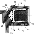
With reference to Fig. 2, as shown in the figure, the inlet connector 14 of valve has and is conical hole 70 slightly, and this hole 70 is communicated with the access road 58 that leads to valve chamber 56 (see figure 1)s.Bellmouth 70 has annular incision part 72 near its open end place.The inner end portion in hole 70 has and is suitable for locating the shoulder or flat 74 that presses.
With reference to Fig. 2 and 3, total filtration graticule mesh parts with cardinal principle cup-shaped structure by 76 expressions have outer cylinder surface 78, and this surface is taper, the bellmouth 70 in its size tight fit valve body 12.Cup-shaped graticule mesh parts 76 have the closed end that configuration is roughly plane surface, represent that with numbering 80 when with parts 76 patchholes 70, the circular periphery of plane surface 80 is positioned on the shoulder 74 of valve body 12.Flange near the cup-shaped parts 76 of open end has shoulder or protuberance 82, this protuberance apace kayser on the lower cut 72 in hole 70.The closed end 80 of cup-shaped parts 76 has many holes 84, and this hole distributes at a certain distance, and its size can make the particle greater than preliminary dimension be trapped on the surface of graticule mesh blind end.In presently preferred embodiment, the length-width ratio in hole is at least 0.8, and the interval of the center to center in graticule mesh hole preferably is its width or diameter 1.8 times at least.Its axial length of interior cylindrical surface of filtration graticule mesh cup and transverse width or diameter ratio are at least 1.0 in present preferred embodiment, and this cup is preferably whole to be made by moulded plastic.
Have annular protrusion or shoulder 90 on the contiguous open end of cup-shaped parts 76 or the interior cylindrical surface of its flange, this shoulder 90 is used to locate the flange 86 of cup-shaped filter screen 88.In preferred enforcement now, cup-shaped graticule mesh parts 76 at first are installed in the hole 70 of valve body 12, then screen pack 88 are mounted in it.But be understood that, if be ready, screen pack can be contained in earlier in the cup-shaped parts 76, the flange 86 of screen pack is positioned on the shoulder 90 of cup-shaped graticule mesh part, owing to form the sub-component of filter screen and graticule mesh, and then this sub-component be contained in the hole 70 of valve body.
Therefore the invention provides a kind of filtration graticule mesh that can be used for screen pack auxiliary or reserve, this screen pack is used for filtering the impurity particle thing of the fluid that enters valve.This graticule mesh is formed and is processed as whole cup-shaped parts, can be inserted in the inlet, and original screen pack then inserts in this graticule mesh.The structure of screen pack of the present invention can make graticule mesh still stay in the valve inlet under the situation that screen pack stops up and is removed, and therefore this graticule mesh even fluid flows through rapidly, also can provide some filtration measures when not having filter screen.
Though the present invention is illustrated above-mentioned illustrated embodiment, should be understood that the present invention can revise and modification, it only is subjected to the restriction of following claims.
Claims (11)
1. filtration graticule mesh that is used in valve inlet, comprise: the integrally formed single cup-shaped parts that are roughly, these parts have columnar inlet wall part and form the whole smooth end wall of cardinal principle with this wall part, (i) above-mentioned end wall portion has many holes at a certain distance, each hole has predetermined circulation area, so that hold back the particle of preliminary dimension; (ii) above-mentioned cylindrical wall partly has the main outer surface part that in axial direction forms taper;
2. graticule mesh as claimed in claim 1 is characterized in that the length-width ratio in each above-mentioned hole is at least 0.8.
3. graticule mesh as claimed in claim 1 is characterized in that, the distance of the center to center in above-mentioned hole is at least 1.8 times of its width.
4. filtration graticule mesh as claimed in claim 1 is characterized in that, the length-width ratio of the interior perimeter surface of above-mentioned cylindrical shape part is at least 1.0.
5. filtration graticule mesh as claimed in claim 1 is characterized in that, above-mentioned cylindrical wall part and above-mentioned end wall moulded plastic monolithic molding.
6. control system as claimed in claim 1 is characterized in that, above-mentioned total device comprises a rotating cam that is advanced by ratchet and pawl, and above-mentioned ratchet is connected in above-mentioned drive unit.
7. valve member comprises:
(a) valve body has the inlet that is fit to be connected on the fluid source, and this inlet communicates with valve chamber, and this valve chamber is communicated with outlet;
(b) valve member is configured in the above-mentioned valve chamber, can and fluid be flow through between the open position of above-mentioned inlet outlet in the closed position of blocking fluid between the above-mentioned entrance and exit and move;
(c) filter the graticule mesh parts, have configuration that is roughly cup-shaped integral body and the many holes that form on its closed end, above-mentioned graticule mesh parts assemble and are positioned in the above-mentioned inlet;
(d) be roughly cup-shaped screen pack, be contained in the above-mentioned cup-shaped graticule mesh, the mesh of above-mentioned filter screen is much thinner than the hole of above-mentioned graticule mesh.
8. valve member as claimed in claim 7 is characterized in that, above-mentioned graticule mesh parts form cannelure around its edge of opening, and the flange portion of above-mentioned screen pack is positioned in the above-mentioned groove.
9. the method for the fluid of valve is flow through in a filtration, and this valve has entrance and exit, and the improvement of method may further comprise the steps:
(a) on the bottom of above-mentioned cup shell or closed end, form the cup-shaped hole of single-piece;
(b) above-mentioned cup-shaped parts are installed in the above-mentioned entrance and exit one, the flow direction that the open end relative current of above-mentioned cup is crossed valve should be configured in the upstream in above-mentioned hole;
(c) above-mentioned cup-shaped screen pack is configured in the above-mentioned cup-shaped parts.
10. method as claimed in claim 9 is characterized in that, the above-mentioned steps that above-mentioned screen pack is installed comprises that the flange with above-mentioned screen pack openend is positioned in the above-mentioned cup-shaped parts.
11. method as claimed in claim 9, it is characterized in that, above-mentioned installation steps comprise that spring locks above-mentioned cup-shaped parts, electric control valve has integrally formed cup-shaped parts, on valve inlet, the cup-shaped screen pack of fine mesh is contained in the cup-shaped graticule mesh parts at the quick kayser of the porose graticule mesh of blind end, and is blocked during by user specially removal when it, the filtration graticule mesh is still stayed on its position, thereby the quick flow filtration of some dregs is provided.
Applications Claiming Priority (2)
| Application Number | Priority Date | Filing Date | Title |
|---|---|---|---|
| US08/424,026 US5582205A (en) | 1995-04-18 | 1995-04-18 | Filtering flow in a valve |
| US424,026 | 1995-04-18 |
Publications (1)
| Publication Number | Publication Date |
|---|---|
| CN1142407A true CN1142407A (en) | 1997-02-12 |
Family
ID=23681150
Family Applications (1)
| Application Number | Title | Priority Date | Filing Date |
|---|---|---|---|
| CN96105065A Pending CN1142407A (en) | 1995-04-18 | 1996-04-17 | Filtering flow in valve |
Country Status (7)
| Country | Link |
|---|---|
| US (1) | US5582205A (en) |
| EP (1) | EP0738532A3 (en) |
| JP (1) | JPH08332317A (en) |
| KR (1) | KR960038217A (en) |
| CN (1) | CN1142407A (en) |
| BR (1) | BR9601565A (en) |
| CA (1) | CA2173276A1 (en) |
Cited By (3)
| Publication number | Priority date | Publication date | Assignee | Title |
|---|---|---|---|---|
| CN100371048C (en) * | 2002-11-08 | 2008-02-27 | 麦斯克公司 | In-line screens for thermostatic valves |
| CN102003564A (en) * | 2009-08-28 | 2011-04-06 | 宇成电机工业株式会社 | Power-saving electromagnetic water supply valve |
| CN112313452A (en) * | 2018-07-04 | 2021-02-02 | Bsh家用电器有限公司 | Gas valve arrangement structure and gas stove |
Families Citing this family (15)
| Publication number | Priority date | Publication date | Assignee | Title |
|---|---|---|---|---|
| US7028704B2 (en) * | 1998-10-20 | 2006-04-18 | Morgantown Plastics Company | Fill valve |
| US6347616B1 (en) * | 2000-05-10 | 2002-02-19 | Delphi Technologies, Inc. | Solenoid valve for a vehicle carbon canister |
| US6722384B2 (en) * | 2001-06-08 | 2004-04-20 | Ronald L. Gates | Filter device for flush valves |
| US7040596B2 (en) * | 2002-11-29 | 2006-05-09 | Keihin Corporation | Solenoid valve for fuel cell |
| US7058989B2 (en) * | 2004-05-17 | 2006-06-13 | Domingos Victor L | Sports headband to reduce or prevent head injury |
| DE102008014025A1 (en) * | 2008-03-13 | 2009-09-17 | Boehringer Ingelheim Pharma Gmbh & Co. Kg | Inhaler and strainer for an inhaler |
| US7891370B1 (en) * | 2008-03-14 | 2011-02-22 | Hunter Industries, Inc. | Irrigation device with freeze member |
| PL2105540T3 (en) * | 2008-03-26 | 2014-12-31 | Geberit Int Ag | Servo-controlled water valve |
| KR101285748B1 (en) * | 2011-09-27 | 2013-07-18 | 우성전기공업 주식회사 | Solenoid value having fluid control function |
| DE102012217114B4 (en) | 2012-09-24 | 2022-06-15 | Robert Bosch Gmbh | Filter arrangement for a hydraulic valve |
| US9616388B2 (en) * | 2013-03-15 | 2017-04-11 | Culligan International Company | Reverse osmosis system with an automated modulated bypass |
| JP6105999B2 (en) * | 2013-03-27 | 2017-03-29 | 東芝キヤリア株式会社 | Strainer device, hot water supply device |
| CN103569926B (en) * | 2013-11-01 | 2016-01-20 | 广州达意隆包装机械股份有限公司 | Filling valve |
| RU2621456C2 (en) * | 2015-07-06 | 2017-06-06 | Российская Федерация, от имени которой выступает Министерство обороны Российской Федерации | Solenoid valve |
| CN108579183A (en) * | 2018-07-09 | 2018-09-28 | 苏州凯新分离科技有限公司 | A kind of pipe type filtering device with elasticity filtering buckle |
Family Cites Families (9)
| Publication number | Priority date | Publication date | Assignee | Title |
|---|---|---|---|---|
| US801093A (en) * | 1905-04-07 | 1905-10-03 | Jacob Koehler | Filtering-faucet. |
| US1626721A (en) * | 1924-07-26 | 1927-05-03 | Nonexplosive Corp | Safety attachment for tanks |
| US1898816A (en) * | 1929-12-18 | 1933-02-21 | George M Crossen | Valve |
| US2334802A (en) * | 1941-09-29 | 1943-11-23 | Zuckermann Isidore | Filter |
| US2936780A (en) * | 1956-04-02 | 1960-05-17 | Guardian Electric Mfg Co | Combination solenoid valve and pressure switch |
| FR1594785A (en) * | 1968-11-04 | 1970-06-08 | ||
| US4021354A (en) * | 1975-10-31 | 1977-05-03 | Bristol-Myers Company | Pressure filter |
| US4595500A (en) * | 1983-07-28 | 1986-06-17 | Mauro Galbiati | Filter for purifying drinkable and non-drinkable water |
| US5145145A (en) * | 1991-03-11 | 1992-09-08 | Eaton Corporation | Pilot operated electrically actuated value assembly |
-
1995
- 1995-04-18 US US08/424,026 patent/US5582205A/en not_active Expired - Fee Related
-
1996
- 1996-04-02 CA CA002173276A patent/CA2173276A1/en not_active Abandoned
- 1996-04-10 EP EP96105613A patent/EP0738532A3/en not_active Withdrawn
- 1996-04-17 KR KR1019960011556A patent/KR960038217A/en not_active Application Discontinuation
- 1996-04-17 CN CN96105065A patent/CN1142407A/en active Pending
- 1996-04-18 BR BR9601565-9A patent/BR9601565A/en not_active Application Discontinuation
- 1996-04-18 JP JP8120913A patent/JPH08332317A/en active Pending
Cited By (4)
| Publication number | Priority date | Publication date | Assignee | Title |
|---|---|---|---|---|
| CN100371048C (en) * | 2002-11-08 | 2008-02-27 | 麦斯克公司 | In-line screens for thermostatic valves |
| CN102003564A (en) * | 2009-08-28 | 2011-04-06 | 宇成电机工业株式会社 | Power-saving electromagnetic water supply valve |
| CN112313452A (en) * | 2018-07-04 | 2021-02-02 | Bsh家用电器有限公司 | Gas valve arrangement structure and gas stove |
| CN112313452B (en) * | 2018-07-04 | 2023-10-13 | Bsh家用电器有限公司 | Gas valve arrangement structure and gas stove |
Also Published As
| Publication number | Publication date |
|---|---|
| US5582205A (en) | 1996-12-10 |
| EP0738532A2 (en) | 1996-10-23 |
| CA2173276A1 (en) | 1996-10-19 |
| EP0738532A3 (en) | 1996-10-30 |
| KR960038217A (en) | 1996-11-21 |
| JPH08332317A (en) | 1996-12-17 |
| BR9601565A (en) | 1999-10-13 |
Similar Documents
| Publication | Publication Date | Title |
|---|---|---|
| CN1142407A (en) | Filtering flow in valve | |
| US6615858B2 (en) | Appliance water valve assembly and associated method | |
| CN103458985B (en) | The discharge liquid filter of being discharged by media implementation | |
| US6073904A (en) | Latching coil valve | |
| US3841489A (en) | Fluid filter | |
| US5887848A (en) | Flush valve bypass and filter | |
| US4261545A (en) | Flush valve piston having filtered orifice | |
| US6375833B1 (en) | Filter assembly with UV treatment, filter bypass, and clogging indicator | |
| CA2130656C (en) | Filter screen and method of making same | |
| US4036758A (en) | Fluid filter | |
| US5145145A (en) | Pilot operated electrically actuated value assembly | |
| US4621788A (en) | Solenoid valve | |
| US3890232A (en) | Fluid filter | |
| EP0207233B1 (en) | Straining and stop valve | |
| US5154394A (en) | Solenoid operated valve with improved flow control means | |
| US6758969B2 (en) | Magnetically enhanced oil filter apparatus | |
| US6378542B1 (en) | Flow control device having a lip seal and compressible bypass pads and associated method for operating an appliance water valve | |
| CA2040568C (en) | Diaphragm actuated valve assembly | |
| US4806258A (en) | Straining and stop valve | |
| US3368582A (en) | Pilot-operated valve including removable filter | |
| US7581649B2 (en) | Reverse flow spin-cleaning liquid filters | |
| US3334754A (en) | Filter head structure | |
| US4815497A (en) | Valve assembly and flow control therefor | |
| US6412645B1 (en) | Integrated filter and noise suppressor device for a water valve assembly and associated method for operating the same | |
| JPH10115382A (en) | Solenoid valve |
Legal Events
| Date | Code | Title | Description |
|---|---|---|---|
| C06 | Publication | ||
| PB01 | Publication | ||
| C10 | Entry into substantive examination | ||
| SE01 | Entry into force of request for substantive examination | ||
| C01 | Deemed withdrawal of patent application (patent law 1993) | ||
| WD01 | Invention patent application deemed withdrawn after publication |