CN114214906B - Road construction pretreatment device and construction method thereof - Google Patents
Road construction pretreatment device and construction method thereof Download PDFInfo
- Publication number
- CN114214906B CN114214906B CN202111635348.4A CN202111635348A CN114214906B CN 114214906 B CN114214906 B CN 114214906B CN 202111635348 A CN202111635348 A CN 202111635348A CN 114214906 B CN114214906 B CN 114214906B
- Authority
- CN
- China
- Prior art keywords
- frame body
- road
- groove
- cutting
- road construction
- Prior art date
- Legal status (The legal status is an assumption and is not a legal conclusion. Google has not performed a legal analysis and makes no representation as to the accuracy of the status listed.)
- Active
Links
Images


Classifications
-
- E—FIXED CONSTRUCTIONS
- E01—CONSTRUCTION OF ROADS, RAILWAYS, OR BRIDGES
- E01C—CONSTRUCTION OF, OR SURFACES FOR, ROADS, SPORTS GROUNDS, OR THE LIKE; MACHINES OR AUXILIARY TOOLS FOR CONSTRUCTION OR REPAIR
- E01C23/00—Auxiliary devices or arrangements for constructing, repairing, reconditioning, or taking-up road or like surfaces
- E01C23/06—Devices or arrangements for working the finished surface; Devices for repairing or reconditioning the surface of damaged paving; Recycling in place or on the road
- E01C23/09—Devices or arrangements for working the finished surface; Devices for repairing or reconditioning the surface of damaged paving; Recycling in place or on the road for forming cuts, grooves, or recesses, e.g. for making joints or channels for markings, for cutting-out sections to be removed; for cleaning, treating, or filling cuts, grooves, recesses, or fissures; for trimming paving edges
- E01C23/0906—Devices or arrangements for working the finished surface; Devices for repairing or reconditioning the surface of damaged paving; Recycling in place or on the road for forming cuts, grooves, or recesses, e.g. for making joints or channels for markings, for cutting-out sections to be removed; for cleaning, treating, or filling cuts, grooves, recesses, or fissures; for trimming paving edges for forming, opening-out, cleaning, drying or heating cuts, grooves, recesses or, excluding forming, cracks, e.g. cleaning by sand-blasting or air-jet ; for trimming paving edges
- E01C23/0926—Devices or arrangements for working the finished surface; Devices for repairing or reconditioning the surface of damaged paving; Recycling in place or on the road for forming cuts, grooves, or recesses, e.g. for making joints or channels for markings, for cutting-out sections to be removed; for cleaning, treating, or filling cuts, grooves, recesses, or fissures; for trimming paving edges for forming, opening-out, cleaning, drying or heating cuts, grooves, recesses or, excluding forming, cracks, e.g. cleaning by sand-blasting or air-jet ; for trimming paving edges with power-driven tools, e.g. vibrated, percussive cutters
- E01C23/0933—Devices or arrangements for working the finished surface; Devices for repairing or reconditioning the surface of damaged paving; Recycling in place or on the road for forming cuts, grooves, or recesses, e.g. for making joints or channels for markings, for cutting-out sections to be removed; for cleaning, treating, or filling cuts, grooves, recesses, or fissures; for trimming paving edges for forming, opening-out, cleaning, drying or heating cuts, grooves, recesses or, excluding forming, cracks, e.g. cleaning by sand-blasting or air-jet ; for trimming paving edges with power-driven tools, e.g. vibrated, percussive cutters rotary, e.g. circular-saw joint cutters
-
- E—FIXED CONSTRUCTIONS
- E01—CONSTRUCTION OF ROADS, RAILWAYS, OR BRIDGES
- E01C—CONSTRUCTION OF, OR SURFACES FOR, ROADS, SPORTS GROUNDS, OR THE LIKE; MACHINES OR AUXILIARY TOOLS FOR CONSTRUCTION OR REPAIR
- E01C23/00—Auxiliary devices or arrangements for constructing, repairing, reconditioning, or taking-up road or like surfaces
- E01C23/06—Devices or arrangements for working the finished surface; Devices for repairing or reconditioning the surface of damaged paving; Recycling in place or on the road
- E01C23/09—Devices or arrangements for working the finished surface; Devices for repairing or reconditioning the surface of damaged paving; Recycling in place or on the road for forming cuts, grooves, or recesses, e.g. for making joints or channels for markings, for cutting-out sections to be removed; for cleaning, treating, or filling cuts, grooves, recesses, or fissures; for trimming paving edges
- E01C23/096—Devices or arrangements for working the finished surface; Devices for repairing or reconditioning the surface of damaged paving; Recycling in place or on the road for forming cuts, grooves, or recesses, e.g. for making joints or channels for markings, for cutting-out sections to be removed; for cleaning, treating, or filling cuts, grooves, recesses, or fissures; for trimming paving edges for forming, opening-out, cleaning, drying or heating and filling
-
- E—FIXED CONSTRUCTIONS
- E01—CONSTRUCTION OF ROADS, RAILWAYS, OR BRIDGES
- E01C—CONSTRUCTION OF, OR SURFACES FOR, ROADS, SPORTS GROUNDS, OR THE LIKE; MACHINES OR AUXILIARY TOOLS FOR CONSTRUCTION OR REPAIR
- E01C23/00—Auxiliary devices or arrangements for constructing, repairing, reconditioning, or taking-up road or like surfaces
- E01C23/06—Devices or arrangements for working the finished surface; Devices for repairing or reconditioning the surface of damaged paving; Recycling in place or on the road
- E01C23/09—Devices or arrangements for working the finished surface; Devices for repairing or reconditioning the surface of damaged paving; Recycling in place or on the road for forming cuts, grooves, or recesses, e.g. for making joints or channels for markings, for cutting-out sections to be removed; for cleaning, treating, or filling cuts, grooves, recesses, or fissures; for trimming paving edges
- E01C23/0966—Devices or arrangements for working the finished surface; Devices for repairing or reconditioning the surface of damaged paving; Recycling in place or on the road for forming cuts, grooves, or recesses, e.g. for making joints or channels for markings, for cutting-out sections to be removed; for cleaning, treating, or filling cuts, grooves, recesses, or fissures; for trimming paving edges for filling or priming, with or without working the surface of the filling or applying particulate material thereto, e.g. for filling the joints of stone-sett paving
- E01C23/0973—Devices or arrangements for working the finished surface; Devices for repairing or reconditioning the surface of damaged paving; Recycling in place or on the road for forming cuts, grooves, or recesses, e.g. for making joints or channels for markings, for cutting-out sections to be removed; for cleaning, treating, or filling cuts, grooves, recesses, or fissures; for trimming paving edges for filling or priming, with or without working the surface of the filling or applying particulate material thereto, e.g. for filling the joints of stone-sett paving with liquid or semi-liquid materials, e.g. crack sealants
-
- E—FIXED CONSTRUCTIONS
- E01—CONSTRUCTION OF ROADS, RAILWAYS, OR BRIDGES
- E01C—CONSTRUCTION OF, OR SURFACES FOR, ROADS, SPORTS GROUNDS, OR THE LIKE; MACHINES OR AUXILIARY TOOLS FOR CONSTRUCTION OR REPAIR
- E01C23/00—Auxiliary devices or arrangements for constructing, repairing, reconditioning, or taking-up road or like surfaces
- E01C23/06—Devices or arrangements for working the finished surface; Devices for repairing or reconditioning the surface of damaged paving; Recycling in place or on the road
- E01C23/12—Devices or arrangements for working the finished surface; Devices for repairing or reconditioning the surface of damaged paving; Recycling in place or on the road for taking-up, tearing-up, or full-depth breaking-up paving, e.g. sett extractor
- E01C23/122—Devices or arrangements for working the finished surface; Devices for repairing or reconditioning the surface of damaged paving; Recycling in place or on the road for taking-up, tearing-up, or full-depth breaking-up paving, e.g. sett extractor with power-driven tools, e.g. oscillated hammer apparatus
- E01C23/127—Devices or arrangements for working the finished surface; Devices for repairing or reconditioning the surface of damaged paving; Recycling in place or on the road for taking-up, tearing-up, or full-depth breaking-up paving, e.g. sett extractor with power-driven tools, e.g. oscillated hammer apparatus rotary, e.g. rotary hammers
Abstract
The invention belongs to the technical field of road construction, and particularly relates to a road construction pretreatment device and a construction method thereof, wherein the road construction pretreatment device comprises a frame body, a cutting mechanism and a crack pouring mechanism; according to the invention, by arranging the cutting device and the frame body, the gravity of the frame body and the crack pouring mechanism above the frame body is utilized to promote the cutting and cuttage of the cutting wheel and the inserted rod, so that the cutting and removing effects of the road construction pretreatment device on an asphalt layer on a road surface are more convenient and faster, and meanwhile, the characteristic of forward movement of the road construction pretreatment device is utilized to match with the guide plate to guide and recover cut and broken stones and broken asphalt, so that the repair groove can be effectively cleaned, the crack pouring mechanism can conveniently pour mortar into the repair groove, the cutting, cleaning and mortar pouring are simultaneously carried out, so that workers can effectively treat road gaps, the operation of the workers is facilitated, the repair efficiency is accelerated, and the labor intensity of the workers can be effectively reduced.
Description
Technical Field
The invention belongs to the technical field of road construction, and particularly relates to a road construction pretreatment device and a construction method thereof.
Background
In the prior art, when a road is set up or used for a long time, cracks with different lengths often appear on the road surface, if repair measures are not timely taken for the cracks, the cracks can be gradually aggravated, the quality of the road surface can be further influenced, the service life of the road surface is reduced, and even potential safety hazards are brought.
A road, bridge road surface crack repairing preprocessing device that china patent issued, application number: CN2019102316586, including frame, strip suction nozzle, linking frame, sealing ring, transmission unit assembly and drive assembly. The top of the frame is provided with flat arms which are opposite and extend horizontally. The strip-shaped suction nozzle is arranged below the flat arm, and the bottom surface of the strip-shaped suction nozzle is provided with a strip-shaped sinking groove. The connecting frame is fixed on the upper part of the strip-shaped suction nozzle. The seal is arranged around the bottom edge of the strip-shaped suction nozzle. The transmission unit assembly is arranged between the connecting frame and the flat arm. The driving assembly is arranged on the flat arm and matched with the transmission unit assembly, and can enable the strip-shaped suction nozzle to move up and down, so that the sealing ring is switched between two states of being tightly pressed on a road surface and forming a gap with the road surface. A dust suction device is fixedly arranged above the trailing arm, and a conveying conduit of the dust suction device is communicated with the strip-shaped sinking groove. It helps improving because of the relatively poor problem of colloid and road surface combination effect that exists thoroughly to crack clearance, reduces the flying dust that produces in the construction operation, plays the purpose of improvement to operating personnel's operational environment, but the device can't freely remove when carrying out the dust absorption, and then leads to the cleaning work comparatively slowly.
In view of this, the present invention provides a road construction pretreatment device and a construction method thereof for solving the above technical problems.
Disclosure of Invention
The invention provides a road construction pretreatment device and a construction method thereof, aiming at overcoming the defects of the prior art and solving the problems of complex pretreatment process and low working efficiency in the prior art before paving an asphalt layer in road gap repair.
The technical scheme adopted by the invention for solving the technical problems is as follows: the invention relates to a road construction pretreatment device, which comprises a frame body, a cutting mechanism and a crack pouring mechanism, wherein the frame body is provided with a plurality of grooves;
the frame body is a car hopper-shaped mechanism body with a recovery cavity arranged inside; one end of the frame body is provided with a handrail; the bottom of one end, close to the handrail, of the frame body is designed in a conical shape; the frame body is positioned below the recovery cavity and is provided with a power cavity; a power device is arranged in the power cavity through a telescopic rod; the power cavity is arranged at openings at two sides of the frame body; the opening of the power cavity is rotatably connected with a rotating shaft; the rotating shaft extends into the power cavity; the rotating shaft is positioned in the power cavity and is in transmission with the power device through a gear set; one end of the rotating shaft, which is positioned outside the power cavity, is fixedly connected with a wheel; one end of the frame body, which is far away from the conical bottom, is provided with an installation groove; the frame body is positioned on one side of the mounting groove, which is far away from the handrail, and is hinged with a supporting wheel through a guide rod;
the cutting mechanism comprises an inserted link, an electric motor and a cutting wheel; the bottom of the frame body is positioned on one side of the mounting groove, which is far away from the power cavity, and is fixedly connected with a connecting plate; the connecting plate is rotatably connected with a connecting shaft; the two ends of the connecting shaft are fixedly connected with inserting rods; the inserted rods are all L-shaped rod-shaped structures; the end, far away from the connecting shaft, of the inserted rod is in a pointed conical design; one end of the inserted rod, which is close to the connecting shaft, is designed in a telescopic manner; the inserted rods are connected with supporting plates in a sliding manner; one sides of the supporting plates, which are far away from each other, are rotatably connected with cutting wheels through guide rods; one sides of the supporting plates, which are close to each other, are fixedly connected with electric motors through guide plates; the electric motor is connected with the cutting wheel through a guide rod; the diameters of the cutting wheels are all larger than the lengths of two L-shaped ends of the inserted bar; the two cutting wheels are designed in a conical shape, and the minimum ends of the conical shapes are close to each other; an electric push rod is hinged on the frame body; the electric push rod is hinged with one end of the inserted link, which is close to the connecting shaft; a connecting piece is rotationally connected in the mounting groove; the connecting piece is designed in a T shape; a guide plate is arranged in the mounting groove; a first sliding groove is formed in one side, close to the connecting piece, of the guide plate; the first sliding chute is in a T-shaped design; one end of the connecting piece, which is far away from the rotating point, is connected in the first sliding chute in a sliding manner; one end of the guide plate, which is close to the inserted link, is hinged with the middle part of the inserted link through a guide rod; in the initial state, the electric push rod is in a contraction state, one side of the inserted rod is tightly attached to the bottom of the frame body, and the guide rod is accommodated in the recovery cavity through the installation groove;
the crack pouring mechanism comprises a mud groove; the mud groove is fixedly connected to the upper side of one end of the frame body, which is far away from the wheel; an opening is formed above the mud groove, and a sealing cover is arranged at the opening; cement mortar is stored in the mud groove; the bottom of the slurry tank is fixedly connected with a crack pouring pipe; the seam filling pipe penetrates through the frame body and extends to the bottom of the frame body;
in the prior art, when a road is set up or used for a long time, cracks with different lengths often appear on the road surface, if repair measures are not timely taken for the cracks, the cracks gradually increase, the quality of the road surface is further influenced, the service life of the road surface is reduced, and even potential safety hazards are caused, when the road surface cracks on the road are repaired at present, a cutting machine is required to cut off an asphalt layer around the cracks, then dust and broken sand in the cracks are removed, the cracks are filled with filling foam or quartz sand, a certain distance is reserved between the upper end of a filler and a crack port, and finally filling and pressing of asphalt cold materials are carried out on the upper portions of the cracks, so that various operation devices are involved in the operation process, the operation process is troublesome and long in time consumption, and the cutting machines are mostly single-wheel cutting, so that the road cutting consumes long time, and the rapid repair of the road cracks is inconvenient;
when the invention works, through arranging the frame body, the cutting mechanism and the crack pouring mechanism, when the road crack is treated, firstly, the road construction pretreatment device is moved to the crack position of the road, the supporting wheel is manually pushed towards the direction of the handrail after the groove pit is dug on the road surface, the supporting wheel is enabled to rotate towards the direction of the inserted link, and the electric motor is started at the moment, the electric motor drives the cutting wheel to rotate, the front end of the road construction pretreatment device downwards presses the asphalt road surface under the action of gravity by adopting a mode of gradually loosening the handrail, the cut groove pit on the road surface is widened by the cutting wheel under the cutting action of the cutting wheel, the cutting mechanism is enabled to be settled towards the inside of the groove, the inserted link at the inner side of the double cutting wheels acts on the road at the inner side of the double cutting wheels under the action of gravity along with the settlement of the cutting mechanism, and further presses the cut asphalt blocks, finally, the cutting wheel and the inserted bar enter the pit slot, at the moment, the electric push rod extends out to play a role in pushing the inserted bar by starting the electric push rod, so that the electric push rod drives the inserted bar to rotate, the rotating inserted bar is finally parallel to the bottom of the frame body, simultaneously, along with the rotation of the inserted bar, a guide plate hinged between the inserted bar is subjected to the double limiting effects of the inserted bar and a connecting piece, so that the inclination angle of the guide plate is increased, the support wheel plays a role in pushing the support wheel in the rotating process of the inserted bar, when the inserted bar is parallel to the frame body, the support wheel is also parallel to the frame body, because the inserted bar is in a telescopic design, the rotating inserted bar exceeds the length of the support wheel, and under the asphalt layer in the rotating process, along with the starting of the power device, the power device transmits through a gear set, so as to drive the rotating shaft and the wheels to rotate, and further, the frame body is driven to slowly move forwards through the friction between the wheels and the ground, the cutting wheel firstly cuts the ground asphalt layer in the process of moving forwards, then the inserted bar gradually extends into the lower part of the cut asphalt layer, the inserted bar plays a role of lifting upwards on the cut asphalt layer along with the forward movement of the device, so that the asphalt layer is broken, the bottom of the guide plate is connected with the inserted bar along with the movement of the device, so that the broken asphalt layer is gradually stacked on the guide plate and enters the recovery cavity through the inclined guide plate under the mutual pushing action, the recovery of the broken asphalt layer and the broken stones is completed, the device continuously moves forwards, so that the repair groove is formed on the road, when the crack filling pipe on the frame body moves to the upper part of the repair groove, cement mortar is filled into the repair groove through the crack filling pipe, namely the pretreatment of crack repair is completed, through setting up cutting device and support body, the gravity that utilizes support body and support body top cementation mechanism plays the promotion effect to the cutting and the cuttage of cutting wheel and inserted bar, and then it is more convenient to make the cutting clearance effect on the pitch layer on the road surface of road construction preprocessing device, it is swift, the characteristic cooperation deflector that utilizes road construction preprocessing device to move forward simultaneously is to the cutting, cracked stone, garrulous pitch plays the direction, retrieve, can effectually play the clearance effect to repairing the groove, the cementation of fissures mechanism to repairing the inslot mortar of being convenient for, will cut, clearance and mortar fill carry out the workman to the processing in road gap of being convenient for that can effectually simultaneously, the workman of being convenient for operates, can also effectual reduction workman's intensity of labour when accelerating repair efficiency.
Preferably, the frame body is provided with lifting grooves at openings at two ends of the power cavity; lifting plates are connected in the lifting grooves in a sliding manner; the lifting plate is rotationally connected with the rotating shaft; the part of the lifting plate, which is positioned in the lifting groove, is fixedly connected with a hydraulic lifting device; the top end of the hydraulic lifting device is fixedly connected with the frame body; both ends of the handrail extend into the lifting groove; one end of the handrail, which is positioned in the lifting groove, is fixedly connected with the output end of the hydraulic lifting device and is used for driving a hydraulic oil cylinder in the hydraulic lifting device to rise and fall through the rotation of the handrail; the bottom of the frame body is fixedly connected with a rubber disc; the rubber disc is in a rectangular design; a limiting plate is fixedly connected to one side of the rubber disc, which is far away from the frame body; the width of the limiting plate is the same as the distance between the two cutting wheels; the crack pouring pipe extends into the rubber disc and is arranged at an opening on the surface of the rubber disc; the seam filling pipe is arranged in the rubber disc, and an opening of the seam filling pipe is inclined towards the armrest direction;
the during operation, along with road construction preprocessing device's motion, the repair groove coincidence that limiting plate on the rubber dish seted up gradually with road construction preprocessing device, after both coincidence completely, through manual rocking handrail from top to bottom, and then make the handrail drive hydraulic lifting device descend, and then make support body and wheel relative movement, make the support body move down, and then make the limiting plate on the rubber dish on the support body stretch into and repair the inslot, open the cementation of fissures pipe this moment, mortar flows downwards in the cementation of fissures pipe, and then get into and repair in the groove, and the limiting displacement who receives the limiting plate at the repair inslot possesses certain height, simultaneously along with the continuous removal of device, the limiting plate can also play the floating to repairing inslot mortar, the effect that compresses tightly, and then make the cement mortar compactness of pouring higher.
Preferably, the frame body is provided with an adsorption cavity at one side of the power cavity, which is far away from the handrail; a dust suction device is fixedly connected in the adsorption cavity; the air outlet end of the dust suction device extends to the upper part of the mud groove through the air duct; one side of the rubber disc, which is far away from the handrail, is fixedly connected with a baffle; the width of the baffle is consistent with that of the limiting plate; the air suction end of the dust suction device penetrates through the rubber disc through the air suction pipe; the air exhaust pipe is positioned between the seam filling pipe and the baffle and is provided with an opening, and the opening direction is far away from the seam filling pipe;
the during operation, through setting up dust extraction and baffle, descend downwards when the support body, and then make rubber disc and ground contact, the limiting plate stretches into and repairs the inslot, the exhaust tube stretches into equally and repairs the inslot, the baffle stretches into and repairs the inslot and shelter from to repairing groove direction of height, and then make the external passageway diameter of admitting air in to the exhaust tube through repairing the groove opening and reduce, and then the suction effect that makes the exhaust tube is to repairing the piece of tank bottom portion, the gravel possesses stronger extraction effect, the setting of rubber disc is to repairing groove top open-ended leakproofness reinforcing simultaneously, and then make the negative pressure appeal reinforcing of dust extraction to repairing the groove formation, and then make the clearance effect go on more convenient, and then the mortar that fills for the cementation of crack pouring pipe of keeping away from the direction of motion is inseparabler with repairing the groove combination.
Preferably, the baffle is in an L-shaped design; the baffle extends to the cutting wheel; the rubber disc is fixedly connected with the frame body through a positioning plate; the positioning plate is provided with uniformly distributed rotating holes; the rotating rods are rotatably connected in the rotating holes; both ends of the rotating rod extend to both sides of the positioning plate; a plurality of rotating rods are sleeved with rubber belts together; the rubber belt is made of elastic wear-resistant rubber material; the rubber belt is used for matching with the rubber disc to realize a sealing effect;
during operation, through the shape that sets up the baffle, the inlet channel that makes baffle and repair groove form extends to cutting wheel department, and then the effectual negative pressure gravitation that makes dust extraction form acts on the cutting wheel, and then the effectual micronic dust that will cut the wheel formation draws in the exhaust tube, and then avoid the job site to fly upward because of cutting, and then the dirty and disorderly phenomenon of effectual reduction job site, simultaneously because the support body is in the state of constantly antedisplacement, the rubber dish receives wearing and tearing easily and then leads to reducing to the effect of repairing the groove, through setting up locating plate and rubber tape, utilize constantly to rotate the rubber tape that gos forward along with the bull stick, make the friction between rubber tape and the ground reduce, and then utilize rubber tape cooperation rubber disk, effectual reinforcing seal effect, and then reinforcing negative pressure gravitation is to the effect of repairing the groove.
Preferably, the rubber belt is internally provided with a first cavity; the lifting groove is positioned on the side wall of the hydraulic lifting device and fixedly connected with a squeezing bag; the extrusion bag and the first cavity are designed to be communicated through a catheter;
during operation, through setting up the extrusion bag, descend as hydraulic pressure elevating gear, and then when making the support body descend to the wheel direction, the extrusion bag in the lift inslot is compressed force and is contracted, and then makes the extrusion bag carry inside gas to in the first cavity, and then makes the gas increase in the first cavity, makes the rubber tape inflation, and then makes the laminating effect reinforcing of rubber tape and ground, and then the sealing strength in effectual reinforcing repair groove.
Preferably, the supporting plate is provided with a second sliding groove; a moving plate is connected in the second sliding groove in a sliding manner; the cross sections of the second sliding groove and the movable plate are both in T-shaped design; one side of the moving plate, which is far away from the supporting plate, is rotatably connected with a rotating roller; the rotating roller is made of steel materials;
the during operation, through setting up the live-rollers, the in-process live-rollers that removes forward at road construction preprocessing device rolls subaerial, and when upwards lifting along with the effect that receives the inserted bar gradually by the pitch layer of cutting, the live-rollers plays spacing effect to it, and then makes pitch layer both ends receive upwards and decurrent dynamics respectively, and then effectual reinforcing is to the rupture on pitch layer, crushing effect, and then the deflector pitch fragment of being convenient for guides, is convenient for remove to retrieving the intracavity.
A construction method of a road construction pretreatment device, comprising the steps of:
s1: cleaning stones and sundries on the surface of a road, using a marking tape to mark the cracks of the road in a segmented manner, enabling the cracks of the road to be positioned in a rectangular frame marked by the marking tape, and controlling the rectangular frame marked by the marking tape to be consistent with the distance between two cutting wheels on a road construction pretreatment device;
s2: manually cutting one end of the rectangular frame to enable the thickness of a cutting pit to be consistent with that of a road asphalt layer, pushing the road construction pretreatment device to operate at the cutting position, manually pushing the supporting wheel to the direction of the handrail, and starting the electric motor to enable the electric motor to drive the cutting wheel to rotate to cut the road pavement;
s3: the front end of the road construction pretreatment device downwards presses the asphalt pavement under the action of gravity by gradually loosening the handrail, the cutting wheel and the inserted bar gradually extend into the groove pit under the cutting action of the cutting wheel, and the electric push rod is controlled to extend out in the groove pit;
s4: the electric push rod is completely extended out, the inserted link is parallel to the ground, the power device is controlled to work to drive the road construction pretreatment device to move slowly, a repairing groove is cut on the road in the moving process, and at the moment, the hydraulic lifting device descends by rotating the handrail up and down, so that the frame body is completely descended to the ground, and the rubber disc is extended into the repairing groove;
s5: along with the removal of road construction preprocessing device, control dust extraction starts, clears up and cement mortar pours into to repairing the groove, puts aside road construction preprocessing device after pouring and finishes, treats that cement mortar solidifies the back naturally, uses pitch mixed gravel to fill in concrete layer top layer formation pitch layer, accomplishes the repair of road crack promptly.
Preferably, the filling of the asphalt layer in S5 is layered filling, and the filled asphalt layer is pressed by a road roller in a gap between the layered filling; the final height of the asphalt layer exceeds the road surface by 0.5-1cm, and the edge of the asphalt layer is arc-shaped under the action of a road roller;
the during operation, through successive layer suppression, the gap distance between the pitch layer that makes the formation is littleer, and then makes the density reinforcing on the pitch layer that makes, and the infiltration rate of effectual reduction rainwater highly is higher than the road surface with the pitch layer simultaneously, can effectually avoid permeating in the not completely fixed pitch layer of rainwater flow direction in rainwater weather, and then plays the destruction effect to the combination between cement mortar layer and the pitch layer of below.
Preferably, the asphalt layer is coated with the interface agent on the side wall of the repairing groove by a brush before being laid; during operation, the bonding effect between the asphalt layer and the original asphalt layer can be effectively enhanced by coating the interface agent, so that the bonding degree between the repair part and the original road is stronger, and new cracks are avoided.
Preferably, the cement mortar prepared by mixing cement, sand, water, an expanding agent and a water reducing agent in a ratio of 1: 0.5: 1: 0.15: 0.01 is used as the cement mortar in S5; the cement mortar is used for enhancing the strength of the base layer.
The invention has the following beneficial effects:
1. according to the road construction pretreatment device and the construction method thereof, the cutting device and the frame body are arranged, the gravity of the frame body and the crack pouring mechanism above the frame body is utilized to promote the cutting and the cuttage of the cutting wheel and the insertion rod, so that the road construction pretreatment device can cut and remove asphalt layers on the road surface more conveniently and quickly, meanwhile, the characteristic that the road construction pretreatment device moves forwards is utilized to match with the guide plate to guide and recycle cut and broken stones and broken asphalt, the repair groove can be effectively cleaned, the crack pouring mechanism can conveniently pour mortar into the repair groove, the cutting, the cleaning and the mortar pouring can be simultaneously carried out, workers can effectively and conveniently treat road gaps, the operation of the workers is facilitated, the repair efficiency is accelerated, and the labor intensity of the workers can be effectively reduced.
2. According to the road construction pretreatment device and the construction method thereof, the rotating roller is arranged, so that the rotating roller rolls on the ground in the forward moving process of the road construction pretreatment device, and when the cut asphalt layer is lifted upwards gradually under the action of the insertion rod, the rotating roller has a limiting effect on the cut asphalt layer, so that the two ends of the asphalt layer are respectively stressed upwards and downwards, the breaking and crushing effects on the asphalt layer are effectively enhanced, and the guide plate asphalt fragments are conveniently guided and conveniently move to the recovery cavity.
Drawings
The invention will be further described with reference to the accompanying drawings.
FIG. 1 is a flow chart of a method of the present invention;
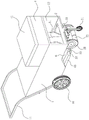
FIG. 2 is a front view of the road construction pretreatment device;
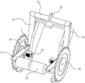
FIG. 3 is an expanded view of the road construction pretreatment device;
FIG. 4 is a front view of the cutting mechanism;
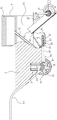
FIG. 5 is a partial cross-sectional view of a roadway construction preparation device;
FIG. 6 is a partial cross-sectional view of a roadway construction pretreatment device;
in the figure: the device comprises a frame body 1, an armrest 11, a recovery cavity 12, a power cavity 13, a power device 14, a rotating shaft 15, wheels 16, a mounting groove 2, a supporting wheel 21, a connecting plate 22, a connecting shaft 23, an inserting rod 24, a cutting wheel 25, an electric motor 26, an electric push rod 27, a supporting plate 28, a connecting piece 3, a guide plate 31, a first sliding groove 32, a mud groove 4, a sealing cover 41, a sewing pipe 42, a lifting groove 5, a lifting plate 51, a hydraulic lifting device 52, a rubber disc 53, a limiting plate 54, an adsorption cavity 55, a dust suction device 56, a baffle 57, an air suction pipe 58, a positioning plate 6, a rotating hole 61, a rotating rod 62, a rubber belt 63, a first cavity 64, an extrusion bag 65, a second sliding groove 7, a moving plate 71 and a rotating roller 72.
Detailed Description
In order to make the technical means, the creation characteristics, the achievement purposes and the effects of the invention easy to understand, the invention is further described with the specific embodiments.
As shown in fig. 1 to 6, the pretreatment device for road construction comprises a frame body 1, a cutting mechanism and a crack pouring mechanism;
the frame body 1 is a car hopper-shaped mechanism body with a recovery cavity 12 formed inside; one end of the frame body 1 is provided with a handrail 11; the bottom of one end, close to the handrail 11, of the frame body 1 is designed to be conical; a power cavity 13 is formed below the recovery cavity 12 of the frame body 1; a power device 14 is arranged in the power cavity 13 through a telescopic rod; the power cavity 13 is positioned at the openings at the two sides of the frame body 1; the opening of the power cavity 13 is rotatably connected with a rotating shaft 15; the rotating shaft 15 extends into the power cavity 13; the rotating shaft 15 is positioned in the power cavity 13 and is in transmission with the power device 14 through a gear set; one end of the rotating shaft 15, which is positioned outside the power cavity 13, is fixedly connected with a wheel 16; one end of the frame body 1, which is far away from the conical bottom, is provided with an installation groove 2; the support body 1 is positioned on one side of the installation groove 2 away from the handrail 11 and is hinged with a supporting wheel 21 through a guide rod;
the cutting mechanism comprises a plunger 24, an electric motor 26 and a cutting wheel 25; the bottom of the frame body 1 is positioned on one side of the mounting groove 2 away from the power cavity 13 and is fixedly connected with a connecting plate 22; the connecting plate 22 is rotatably connected with a connecting shaft 23; the two ends of the connecting shaft 23 are fixedly connected with inserting rods 24; the inserted rods 24 are all L-shaped rod-shaped structures; the end of the inserted rod 24, which is far away from the connecting shaft 23, is in a pointed conical design; one end of the inserted rod 24 close to the connecting shaft 23 is in a telescopic design; the inserted rods 24 are all connected with supporting plates 28 in a sliding manner; the sides, far away from each other, of the supporting plates 28 are rotatably connected with cutting wheels 25 through guide rods; the electric motors 26 are fixedly connected to the sides, close to each other, of the supporting plates 28 through guide plates; the electric motor 26 and the cutting wheel 25 are connected through a guide rod; the diameters of the cutting wheels 25 are all larger than the lengths of the two L-shaped ends of the insertion rod 24; the two cutting wheels 25 are both designed in a conical shape, and the minimum ends of the conical shapes are close to each other; an electric push rod 27 is hinged on the frame body 1; the electric push rod 27 is hinged with one end of the inserted link 24 close to the connecting shaft 23; a connecting piece 3 is rotationally connected in the mounting groove 2; the connecting piece 3"T' is designed in a shape; a guide plate 31 is arranged in the mounting groove 2; a first sliding chute 32 is formed in one side, close to the connecting piece 3, of the guide plate 31; the first chute 32 is of a T-shaped design; one end of the connecting piece 3, which is far away from the rotating point, is connected in the first sliding chute 32 in a sliding manner; one end of the guide plate 31 close to the inserted link 24 is hinged with the middle part of the inserted link 24 through a guide rod; in the initial state, the electric push rod 27 is in a contraction state, one side of the inserted link 24 is tightly attached to the bottom of the frame body 1, and the guide rod is accommodated in the recovery cavity 12 through the installation groove 2;
the crack pouring mechanism comprises a mud groove 4; the mud groove 4 is fixedly connected to the upper side of one end of the frame body 1 far away from the wheel 16; an opening is formed above the mud groove 4, and a sealing cover 41 is arranged at the opening; cement mortar is stored in the mud groove 4; the bottom of the mud groove 4 is fixedly connected with a crack pouring pipe 42; the seam filling pipe 42 penetrates through the frame body 1 and extends to the bottom of the frame body 1;
in the prior art, when a road is established or used for a long time, cracks with different lengths often appear on the road surface, if repair measures are not taken timely for the cracks, the cracks are gradually aggravated, the quality of the road surface is affected, the service life of the road surface is reduced, and even potential safety hazards are brought, when the road surface cracks on the road are repaired currently, an asphalt layer around the cracks needs to be cut off by a cutting machine firstly, then dust and broken sand in the cracks are removed, the cracks are filled by filling foam or quartz sand, a certain distance is reserved between the upper end of a filler and a crack port, and finally, filling and pressing of asphalt cold materials are carried out on the upper portions of the cracks, various operating devices are involved in the operating process, the actual operating process is troublesome and long in time consumption, and the road cutting time consumption is long due to the fact that the cutting machine is mostly used for a single wheel, and the rapid repair of the road cracks is inconvenient;
when the invention works, through arranging the frame body 1, the cutting mechanism and the crack pouring mechanism, when the road crack is treated, firstly, the road construction pretreatment device is moved to the crack position of the road, the supporting wheel 21 is manually pushed towards the handrail 11 after the groove pit is cut on the road surface, the supporting wheel 21 is enabled to rotate towards the insertion rod 24, and the electric motor 26 is started at the moment, the electric motor 26 drives the cutting wheel 25 to rotate, the handrail 11 is gradually loosened, the front end of the road construction pretreatment device downwards presses the asphalt road surface under the action of gravity, the cutting wheel 25 expands the cut groove pit on the road surface under the cutting action of the cutting wheel 25, the cutting mechanism is enabled to subside towards the groove pit, the insertion rod 24 positioned at the inner side of the double cutting wheel 25 acts on the road at the inner side of the double cutting wheel 25 under the action of gravity along with the settlement of the cutting mechanism, then the cut asphalt blocks are pressed, finally the cutting wheel 25 and the inserting rod 24 enter the pit slot, at the moment, the electric push rod 27 is started, the electric push rod 27 extends out to play a role in pushing the inserting rod 24, further, the electric push rod 27 drives the inserting rod 24 to rotate, the rotating inserting rod 24 is finally parallel to the bottom of the frame body 1, meanwhile, along with the rotation of the inserting rod 24, a guide plate 31 hinged between the inserting rod 24 and the inserting rod 24 is subjected to the double limiting effect of the inserting rod 24 and a connecting piece 3, further, the inclination angle of the guide plate 31 is increased, the supporting wheel 21 is pushed in the rotating process of the inserting rod 24, when the inserting rod 24 is parallel to the frame body 1, the supporting wheel 21 is parallel to the frame body 1, because the inserting rod 24 is in a telescopic design, the rotating inserting rod 24 exceeds the length of the supporting wheel 21, and is inserted below an asphalt layer in the rotating process, along with the starting of the power device 14, the power device 14 is driven by a gear set, thereby driving the rotating shaft 15 and the wheels 16 to rotate, further driving the frame body 1 to slowly move forward through the friction between the wheels 16 and the ground, the cutting wheel 25 firstly cuts the asphalt layer on the ground in the process of moving forwards, then the inserted rod 24 gradually extends into the lower part of the cut asphalt layer, and as the device moves forwards, the inserted rod 24 plays a role of lifting upwards the cut asphalt layer, and thus the asphalt layer is broken, as the device moves, the bottom of the guide plate 31 is connected with the inserted rod 24, the crushed asphalt layer is gradually accumulated on the guide plate 31 and enters the recovery cavity 12 through the inclined guide plate 31 under the mutual pushing action, the recovery of the crushed asphalt layer and the crushed stone is completed, and the crushed asphalt layer and the crushed stone move forwards continuously along with the device, thereby forming a repair groove on the road, when the crack pouring pipe 42 on the frame body 1 moves to the upper part of the repair groove, filling cement mortar into the repair groove through the crack pouring pipe 42, namely, the pretreatment of crack repair is finished, the cutting device and the frame body 1 are arranged, the gravity of the crack pouring mechanism above the frame body 1 and the frame body 1 is utilized to promote the cutting and cuttage of the cutting wheel 25 and the inserted link 24, so that the cutting and removing function of the road construction pretreatment device on the asphalt layer on the road surface is more convenient and faster, meanwhile, the characteristic that the road construction pretreatment device moves forwards is utilized to match with the guide plate 31 to guide and recycle the cut and cracked stones and crushed asphalt, can be effectual play the cleaning action to repairing the groove, the crack pouring mechanism of being convenient for pours the mortar into to repairing the inslot, will cut, clear up and the mortar pours into and carries out simultaneously can effectually be convenient for the workman to the processing in road gap, and the workman of being convenient for operates, can also effectual reduction workman's intensity of labour when accelerating repair efficiency.
As an implementation mode of the invention, the frame body 1 is provided with lifting grooves 5 at openings at two ends of the power cavity 13; the lifting grooves 5 are all connected with lifting plates 51 in a sliding manner; the lifting plate 51 is rotationally connected with the rotating shaft 15; the part of the lifting plate 51, which is positioned in the lifting groove 5, is fixedly connected with a hydraulic lifting device 52; the top end of the hydraulic lifting device 52 is fixedly connected with the frame body 1; both ends of the handrail 11 extend into the lifting groove 5; one end of the handrail 11, which is positioned in the lifting groove 5, is fixedly connected with the output end of the hydraulic lifting device 52 and is used for driving a hydraulic oil cylinder in the hydraulic lifting device 52 to lift and fall through the rotation of the handrail 11; the bottom of the frame body 1 is fixedly connected with a rubber disc 53; the rubber disc 53 is rectangular in design; a limiting plate 54 is fixedly connected to one side of the rubber disc 53, which is far away from the frame body 1; the width of the limiting plate 54 is the same as the distance between the two cutting wheels 25; the seam filling pipe 42 extends into the rubber disc 53 and is designed to be positioned at an opening on the surface of the rubber disc 53; the seam filling pipe 42 is arranged in the rubber disc 53, and the opening of the seam filling pipe is inclined towards the direction of the handrail 11;
the during operation, along with road construction preprocessing device's motion, limiting plate 54 on the rubber dish 53 coincides with the repair groove that road construction preprocessing device seted up gradually, after both coincide completely, through manual rocking handrail 11 from top to bottom, and then make handrail 11 drive hydraulic lifting device 52 descend, and then make support body 1 and wheel 16 relative movement, make support body 1 remove downwards, and then make the limiting plate 54 on the rubber dish 53 on the support body 1 stretch into and repair the inslot, open cementation of fissures pipe 42 this moment, mortar flows downwards in the cementation of fissures pipe 42, and then get into and repair the inslot, and the limiting displacement who receives limiting plate 54 in repairing the inslot possesses certain height, simultaneously along with the continuous removal of device, limiting plate 54 can also play the effect of floating, compress tightly to repairing the inslot, and then make the cement mortar compactness of pouring higher.
As an embodiment of the invention, an adsorption cavity 55 is formed in the frame body 1 on the side of the power cavity 13 away from the armrest 11; a dust suction device 56 is fixedly connected in the adsorption cavity 55; the air outlet end of the dust suction device 56 extends to the upper part of the mud groove 4 through an air duct; a baffle 57 is fixedly connected to one side of the rubber disc 53 away from the handrail 11; the width of the baffle 57 is consistent with that of the limiting plate 54; the suction end of the dust suction device 56 penetrates through the rubber disc 53 through an exhaust pipe 58; the air suction pipe 58 is arranged between the caulking pipe 42 and the baffle 57 in an opening way, and the opening direction is far away from the caulking pipe 42;
the during operation, through setting up dust extraction 56 and baffle 57, descend downwards when support body 1, and then make rubber disc 53 and ground contact, limiting plate 54 stretches into and repairs the inslot, exhaust tube 58 stretches into equally and repairs the inslot, baffle 57 stretches into and repairs the inslot and shelters from to repairing groove direction of height, and then make the external passageway diameter of admitting air in to exhaust tube 58 through repairing the groove opening reduces, and then make the suction effect of exhaust tube 58 to the piece of repairing the tank bottom, the gravel possesses stronger extraction effect, rubber disc 53's setting is to repairing the reinforcing of groove top open-ended leakproofness simultaneously, and then make the negative pressure appeal reinforcing of dust extraction 56 to repairing the groove formation, and then make the clearance effect go on more convenient, and then for the grout pipe 42 that keeps away from the direction of motion to pour into mortar and repair the combination of groove inseparabler.
As an embodiment of the present invention, the baffle 57 is of an "L" shape design; the baffle 57 extends to the cutting wheel 25; the rubber disc 53 is fixedly connected with the frame body 1 through a positioning plate 6; the positioning plate 6 is provided with rotating holes 61 which are uniformly distributed; the rotating rods 62 are rotatably connected in the rotating holes 61; both ends of the rotating rod 62 extend to both sides of the positioning plate 6; a plurality of the rotating rods 62 are sleeved with rubber belts 63; the rubber belt 63 is made of elastic wear-resistant rubber material; the rubber belt 63 is used for matching with the rubber disc 53 to realize a sealing effect;
during operation, through setting up the shape of baffle 57, make baffle 57 and the inlet channel who repairs the groove formation extend to cutting wheel 25 department, and then the effectual negative pressure gravitation that makes dust extraction 56 form acts on cutting wheel 25, and then the effectual micronic dust that will cut the formation of wheel 25 draws in exhaust tube 58, and then avoid the job site to fly upward because of the cutting, and then the dirty and messy phenomenon of effectual reduction job site, simultaneously because support body 1 is in the state of constantly advancing, rubber disc 53 receives wearing and tearing easily and then leads to reducing to the effect of repairing the groove, through setting up locating plate 6 and rubber band 63, utilize constantly to rotate rubber band 63 that advances along with rotating rod 62, make the friction between rubber band 63 and the ground reduce, and then utilize rubber band 63 to cooperate rubber disc 53, effectual reinforcing sealing effect, and then reinforcing the effect of negative pressure gravitation to repairing the groove.
As an embodiment of the present invention, the rubber belt 63 is internally provided with a first cavity 64; the lifting groove 5 is positioned on the side wall of the hydraulic lifting device 52 and is fixedly connected with a squeezing bag 65; the squeezing bag 65 and the first cavity 64 are designed to be communicated through a catheter;
during operation, through setting up extrusion bag 65, when hydraulic pressure elevating gear 52 descends, and then make support body 1 descend to wheel 16 direction, the extrusion bag 65 in lift groove 5 receives the pressure effect to contract, and then makes extrusion bag 65 with inside gas transport to first cavity 64 in, and then makes the gas increase in the first cavity 64, makes rubber tape 63 inflation, and then makes the laminating effect reinforcing of rubber tape 63 and ground, and then the effectual sealing strength who repairs the groove of reinforcing.
As an embodiment of the present invention, the supporting plate 28 is provided with a second sliding chute 7; a moving plate 71 is connected in the second chute 7 in a sliding manner; the cross sections of the second sliding chute 7 and the moving plate 71 are both in a T-shaped design; a rotating roller 72 is rotatably connected to one side of the moving plate 71, which is far away from the supporting plate 28; the rotating roller 72 is made of steel materials;
the during operation, through setting up the live-rollers 72, live-rollers 72 rolls subaerial in the in-process that road construction preprocessing device moved forward, when upwards lifting along with the effect that receives inserted bar 24 gradually by the pitch layer of cutting, live-rollers 72 plays spacing effect to it, and then make pitch layer both ends receive upwards and decurrent dynamics respectively, and then effectual reinforcing is to the rupture on pitch layer, crushing effect, and then the deflector 31 pitch fragment of being convenient for guides, be convenient for remove in to retrieving chamber 12.
A construction method of a road construction pretreatment device, comprising the steps of:
s1: cleaning stones and sundries on the surface of the road, and using a marking adhesive tape to mark the cracks of the road in a segmented manner, so that the cracks of the road are all positioned in a rectangular frame marked by the marking adhesive tape, and controlling the rectangular frame marked by the marking adhesive tape to be consistent with the distance between two cutting wheels 25 on the road construction pretreatment device;
s2: manually cutting one end of the rectangular frame to enable the thickness of a cut pit to be consistent with that of a road asphalt layer, pushing the road construction pretreatment device to operate at the cut position, manually pushing the supporting wheel 21 to the direction of the handrail 11, and starting the electric motor 26 to enable the electric motor 26 to drive the cutting wheel 25 to rotate to cut the road pavement;
s3: the front end of the road construction pretreatment device downwards presses the asphalt pavement under the action of gravity by gradually loosening the handrail 11, the cutting wheel 25 and the inserted link 24 gradually extend into the groove pit under the cutting action of the cutting wheel 25, and the electric push rod 27 is controlled to extend out at the moment;
s4: the electric push rod 27 is completely extended out, the inserted link 24 is parallel to the ground, the power device 14 is controlled to work to drive the road construction pretreatment device to move slowly, a repairing groove is cut on the road in the moving process, at the moment, the hydraulic lifting device 52 descends by rotating the handrail 11 up and down, the frame body 1 is completely descended to the ground, and the rubber disc 53 is extended into the repairing groove;
s5: along with the removal of road construction preprocessing device, control dust extraction 56 and start, clear up and cement mortar pours into to repairing the groove, put aside road construction preprocessing device after pouring and finish, treat that cement mortar solidifies the back naturally, use pitch mixed gravel to fill in concrete layer top layer formation pitch layer, accomplish the repair of road crack promptly.
As an embodiment of the present invention, the filling of the asphalt layer in S5 is layered filling, and the filled asphalt layer is pressed by using a road roller in a gap between the layered filling; the final height of the asphalt layer exceeds the road surface by 0.5-1cm, and the edge of the asphalt layer is arc-shaped under the action of a road roller;
the during operation, through successive layer suppression, the gap distance between the pitch layer that makes the formation is littleer, and then makes the density reinforcing on the pitch layer that makes, and the infiltration rate of effectual reduction rainwater highly is higher than the road surface with the pitch layer simultaneously, can effectually avoid permeating in the not completely fixed pitch layer of rainwater flow direction in rainwater weather, and then plays the destruction effect to the combination between cement mortar layer and the pitch layer of below.
As an embodiment of the invention, before laying, the asphalt layer is coated with the interfacial agent on the sidewall of the repair groove by a brush; during operation, the bonding effect between the asphalt layer and the original asphalt layer can be effectively enhanced by coating the interface agent, so that the bonding degree between the repair part and the original road is stronger, and new cracks are avoided.
As an embodiment of the present invention, the cement mortar in S5 is a cement mortar prepared by mixing cement, sand, water, an expanding agent and a water reducing agent in a ratio of 1: 0.5: 1: 0.15: 0.01; the cement mortar is used for enhancing the strength of the base layer.
The specific implementation flow is as follows:
when the device works, through the arrangement of the frame body 1, the cutting mechanism and the crack pouring mechanism, when road crack treatment is carried out, firstly, the road construction pretreatment device is moved to a crack position of a road, a groove pit is dug on the road surface, the supporting wheel 21 is manually pushed towards the direction of the handrail 11, the supporting wheel 21 is enabled to rotate towards the insertion rod 24, the electric motor 26 is started at the moment, the electric motor 26 drives the cutting wheel 25 to rotate, the handrail 11 is gradually loosened, the front end of the road construction pretreatment device downwards presses the asphalt road surface under the action of gravity, the cutting wheel 25 widens the dug groove pit on the road surface under the cutting action of the cutting wheel 25, the cutting mechanism is enabled to subside towards the groove pit, the insertion rod 24 positioned at the inner side of the double cutting wheel 25 acts on the road at the inner side of the double cutting wheel 25 under the action of gravity along with the settlement of the cutting mechanism, and further presses the cut asphalt blocks, finally, the cutting wheel 25 and the inserting rod 24 enter the pit slot, at the moment, by starting the electric push rod 27, the electric push rod 27 extends out to play a role in pushing the inserting rod 24, so that the electric push rod 27 drives the inserting rod 24 to rotate, the rotating inserting rod 24 is finally parallel to the bottom of the frame body 1, meanwhile, along with the rotation of the inserting rod 24, the guide plate 31 hinged between the inserting rod 24 is subjected to the double limiting effects of the inserting rod 24 and the connecting piece 3, so that the inclination angle of the guide plate 31 is increased, the supporting wheel 21 is pushed in the rotating process of the inserting rod 24, when the inserting rod 24 is parallel to the frame body 1, the supporting wheel 21 is also parallel to the frame body 1, because the inserting rod 24 is in a telescopic design, the rotating inserting rod 24 exceeds the length of the supporting wheel 21, and is inserted below a pitch layer in the rotating process, along with the starting of the power device 14, the power device 14 carries out transmission through a gear set, and then the rotating shaft 15 and the wheels 16 are driven to rotate, and then the frame body 1 is driven to slowly move forwards through friction between the wheels 16 and the ground, the cutting wheel 25 firstly cuts the ground asphalt layer in the forward moving process, then the inserted rod 24 gradually extends into the lower part of the cut asphalt layer, along with the forward movement of the device, the inserted rod 24 plays a role of lifting the cut asphalt layer upwards, so that the asphalt layer is broken, along with the movement of the device, the bottom of the guide plate 31 is connected with the inserted rod 24, so that the broken asphalt layer is gradually stacked on the guide plate 31, and enters the recovery cavity 12 through the inclined guide plate 31 under the mutual pushing effect, the broken asphalt layer and the broken stone are recovered, along with the continuous forward movement of the device, a repair groove is formed on the road, when the crack pouring pipe 42 on the frame body 1 moves to the upper part of the repair groove, cement mortar is filled into the repair groove through the crack pouring pipe 42, and the crack repair is pretreated.
The foregoing shows and describes the general principles, principal features and advantages of the invention. It will be understood by those skilled in the art that the present invention is not limited to the embodiments described above, which are given by way of illustration of the principles of the present invention, but that various changes and modifications may be made without departing from the spirit and scope of the invention, and such changes and modifications are within the scope of the invention as claimed. The scope of the invention is defined by the appended claims and equivalents thereof.
Claims (10)
1. The utility model provides a road construction preprocessing device which characterized in that: comprises a frame body (1), a cutting mechanism and a crack pouring mechanism;
the frame body (1) is a car hopper-shaped mechanism body with a recovery cavity (12) arranged inside; one end of the frame body (1) is provided with a handrail (11); the bottom of one end, close to the handrail (11), of the frame body (1) is designed in a conical manner; a power cavity (13) is formed in the frame body (1) below the recovery cavity (12); a power device (14) is arranged in the power cavity (13) through a telescopic rod; the power cavity (13) is positioned at the openings at the two sides of the frame body (1); the opening of the power cavity (13) is rotatably connected with a rotating shaft (15); the rotating shaft (15) extends into the power cavity (13); the rotating shaft (15) is positioned in the power cavity (13) and is in transmission with the power device (14) through a gear set; one end of the rotating shaft (15) positioned outside the power cavity (13) is fixedly connected with a wheel (16); one end of the frame body (1) far away from the conical bottom is provided with an installation groove (2); the support body (1) is positioned on one side, away from the handrail (11), of the mounting groove (2) and is hinged with a supporting wheel (21) through a guide rod;
the cutting mechanism comprises an insert rod (24), an electric motor (26) and a cutting wheel (25); a connecting plate (22) is fixedly connected to one side, away from the power cavity (13), of the bottom of the frame body (1) in the mounting groove (2); a connecting shaft (23) is rotatably connected to the connecting plate (22); the two ends of the connecting shaft (23) are fixedly connected with inserted rods (24); the inserted rods (24) are all L-shaped rod-shaped structures; one end of the inserted rod (24) far away from the connecting shaft (23) is designed to be pointed and tapered; one end of the inserted rod (24) close to the connecting shaft (23) is designed in a telescopic manner; the inserted rods (24) are all connected with supporting plates (28) in a sliding manner; one sides of the supporting plates (28) far away from each other are rotatably connected with cutting wheels (25) through guide rods; one sides of the supporting plates (28) close to each other are fixedly connected with an electric motor (26) through a guide plate; the electric motor (26) and the cutting wheel (25) are connected through a guide rod; the diameters of the cutting wheels (25) are all larger than the lengths of two L-shaped ends of the inserted bar (24); the two cutting wheels (25) are both in conical design, and the minimum conical ends are close to each other; an electric push rod (27) is hinged to the frame body (1); the electric push rod (27) is hinged with one end of the inserted bar (24) close to the connecting shaft (23); a connecting piece (3) is rotationally connected in the mounting groove (2); the connecting piece (3) is designed in a T shape; a guide plate (31) is arranged in the mounting groove (2); a first sliding chute (32) is formed in one side, close to the connecting piece (3), of the guide plate (31); the first runner (32) is of a "T" -shaped design; one end of the connecting piece (3) far away from the rotating point is connected in the first sliding groove (32) in a sliding manner; one end of the guide plate (31) close to the inserted link (24) is hinged with the middle part of the inserted link (24) through a guide rod; in the initial state, the electric push rod (27) is in a contraction state, one side of the inserted rod (24) is tightly attached to the bottom of the frame body (1), and the guide rod is accommodated in the recovery cavity (12) through the installation groove (2);
the crack pouring mechanism comprises a mud groove (4); the mud groove (4) is fixedly connected to the upper side of one end of the frame body (1) far away from the wheel (16); an opening is formed above the slurry tank (4), and a sealing cover (41) is arranged at the opening; cement mortar is stored in the mud groove (4); the bottom of the mud groove (4) is fixedly connected with a crack pouring pipe (42); the seam filling pipe (42) penetrates through the frame body (1) and extends to the bottom of the frame body (1).
2. A road construction pretreatment device according to claim 1, characterized in that: lifting grooves (5) are formed in openings of the frame body (1) at two ends of the power cavity (13); lifting plates (51) are connected in the lifting grooves (5) in a sliding manner; the lifting plate (51) is rotationally connected with the rotating shaft (15); the lifting plate (51) is positioned in the lifting groove (5) and is fixedly connected with a hydraulic lifting device (52); the top end of the hydraulic lifting device (52) is fixedly connected with the frame body (1); both ends of the handrail (11) extend into the lifting groove (5); one end of the handrail (11) positioned in the lifting groove (5) is fixedly connected with the output end of the hydraulic lifting device (52) and is used for driving a hydraulic oil cylinder in the hydraulic lifting device (52) to lift and fall through the rotation of the handrail (11); the bottom of the frame body (1) is fixedly connected with a rubber disc (53); the rubber disc (53) is rectangular in design; a limiting plate (54) is fixedly connected to one side of the rubber disc (53) far away from the frame body (1); the width of the limiting plate (54) is the same as the distance between the two cutting wheels (25); the seam filling pipe (42) extends into the rubber disc (53) and is positioned on the surface opening design of the rubber disc (53); the seam filling pipe (42) is positioned in the rubber disc (53), and the opening of the seam filling pipe is inclined towards the direction of the handrail (11).
3. A road construction pretreatment device according to claim 2, characterized in that: an adsorption cavity (55) is formed in one side, away from the handrail (11), of the frame body (1) on the power cavity (13); a dust suction device (56) is fixedly connected in the adsorption cavity (55); the air outlet end of the dust suction device (56) extends to the upper part of the mud tank (4) through the air duct; a baffle (57) is fixedly connected to one side of the rubber disc (53) far away from the handrail (11); the width of the baffle (57) is consistent with that of the limiting plate (54); the air suction end of the dust suction device (56) penetrates through the rubber disc (53) through an air suction pipe (58); the air exhaust pipe (58) is positioned between the seam filling pipe (42) and the baffle (57) and is provided with an opening, and the opening direction is far away from the seam filling pipe (42).
4. A road construction pretreatment device according to claim 3, characterized in that: the baffle (57) is in an L-shaped design; the baffle (57) extends to the cutting wheel (25); the rubber disc (53) is fixedly connected with the frame body (1) through a positioning plate (6); the positioning plate (6) is provided with uniformly distributed rotating holes (61); rotating rods (62) are rotatably connected in the rotating holes (61); both ends of the rotating rod (62) extend to both sides of the positioning plate (6); a plurality of rotating rods (62) are sleeved with rubber belts (63) together; the rubber belt (63) is made of elastic wear-resistant rubber materials; the rubber belt (63) is used for matching with the rubber disc (53) to realize a sealing effect.
5. A road construction pretreatment device according to claim 4, characterized in that: a first cavity (64) is formed in each rubber belt (63); the lifting groove (5) is positioned on the side wall of the hydraulic lifting device (52) and is fixedly connected with a squeezing bag (65); the pressing bag (65) and the first cavity (64) are designed to be communicated through a catheter.
6. A road construction pretreatment device according to claim 1, characterized in that: a second sliding groove (7) is formed in the supporting plate (28); the second sliding groove (7) is connected with a moving plate (71) in a sliding manner; the cross sections of the second sliding groove (7) and the moving plate (71) are both in a T-shaped design; one side of the moving plate (71) far away from the supporting plate (28) is rotatably connected with a rotating roller (72); the rotating roller (72) is made of steel materials.
7. A construction method of a road construction pretreatment device is characterized in that: the construction method of the road construction pretreatment device is applied to the road construction pretreatment device of any one of claims 1 to 6; the construction method of the road construction pretreatment device comprises the following steps:
s1: cleaning stones and sundries on the surface of the road, and using a marking adhesive tape to mark the cracks of the road in a segmented manner, so that the cracks of the road are all positioned in a rectangular frame marked by the marking adhesive tape, and controlling the rectangular frame marked by the marking adhesive tape to be consistent with the distance between two cutting wheels (25) on the road construction pretreatment device;
s2: manually cutting one end of the rectangular frame to enable the thickness of a cutting pit to be consistent with that of a road asphalt layer, pushing the road construction pretreatment device to operate at a cutting position, manually pushing the supporting wheel (21) to the direction of the handrail (11), and starting the electric motor (26) to enable the electric motor (26) to drive the cutting wheel (25) to rotate to cut the road surface;
s3: the front end of the road construction pretreatment device is downwards pressed on the asphalt pavement under the action of gravity by gradually loosening the handrail (11), the cutting wheel (25) and the inserted link (24) are gradually extended into the groove pit under the cutting action of the cutting wheel (25), and the electric push rod (27) is controlled to be extended out;
s4: the electric push rod (27) is completely extended out, the inserted link (24) is parallel to the ground, the power device (14) is controlled to work to drive the road construction pretreatment device to move slowly, a repairing groove is cut on the road in the moving process, at the moment, the hydraulic lifting device (52) descends by rotating the handrail (11) up and down, the frame body (1) is completely descended to the ground, and the rubber disc (53) is extended into the repairing groove;
s5: along with the removal of road construction preprocessing device, control dust extraction (56) start, clear up and cement mortar pours into to repairing the groove, puts aside road construction preprocessing device after pouring and finishes, treats that cement mortar solidifies the back naturally, uses pitch mixed gravel to fill in concrete layer top layer formation pitch layer, accomplishes the cracked repair of road promptly.
8. The construction method of a road construction pretreatment device according to claim 7, characterized in that: filling the asphalt layer in the S5 is layered filling, and pressing the filled asphalt layer in the gap of the layered filling by using a road roller; the final height of the asphalt layer exceeds the road surface by 0.5-1cm, and the edge of the asphalt layer is arc-shaped under the action of the road roller.
9. The construction method of a road construction pretreatment device according to claim 7, characterized in that: and before the asphalt layer is laid, the interface agent is coated on the side wall of the repairing groove through a brush.
10. The construction method of the road construction pretreatment device according to claim 7, wherein: wherein the cement mortar in the S5 is prepared by mixing cement, sand, water, an expanding agent and a water reducing agent according to the proportion of 1: 0.5: 1: 0.15: 0.01; the cement mortar is used for enhancing the strength of the base layer.
Priority Applications (1)
| Application Number | Priority Date | Filing Date | Title |
|---|---|---|---|
| CN202111635348.4A CN114214906B (en) | 2021-12-29 | 2021-12-29 | Road construction pretreatment device and construction method thereof |
Applications Claiming Priority (1)
| Application Number | Priority Date | Filing Date | Title |
|---|---|---|---|
| CN202111635348.4A CN114214906B (en) | 2021-12-29 | 2021-12-29 | Road construction pretreatment device and construction method thereof |
Publications (2)
| Publication Number | Publication Date |
|---|---|
| CN114214906A CN114214906A (en) | 2022-03-22 |
| CN114214906B true CN114214906B (en) | 2022-12-27 |
Family
ID=80706831
Family Applications (1)
| Application Number | Title | Priority Date | Filing Date |
|---|---|---|---|
| CN202111635348.4A Active CN114214906B (en) | 2021-12-29 | 2021-12-29 | Road construction pretreatment device and construction method thereof |
Country Status (1)
| Country | Link |
|---|---|
| CN (1) | CN114214906B (en) |
Families Citing this family (2)
| Publication number | Priority date | Publication date | Assignee | Title |
|---|---|---|---|---|
| CN115369730B (en) * | 2022-08-09 | 2023-03-31 | 广州通辉工程有限公司 | Asphalt residue cleaning device for highway construction |
| CN117071390B (en) * | 2023-10-18 | 2023-12-22 | 江苏金堰交通工程有限公司 | Road crack repairing device for traffic engineering |
Citations (8)
| Publication number | Priority date | Publication date | Assignee | Title |
|---|---|---|---|---|
| US5391017A (en) * | 1993-09-10 | 1995-02-21 | Thomas; Glen E. | Continuous moving depression cutting tool for highway use |
| US5765926A (en) * | 1996-05-03 | 1998-06-16 | Knapp; Roger O. | Apparatus for routering a surface and a cutting head and tool piece therefor |
| EP0875624A2 (en) * | 1996-11-14 | 1998-11-04 | Tetlaw Contracting Co., Ltd. | Road planing machine |
| US6390086B1 (en) * | 2000-08-25 | 2002-05-21 | Louis M. Collins | Mobile concrete saw |
| US6619881B1 (en) * | 2000-07-10 | 2003-09-16 | Rh Group Llc | Method and apparatus for sealing cracks in roads |
| CN209456865U (en) * | 2019-01-23 | 2019-10-01 | 中泰恒鑫(北京)建设有限公司 | A kind of municipal works road gap-grouting device |
| CN211498406U (en) * | 2019-10-15 | 2020-09-15 | 徐金英 | Joint cutter with clearance function for road construction |
| CN112176839A (en) * | 2020-09-17 | 2021-01-05 | 济南利民路桥工程有限责任公司 | Asphalt pavement repairing method |
Family Cites Families (1)
| Publication number | Priority date | Publication date | Assignee | Title |
|---|---|---|---|---|
| US7004675B2 (en) * | 2003-03-06 | 2006-02-28 | Carolina P&P, Llc | Pavement recycling machine and method of recycling pavement |
-
2021
- 2021-12-29 CN CN202111635348.4A patent/CN114214906B/en active Active
Patent Citations (8)
| Publication number | Priority date | Publication date | Assignee | Title |
|---|---|---|---|---|
| US5391017A (en) * | 1993-09-10 | 1995-02-21 | Thomas; Glen E. | Continuous moving depression cutting tool for highway use |
| US5765926A (en) * | 1996-05-03 | 1998-06-16 | Knapp; Roger O. | Apparatus for routering a surface and a cutting head and tool piece therefor |
| EP0875624A2 (en) * | 1996-11-14 | 1998-11-04 | Tetlaw Contracting Co., Ltd. | Road planing machine |
| US6619881B1 (en) * | 2000-07-10 | 2003-09-16 | Rh Group Llc | Method and apparatus for sealing cracks in roads |
| US6390086B1 (en) * | 2000-08-25 | 2002-05-21 | Louis M. Collins | Mobile concrete saw |
| CN209456865U (en) * | 2019-01-23 | 2019-10-01 | 中泰恒鑫(北京)建设有限公司 | A kind of municipal works road gap-grouting device |
| CN211498406U (en) * | 2019-10-15 | 2020-09-15 | 徐金英 | Joint cutter with clearance function for road construction |
| CN112176839A (en) * | 2020-09-17 | 2021-01-05 | 济南利民路桥工程有限责任公司 | Asphalt pavement repairing method |
Non-Patent Citations (2)
| Title |
|---|
| 城市道路沥青路面主要病害分析与防治;姜明峰等;《科技致富向导》;20110905(第27期);全文 * |
| 姜明峰等.城市道路沥青路面主要病害分析与防治.《科技致富向导》.2011,(第27期), * |
Also Published As
| Publication number | Publication date |
|---|---|
| CN114214906A (en) | 2022-03-22 |
Similar Documents
| Publication | Publication Date | Title |
|---|---|---|
| CN114214906B (en) | Road construction pretreatment device and construction method thereof | |
| CN110359350B (en) | Road and bridge bituminous pavement crack detects prosthetic devices | |
| CN111287063B (en) | Method for quickly repairing concrete road pavement cracks | |
| CN211395297U (en) | Crack filling type reinforcing device for highway bridge | |
| CN111531722A (en) | Method for cutting and dismantling supporting beam of foundation pit support by using wire saw | |
| CN113481804B (en) | Asphalt highway maintenance pit groove processing apparatus | |
| CN210657905U (en) | Municipal administration road pavement tile work device | |
| CN212053654U (en) | Joint filling machine for building construction | |
| CN110984535B (en) | Construction treatment equipment and treatment process for dry-hanging decoration of granite on outer surface of building | |
| CN116877109A (en) | Pile drilling machine tool for reinforcing weak foundation in tunnel | |
| CN207812252U (en) | A kind of smashing device in cement flooring for building | |
| CN214143222U (en) | Road surface patching device is used in road engineering construction | |
| CN113737595B (en) | Road repairing construction process | |
| CN215561648U (en) | White-to-black pavement laying device | |
| CN210395065U (en) | A fluting road patching all-in-one for highway is repaired | |
| CN214116166U (en) | Building engineering road surface patching device | |
| CN109881572A (en) | A kind of smashing device in cement flooring for building | |
| CN113652939A (en) | Rapid repair structure for municipal road and construction method thereof | |
| CN112502100A (en) | Rockfill dam concrete panel crawler grooving template and slope concrete construction process | |
| CN114457655A (en) | Asphalt laying method for building construction | |
| CN113355996A (en) | Highway road surface finishing device | |
| CN220685736U (en) | Repair auxiliary device for repairing asphalt pavement | |
| CN206815159U (en) | A kind of highway repaiies multiplexing high-efficiency servicing unit | |
| CN214695084U (en) | Road crack repairing device | |
| CN210262606U (en) | Concrete compaction device |
Legal Events
| Date | Code | Title | Description |
|---|---|---|---|
| PB01 | Publication | ||
| PB01 | Publication | ||
| SE01 | Entry into force of request for substantive examination | ||
| SE01 | Entry into force of request for substantive examination | ||
| GR01 | Patent grant | ||
| GR01 | Patent grant | ||
| CP01 | Change in the name or title of a patent holder | ||
| CP01 | Change in the name or title of a patent holder |
Address after: No.91, Longhai Middle Road, Erqi District, Zhengzhou City, Henan Province, 450000 Patentee after: Zhengzhou Transportation planning Survey, Design and Research Institute Co.,Ltd. Address before: No.91, Longhai Middle Road, Erqi District, Zhengzhou City, Henan Province, 450000 Patentee before: ZHENGZHOU COMMUNICATIONS PLANNING SURVEY & DESIGN INSTITUTE |