CN114161381A - Novel special lifting platform for robot assembly - Google Patents
Novel special lifting platform for robot assembly Download PDFInfo
- Publication number
- CN114161381A CN114161381A CN202111561277.8A CN202111561277A CN114161381A CN 114161381 A CN114161381 A CN 114161381A CN 202111561277 A CN202111561277 A CN 202111561277A CN 114161381 A CN114161381 A CN 114161381A
- Authority
- CN
- China
- Prior art keywords
- swing joint
- platform
- inboard
- fixedly connected
- lifting
- Prior art date
- Legal status (The legal status is an assumption and is not a legal conclusion. Google has not performed a legal analysis and makes no representation as to the accuracy of the status listed.)
- Pending
Links
- 230000003028 elevating effect Effects 0.000 claims description 43
- 230000000694 effects Effects 0.000 claims description 38
- 238000009987 spinning Methods 0.000 claims description 6
- 238000003466 welding Methods 0.000 claims description 2
- 238000000034 method Methods 0.000 abstract description 19
- 230000008569 process Effects 0.000 abstract description 15
- 238000004519 manufacturing process Methods 0.000 description 7
- 230000007246 mechanism Effects 0.000 description 7
- 238000010586 diagram Methods 0.000 description 6
- 239000003921 oil Substances 0.000 description 5
- 230000009471 action Effects 0.000 description 4
- 230000003044 adaptive effect Effects 0.000 description 2
- 230000001276 controlling effect Effects 0.000 description 2
- 238000005516 engineering process Methods 0.000 description 2
- 230000001105 regulatory effect Effects 0.000 description 2
- 230000003014 reinforcing effect Effects 0.000 description 2
- 230000006978 adaptation Effects 0.000 description 1
- 230000002411 adverse Effects 0.000 description 1
- 230000009286 beneficial effect Effects 0.000 description 1
- 239000003153 chemical reaction reagent Substances 0.000 description 1
- 230000007547 defect Effects 0.000 description 1
- 239000010720 hydraulic oil Substances 0.000 description 1
- 230000006872 improvement Effects 0.000 description 1
- 238000009434 installation Methods 0.000 description 1
- 238000005304 joining Methods 0.000 description 1
- 238000012986 modification Methods 0.000 description 1
- 230000004048 modification Effects 0.000 description 1
- 239000011435 rock Substances 0.000 description 1
Images


Classifications
-
- B—PERFORMING OPERATIONS; TRANSPORTING
- B25—HAND TOOLS; PORTABLE POWER-DRIVEN TOOLS; MANIPULATORS
- B25H—WORKSHOP EQUIPMENT, e.g. FOR MARKING-OUT WORK; STORAGE MEANS FOR WORKSHOPS
- B25H5/00—Tool, instrument or work supports or storage means used in association with vehicles; Workers' supports, e.g. mechanics' creepers
-
- B—PERFORMING OPERATIONS; TRANSPORTING
- B25—HAND TOOLS; PORTABLE POWER-DRIVEN TOOLS; MANIPULATORS
- B25J—MANIPULATORS; CHAMBERS PROVIDED WITH MANIPULATION DEVICES
- B25J19/00—Accessories fitted to manipulators, e.g. for monitoring, for viewing; Safety devices combined with or specially adapted for use in connection with manipulators
- B25J19/007—Means or methods for designing or fabricating manipulators
Abstract
The invention discloses a novel platform special for robot assembly lifting, which comprises a lifting platform main body, wherein a containing groove is formed in the inner side of the lifting platform main body, two groups of connecting shafts are movably connected to the inner side of the containing groove, a universal wheel is movably connected to one end of the lifting platform main body, a mounting groove is formed in the lower end of the lifting platform main body, two clamping grooves are formed in the inner side of the mounting groove, and an assembly shell is fixedly connected to the inner side of the mounting groove. According to the novel platform special for assembling and lifting of the robot, the base of the lifting platform is convenient to fix and prevent accidents in the using process by adding the positioning assembly, the assembly operation of an operator at the position of the upper-end adjusting platform can be facilitated by adding the movable platform adjusting assembly, the lifting platform can be effectively prevented from deviating in the lifting and descending processes by adding the vertical limiting assembly, and the lifting platform is effectively prevented from side turning in the using process.
Description
Technical Field
The invention relates to the field of special lifting platforms, in particular to a novel special lifting platform for robot assembly.
Background
The novel lifting platform for robot assembly is a lifting platform for carrying out novel robot assembly, China is advancing from a large manufacturing country to a strong manufacturing country, the competition of manufacturing industry is more and more intense, the improvement of product quality and production efficiency is one of key factors of enterprises winning in the intense competition, a large number of robots with high cost performance are used, the labor is reduced while the product quality and the production efficiency are improved, the production cost is reduced, and along with the continuous development of science and technology, the requirements of people on the manufacturing process of the novel lifting platform for robot assembly are higher and higher.
In the prior art, the patent with the publication number of CN201521039325.7 discloses a special lifting platform for industrial robot assembly, which comprises a frame, an electric pump, a balance valve, an oil pipe, a first groove, a first scissor, a second scissor, a first reinforcing plate, a second reinforcing plate, a first oil cylinder, a second oil cylinder, a lifting platform, a second groove, a cart handle, a first switch, a connecting pin, a guard rail, and a second switch, wherein the special lifting platform for industrial robot assembly is usually provided with the first switch, the electric pump uniformly distributes hydraulic oil to the first oil cylinder and the second oil cylinder under the action of the balance valve, and finally the lifting platform descends, the special lifting platform for industrial robot assembly solves the problems of product appearance and personal safety of workers, reduces working time, and improves working efficiency, firstly, the bottom of the existing lifting platform is easy to move when in use, can not fix a position the platform bottom, be unfavorable for people's use, in addition, current lift platform can only the one-way lift of vertical direction, to the unable operation in the outside in a distance, simultaneously, the lift platform use can not carry out spacing fixed to the folding rod that goes up and down, takes place to rock easily, and the use of giving people has brought certain adverse effect, and for this reason, we propose a novel robot assembly lift specialized platform.
Disclosure of Invention
Technical problem to be solved
Aiming at the defects of the prior art, the invention provides a novel platform special for robot assembly lifting, which is convenient for fixing a lifting platform base by adding a positioning component and preventing accidents in the use process, can be convenient for an operator to carry out assembly operation at the position of an upper end adjusting platform by adding a movable platform adjusting component, can effectively avoid the lifting platform from deviating during lifting and descending by adding a vertical limiting component, can effectively avoid the lifting platform from side turning during use, and can effectively solve the problems in the background technology.
(II) technical scheme
In order to achieve the purpose, the invention adopts the technical scheme that: the utility model provides a novel robot assembly lift dedicated platform, includes the elevating platform main part, the inboard of elevating platform main part has been seted up and has been accomodate the groove, the inboard swing joint who accomodates the groove has two sets of connecting axles, the one end swing joint of elevating platform main part has the universal wheel, the mounting groove has been seted up to the lower extreme of elevating platform main part, two draw-in grooves have been seted up to the inboard of mounting groove, the inboard fixedly connected with subassembly casing of mounting groove.
Preferably, the movable groove has been seted up in the outside of subassembly casing, the inboard sliding connection in movable groove has the slide button, the inboard fixedly connected with movable fixture block of slide button, one side swing joint in movable groove has the spinning disk, the inside swing joint of subassembly casing has the linking piece, the lower extreme fixedly connected with PMKD of linking piece, one side swing joint in mounting groove has the activity pulley.
Preferably, one side fixedly connected with regulation and control case of activity wheel, the upper end fixedly connected with push rod of regulation and control case, the outside swing joint of connecting axle has the lifter No. two, the inboard swing joint of lifter No. two has the bolt, one side swing joint of bolt has the lifter No. one, a multiunit lifter, the mutual assembly swing joint of lifter No. two, one side fixedly connected with hydraulic pump of lifter No. two.
Preferably, the inboard swing joint of hydraulic pump has hydraulic telescoping rod, hydraulic telescoping rod's one end swing joint has linking up the subassembly, the upper end swing joint of lifter, No. two lifters has the elevating platform, the upper end fixedly connected with railing of elevating platform, the spout has been seted up in the outside of elevating platform, the inboard sliding connection of elevating platform has the movable table, the one end fixedly connected with stopper of movable table.
Preferably, the outside fixedly connected with connecting block of elevating platform main part, one side fixedly connected with pneumatic pump of connecting block, the inboard swing joint of pneumatic pump has the loose axle No. one, the inboard swing joint of a loose axle has the loose axle No. two, the one end fixedly connected with connecting rod of No. two loose axles, the activity spout has been seted up to the inboard of No. two loose axles, a loose axle, the inboard sliding connection of activity spout has stop gear.
Preferably, the inner side of the component shell is movably connected with one end of the movable clamping block through the sliding button and the movable groove, and the inner part of the component shell is movably connected with the upper end of the fixed bottom plate through the rotating disc and the connecting block.
Preferably, the inner side of the lifting platform is connected with the outer side of the movable platform in a sliding mode through a sliding groove and a limiting block, and the railing is fixedly connected with the lifting platform in a welding mode.
Preferably, the inner side of the pneumatic pump is movably connected with the lower end of the second movable shaft through a first movable shaft, and the inner sides of the first movable shaft and the second movable shaft are slidably connected with one side of the limiting mechanism through a movable sliding groove.
(III) advantageous effects
Compared with the prior art, the invention provides a novel platform special for robot assembly lifting, which has the following beneficial effects: the novel platform special for assembling and lifting of the robot is convenient for fixing a base of a lifting platform by adding a positioning component to prevent accidents in the using process, can be convenient for an operator to carry out assembling operation at the position of an upper end adjusting platform by adding a movable platform adjusting component, can effectively avoid the lifting platform from deviating in the lifting and descending process by adding a vertical limiting component, effectively avoid the lifting platform from turning over when in use, fixedly install the positioning component at the inner side of a mounting groove, link and clamp movable clamping blocks at two sides into clamping grooves for fixing through a sliding button, move the lifting platform to a position to be operated, downwards press a fixed bottom plate through a rotating and rotating disc, position and fix a main body of the lifting platform to prevent the lifting platform from moving in the operating process, install the movable platform adjusting component at the upper end of a lifting structure for fixing, and position the adaptive height adjusted by the lifting platform when in use, reach through the activity movable table and wait to operate the position and assemble the operation, with perpendicular spacing subassembly installation elevating system's one end, go up and down through a loose axle, No. two loose axles and elevating system linkage, carry out perpendicular spacing to the elevating table, prevent that the elevating table from taking place the skew and causing and turn on one's side in the vertical lift in-process, whole novel robot assembly lift specialized platform simple structure, convenient operation, the effect of use is better for traditional mode.
Drawings
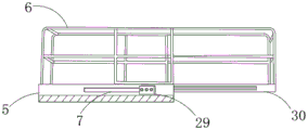
Fig. 1 is a schematic overall structure diagram of the novel platform special for robot assembly lifting.
Fig. 2 is a schematic structural diagram of a lifting platform main body in the novel platform special for robot assembly lifting.
Fig. 3 is a schematic structural diagram of a lifting mechanism in the special platform for robot assembly lifting of the present invention.
Fig. 4 is a schematic structural diagram of a positioning assembly in the special platform for robot assembly lifting of the present invention.
Fig. 5 is a schematic structural diagram of a movable table adjusting assembly in the novel platform special for robot assembly lifting.
Fig. 6 is a schematic structural diagram of a vertical limiting component in the special platform for robot assembly lifting of the invention.
In the figure: 1. a lifting platform main body; 2. connecting blocks; 3. a pneumatic pump; 4. a first movable shaft; 5. a lifting platform; 6. a railing; 7. a chute; 8. a first lifting rod; 9. a push rod; 10. a regulating and controlling box; 11. a component housing; 12. a universal wheel; 13. a connecting shaft; 14. a receiving groove; 15. a movable wheel; 16. mounting grooves; 17. a card slot; 18. a hydraulic pump; 19. a bolt; 20. a second lifting rod; 21. a hydraulic telescopic rod; 22. an engagement assembly; 23. fixing the bottom plate; 24. a slide button; 25. a movable clamping block; 26. rotating the disc; 27. a movable groove; 28. a joining block; 29. a limiting block; 30. a movable table; 31. a movable chute; 32. a limiting mechanism; 33. a connecting rod; 34. and a second movable shaft.
Detailed Description
The technical solutions of the present invention will be clearly and completely described below with reference to the accompanying drawings and the detailed description, but those skilled in the art will understand that the following described embodiments are some, not all, of the embodiments of the present invention, and are only used for illustrating the present invention, and should not be construed as limiting the scope of the present invention. All other embodiments, which can be derived by a person skilled in the art from the embodiments given herein without making any creative effort, shall fall within the protection scope of the present invention. The examples, in which specific conditions are not specified, were conducted under conventional conditions or conditions recommended by the manufacturer. The reagents or instruments used are not indicated by the manufacturer, and are all conventional products available commercially.
In the description of the present invention, it should be noted that the terms "center", "upper", "lower", "left", "right", "vertical", "horizontal", "inner", "outer", etc., indicate orientations or positional relationships based on the orientations or positional relationships shown in the drawings, and are only for convenience of description and simplicity of description, but do not indicate or imply that the device or element being referred to must have a particular orientation, be constructed and operated in a particular orientation, and thus, should not be construed as limiting the present invention. Furthermore, the terms "first," "second," and "third" are used for descriptive purposes only and are not to be construed as indicating or implying relative importance.
In the description of the present invention, it should be noted that, unless otherwise explicitly specified or limited, the terms "mounted," "connected," and "connected" are to be construed broadly, e.g., as meaning either a fixed connection, a removable connection, or an integral connection; can be mechanically or electrically connected; they may be connected directly or indirectly through intervening media, or they may be interconnected between two elements. The specific meanings of the above terms in the present invention can be understood in specific cases to those skilled in the art.
The first embodiment is as follows:
as shown in fig. 1-4, a novel platform special for robot assembly lifting comprises a lifting platform main body 1, wherein a containing groove 14 is formed in the inner side of the lifting platform main body 1, two groups of connecting shafts 13 are movably connected to the inner side of the containing groove 14, a universal wheel 12 is movably connected to one end of the lifting platform main body 1, a mounting groove 16 is formed in the lower end of the lifting platform main body 1, two clamping grooves 17 are formed in the inner side of the mounting groove 16, and a component shell 11 is fixedly connected to the inner side of the mounting groove 16.
One side fixedly connected with regulation and control case 10 of activity wheel 15, the upper end fixedly connected with push rod 9 of regulation and control case 10, the outside swing joint of connecting axle 13 has lifter 20 No. two, the inboard swing joint of lifter 20 No. two has bolt 19, one side swing joint of bolt 19 has lifter 8 No. one, the mutual assembly swing joint of lifter 8, lifter 20 No. two of multiunit, one side fixedly connected with hydraulic pump 18 of lifter 20 No. two.
The inboard swing joint of hydraulic pump 18 has hydraulic telescoping rod 21, and hydraulic telescoping rod 21's one end swing joint has linking up subassembly 22, and the upper end swing joint of lifter 8, No. two lifters 20 has elevating platform 5, and the upper end fixedly connected with railing 6 of elevating platform 5, spout 7 has been seted up in the outside of elevating platform 5, and the inboard sliding connection of elevating platform 5 has movable table 30, and the one end fixedly connected with stopper 29 of movable table 30.
The outside fixedly connected with connecting block 2 of elevating platform main part 1, one side fixedly connected with pneumatic pump 3 of connecting block 2, the inboard swing joint of pneumatic pump 3 has loose axle 4 No. one, the inboard swing joint of loose axle 4 has loose axle 34 No. two, the one end fixedly connected with connecting rod 33 of loose axle 34 No. two, movable spout 31 has been seted up to the inboard of loose axle 4, the inboard sliding connection of movable spout 31 has stop gear 32, with locating component fixed mounting to the inboard of mounting groove 16, go into draw-in groove 17 through slip knob 24 with both sides activity fixture block 25 linkage card and fix.
The inner side of the component shell 11 is movably connected with one end of a movable clamping block 25 through a sliding button 24 and a movable groove 27, the interior of the component shell 11 is movably connected with the upper end of a fixed bottom plate 23 through a rotating disc 26 and a connecting block 28, the lifting table is moved to a position to be operated, the fixed bottom plate 23 is pressed downwards through rotating the rotating disc 26, and the lifting table main body 1 is positioned and fixed to prevent the lifting table main body 1 from moving in the operation process.
Example two:
as shown in fig. 1-3 and 5, a novel platform special for robot assembly lifting comprises a lifting platform main body 1, wherein a containing groove 14 is formed in the inner side of the lifting platform main body 1, two groups of connecting shafts 13 are movably connected to the inner side of the containing groove 14, a universal wheel 12 is movably connected to one end of the lifting platform main body 1, a mounting groove 16 is formed in the lower end of the lifting platform main body 1, two clamping grooves 17 are formed in the inner side of the mounting groove 16, and a component shell 11 is fixedly connected to the inner side of the mounting groove 16.
One side fixedly connected with regulation and control case 10 of activity wheel 15, the upper end fixedly connected with push rod 9 of regulation and control case 10, the outside swing joint of connecting axle 13 has lifter 20 No. two, the inboard swing joint of lifter 20 No. two has bolt 19, one side swing joint of bolt 19 has lifter 8 No. one, the mutual assembly swing joint of lifter 8, lifter 20 No. two of multiunit, one side fixedly connected with hydraulic pump 18 of lifter 20 No. two.
The inboard swing joint of hydraulic pump 18 has hydraulic telescoping rod 21, and hydraulic telescoping rod 21's one end swing joint has linking up subassembly 22, and the upper end swing joint of lifter 8, No. two lifters 20 has elevating platform 5, and the upper end fixedly connected with railing 6 of elevating platform 5, spout 7 has been seted up in the outside of elevating platform 5, and the inboard sliding connection of elevating platform 5 has movable table 30, and the one end fixedly connected with stopper 29 of movable table 30.
The outside fixedly connected with connecting block 2 of elevating platform main part 1, one side fixedly connected with pneumatic pump 3 of connecting block 2, the inboard swing joint of pneumatic pump 3 has loose axle 4 No. one, the inboard swing joint of loose axle 4 has loose axle 34 No. two, the one end fixedly connected with connecting rod 33 of loose axle 34 No. two, movable spout 31 has been seted up to the inboard of loose axle 4, the inboard sliding connection of movable spout 31 has stop gear 32, it fixes to install elevating system's upper end with movable table adjusting part.
The inside of elevating platform 5 passes through the outside sliding connection of spout 7, stopper 29 and activity platform 30, and railing 6 and elevating platform 5 are through welded mode fixed connection between, and the adaptation height that adjusts the elevating platform when using is fixed a position, arrives through activity platform 30 and waits to operate the position and assemble the operation.
Example three:
as shown in fig. 1-3 and 6, a novel platform special for robot assembly lifting comprises a lifting platform main body 1, wherein a containing groove 14 is formed in the inner side of the lifting platform main body 1, two groups of connecting shafts 13 are movably connected to the inner side of the containing groove 14, a universal wheel 12 is movably connected to one end of the lifting platform main body 1, a mounting groove 16 is formed in the lower end of the lifting platform main body 1, two clamping grooves 17 are formed in the inner side of the mounting groove 16, and a component shell 11 is fixedly connected to the inner side of the mounting groove 16.
One side fixedly connected with regulation and control case 10 of activity wheel 15, the upper end fixedly connected with push rod 9 of regulation and control case 10, the outside swing joint of connecting axle 13 has lifter 20 No. two, the inboard swing joint of lifter 20 No. two has bolt 19, one side swing joint of bolt 19 has lifter 8 No. one, the mutual assembly swing joint of lifter 8, lifter 20 No. two of multiunit, one side fixedly connected with hydraulic pump 18 of lifter 20 No. two.
The inboard swing joint of hydraulic pump 18 has hydraulic telescoping rod 21, and hydraulic telescoping rod 21's one end swing joint has linking up subassembly 22, and the upper end swing joint of lifter 8, No. two lifters 20 has elevating platform 5, and the upper end fixedly connected with railing 6 of elevating platform 5, spout 7 has been seted up in the outside of elevating platform 5, and the inboard sliding connection of elevating platform 5 has movable table 30, and the one end fixedly connected with stopper 29 of movable table 30.
The outside fixedly connected with connecting block 2 of elevating platform main part 1, one side fixedly connected with pneumatic pump 3 of connecting block 2, the inboard swing joint of pneumatic pump 3 has loose axle 4 No. one, the inboard swing joint of loose axle 4 has loose axle 34 No. two, the one end fixedly connected with connecting rod 33 of loose axle 34 No. two, movable spout 31 has been seted up to the inboard of loose axle 4 No. two, the inboard sliding connection of movable spout 31 has stop gear 32, install elevating system's one end with perpendicular spacing subassembly, through loose axle 4, No. two loose axles 34 and elevating system linkage go up and down.
The inner side of the pneumatic pump 3 is movably connected with the lower end of the second movable shaft 34 through the first movable shaft 4, the inner sides of the first movable shaft 4 and the second movable shaft 34 are slidably connected with one side of the limiting mechanism 32 through the movable sliding groove 31, the lifting platform is vertically limited, and the lifting platform is prevented from being laterally turned due to deviation in the vertical lifting process.
The working principle is as follows: the invention comprises a lifting platform main body 1, a connecting block 2, a pneumatic pump 3, a first movable shaft 4, a lifting platform 5, a railing 6, a sliding groove 7, a first lifting rod 8, a push rod 9, a regulating and controlling box 10, a component shell 11, a universal wheel 12, a connecting shaft 13, a receiving groove 14, a movable wheel 15, a mounting groove 16, a clamping groove 17, a hydraulic pump 18, a bolt 19, a second lifting rod 20, a hydraulic telescopic rod 21, a linking component 22, a fixed bottom plate 23, a sliding button 24, a movable clamping block 25, a rotating disc 26, a movable groove 27, a linking block 28, a limiting block 29, a movable platform 30, a movable sliding groove 31, a limiting mechanism 32, a connecting rod 33 and a second movable shaft 34, wherein the positioning component can be fixedly mounted on the inner side of the mounting groove 16 before use, the movable clamping blocks 25 on two sides are clamped into the clamping groove 17 in a linkage manner through the sliding button 24 to fix, the lifting platform is moved to a position to be operated, the fixed bottom plate 23 is downwards pressed by rotating the rotating disc 26, the lifting platform main body 1 is positioned and fixed to prevent movement in the operation process, the movable platform adjusting component is installed at the upper end of the lifting structure to be fixed, the adaptive height adjusted by the lifting platform is positioned when the lifting platform is used, the lifting platform reaches the position to be operated through the movable platform 30 to be assembled, the vertical limiting component is installed at one end of the lifting mechanism and is linked with the lifting mechanism through the first movable shaft 4 and the second movable shaft 34 to lift, the lifting platform is vertically limited to prevent the lifting platform from being shifted to cause side turning in the vertical lifting process, the lifting platform base is conveniently fixed by adding the positioning component to prevent accidents in the use process, and the assembly operation can be conveniently carried out by operators at the position of the upper end adjusting platform by adding the movable platform adjusting component, through increasing perpendicular spacing subassembly, can effectively avoid lift platform to take place the skew when going up to rise, fall, take place to turn on one's side when effectively avoiding lift platform to use, whole easy operation is swift, comparatively practical.
It is noted that, herein, relational terms such as first and second (a, b, etc.) and the like may be used solely to distinguish one entity or action from another entity or action without necessarily requiring or implying any actual such relationship or order between such entities or actions. Also, the terms "comprises," "comprising," or any other variation thereof, are intended to cover a non-exclusive inclusion, such that a process, method, article, or apparatus that comprises a list of elements does not include only those elements but may include other elements not expressly listed or inherent to such process, method, article, or apparatus. Without further limitation, an element defined by the phrase "comprising an … …" does not exclude the presence of other identical elements in a process, method, article, or apparatus that comprises the element.
The foregoing shows and describes the general principles and broad features of the present invention and advantages thereof. It will be understood by those skilled in the art that the present invention is not limited to the embodiments described above, which are described in the specification and illustrated only to illustrate the principle of the present invention, but that various changes and modifications may be made therein without departing from the spirit and scope of the present invention, which fall within the scope of the invention as claimed.
Claims (8)
1. The utility model provides a novel robot assembly lift specialized platform, includes elevating platform main part (1), its characterized in that: the inboard of elevating platform main part (1) has been seted up and has been accomodate groove (14), the inboard swing joint who accomodates groove (14) has two sets of connecting axles (13), the one end swing joint of elevating platform main part (1) has universal wheel (12), mounting groove (16) have been seted up to the lower extreme of elevating platform main part (1), two draw-in grooves (17) have been seted up to the inboard of mounting groove (16), inboard fixedly connected with subassembly casing (11) of mounting groove (16).
2. The novel platform special for robot assembly lifting as claimed in claim 1, wherein: activity groove (27) have been seted up in the outside of subassembly casing (11), the inboard sliding connection in activity groove (27) has slide button (24), the inboard fixedly connected with activity fixture block (25) of slide button (24), one side swing joint in activity groove (27) has spinning disk (26), the inside swing joint of subassembly casing (11) has links up piece (28), the lower extreme fixedly connected with PMKD (23) of linking up piece (28), one side swing joint in mounting groove (16) has activity wheel (15).
3. The novel platform special for robot assembly lifting as claimed in claim 2, wherein: one side fixedly connected with regulation and control case (10) of activity wheel (15), upper end fixedly connected with push rod (9) of regulation and control case (10), the outside swing joint of connecting axle (13) has lifter (20) No. two, the inboard swing joint of lifter (20) No. two has bolt (19), one side swing joint of bolt (19) has lifter (8) No. one, a multiunit lifter (8), lifter (20) be assembled swing joint each other, one side fixedly connected with hydraulic pump (18) of lifter (20) No. two.
4. The novel platform special for robot assembly lifting as claimed in claim 3, wherein: the inboard swing joint of hydraulic pump (18) has hydraulic telescoping rod (21), the one end swing joint of hydraulic telescoping rod (21) links up subassembly (22), the upper end swing joint of lifter (8), No. two lifters (20) has elevating platform (5), the upper end fixedly connected with railing (6) of elevating platform (5), spout (7) have been seted up in the outside of elevating platform (5), the inboard sliding connection of elevating platform (5) has movable table (30), the one end fixedly connected with stopper (29) of movable table (30).
5. The novel platform special for robot assembly lifting as claimed in claim 1, wherein: the outside fixedly connected with connecting block (2) of elevating platform main part (1), one side fixedly connected with pneumatic pump (3) of connecting block (2), the inboard swing joint of pneumatic pump (3) has loose axle (4) No. one, the inboard swing joint of loose axle (4) has loose axle (34) No. two, the one end fixedly connected with connecting rod (33) of loose axle (34) No. two, movable chute (31) have been seted up to the inboard of loose axle (34), loose axle (4) No. two, the inboard sliding connection of movable chute (31) has stop gear (32).
6. The novel platform special for robot assembly lifting as claimed in claim 2, wherein: the inboard of subassembly casing (11) is through the one end swing joint of slide button (24), activity groove (27) and activity fixture block (25), the inside of subassembly casing (11) is through the upper end swing joint of spinning disk (26), linking piece (28) and PMKD (23).
7. The novel platform special for robot assembly lifting as claimed in claim 4, wherein: the inner side of the lifting platform (5) is connected with the outer side of the movable platform (30) in a sliding mode through a sliding groove (7) and a limiting block (29), and the railing (6) is fixedly connected with the lifting platform (5) in a welding mode.
8. The novel platform special for robot assembly lifting as claimed in claim 5, wherein: the inboard of pneumatic pump (3) is through the lower extreme swing joint of a loose axle (4) and No. two loose axles (34), the inboard of a loose axle (4), No. two loose axles (34) is through one side sliding connection of activity spout (31) and stop gear (32).
Priority Applications (1)
| Application Number | Priority Date | Filing Date | Title |
|---|---|---|---|
| CN202111561277.8A CN114161381A (en) | 2021-12-17 | 2021-12-17 | Novel special lifting platform for robot assembly |
Applications Claiming Priority (1)
| Application Number | Priority Date | Filing Date | Title |
|---|---|---|---|
| CN202111561277.8A CN114161381A (en) | 2021-12-17 | 2021-12-17 | Novel special lifting platform for robot assembly |
Publications (1)
| Publication Number | Publication Date |
|---|---|
| CN114161381A true CN114161381A (en) | 2022-03-11 |
Family
ID=80487437
Family Applications (1)
| Application Number | Title | Priority Date | Filing Date |
|---|---|---|---|
| CN202111561277.8A Pending CN114161381A (en) | 2021-12-17 | 2021-12-17 | Novel special lifting platform for robot assembly |
Country Status (1)
| Country | Link |
|---|---|
| CN (1) | CN114161381A (en) |
Citations (8)
| Publication number | Priority date | Publication date | Assignee | Title |
|---|---|---|---|---|
| KR20080039329A (en) * | 2007-12-26 | 2008-05-07 | 한성물류운반기계(주) | High place works car |
| KR20140079058A (en) * | 2012-12-18 | 2014-06-26 | 김연한 | High place working vehicles |
| CN207659037U (en) * | 2017-11-12 | 2018-07-27 | 中科盛博建设集团有限公司 | A kind of vertical-type building hoist |
| CN207905157U (en) * | 2018-02-28 | 2018-09-25 | 山东国建工程集团有限公司 | building damping device |
| CN211169765U (en) * | 2019-12-27 | 2020-08-04 | 国网重庆市电力公司合川供电分公司 | Addressing and first-aid repair platform for electricity customers |
| CN212825343U (en) * | 2020-06-29 | 2021-03-30 | 湖北金诚信矿业服务有限公司 | Quick overhaul device convenient to adjust for overhaul of mine engineering machinery apparatus |
| CN213679702U (en) * | 2020-09-17 | 2021-07-13 | 山东泰沃重工有限公司 | Anti-shaking lifting platform |
| CN214243713U (en) * | 2020-11-27 | 2021-09-21 | 无锡商业职业技术学院 | Dedicated jacking equipment of electromechanical installation |
-
2021
- 2021-12-17 CN CN202111561277.8A patent/CN114161381A/en active Pending
Patent Citations (8)
| Publication number | Priority date | Publication date | Assignee | Title |
|---|---|---|---|---|
| KR20080039329A (en) * | 2007-12-26 | 2008-05-07 | 한성물류운반기계(주) | High place works car |
| KR20140079058A (en) * | 2012-12-18 | 2014-06-26 | 김연한 | High place working vehicles |
| CN207659037U (en) * | 2017-11-12 | 2018-07-27 | 中科盛博建设集团有限公司 | A kind of vertical-type building hoist |
| CN207905157U (en) * | 2018-02-28 | 2018-09-25 | 山东国建工程集团有限公司 | building damping device |
| CN211169765U (en) * | 2019-12-27 | 2020-08-04 | 国网重庆市电力公司合川供电分公司 | Addressing and first-aid repair platform for electricity customers |
| CN212825343U (en) * | 2020-06-29 | 2021-03-30 | 湖北金诚信矿业服务有限公司 | Quick overhaul device convenient to adjust for overhaul of mine engineering machinery apparatus |
| CN213679702U (en) * | 2020-09-17 | 2021-07-13 | 山东泰沃重工有限公司 | Anti-shaking lifting platform |
| CN214243713U (en) * | 2020-11-27 | 2021-09-21 | 无锡商业职业技术学院 | Dedicated jacking equipment of electromechanical installation |
Similar Documents
| Publication | Publication Date | Title |
|---|---|---|
| CN108145700A (en) | A kind of composite intelligent captures robot | |
| CN202240367U (en) | Positioner for assembly production line of passenger car bogie | |
| CN105947613A (en) | Automatic turnover machine | |
| CN105150158A (en) | Mutual inductor assembly positioner | |
| CN104495636A (en) | Balanced hoisting device | |
| CN114161381A (en) | Novel special lifting platform for robot assembly | |
| CN110814732B (en) | Automatic frame overturning machine | |
| CN110479889B (en) | Special automation equipment of door welding upset manipulator | |
| CN111573567B (en) | Material lifting and carrying equipment for industrial building construction and working method thereof | |
| CN213502386U (en) | Engine transfer device for vehicle assembly | |
| CN109014915A (en) | A kind of case of transmission overturning assembly device | |
| CN212559156U (en) | Cantilever type top cover conveying trolley system | |
| CN205057908U (en) | Mutual -inductor assembly machine of shifting | |
| CN104942208B (en) | A kind of rotary table for riveting auto parts machinery | |
| CN113845023A (en) | Lifting appliance for lifting and overturning vehicle body and using method thereof | |
| CN112693803A (en) | Have raising and lowering functions transmission device | |
| CN218909003U (en) | Workpiece fixing device | |
| CN109226526A (en) | A kind of molding equipment of refrigerator sheet metal component | |
| CN217394213U (en) | Telescopic boom driving oil cylinder installation machine | |
| CN213356170U (en) | Basket lifting walking device | |
| CN219884995U (en) | Spool intelligent overturning manipulator | |
| CN213202214U (en) | Floating vertical lift | |
| CN217864279U (en) | Transfer trolley for producing ratchet screw jack | |
| CN219730402U (en) | Subassembly lift translation device | |
| CN113860145B (en) | Electric horizontal roll clamp and use method thereof |
Legal Events
| Date | Code | Title | Description |
|---|---|---|---|
| PB01 | Publication | ||
| PB01 | Publication | ||
| SE01 | Entry into force of request for substantive examination | ||
| SE01 | Entry into force of request for substantive examination |