Multi-shaft turning and milling composite numerical control machine tool
Technical Field
The invention relates to the technical field of numerical control machining, in particular to a multi-shaft turning and milling composite numerical control machine tool.
Background
At present, the manufacturing industry in China is in a vigorous development period, and the drilling and milling requirements of various workpieces are very large, so that numerical control drilling and milling machine tools are increasingly widely applied, and the current domestic numerical control drilling and milling machine tools have great market demands. Most of the existing numerical control drilling and milling machine tools produced by domestic enterprises only have one drilling and milling head, so that the working efficiency is low when large-batch processing tasks are carried out, and the labor intensity of operators is high.
When the number of the drilling and milling processing heads is increased, the space structure is required to be increased greatly, the structure is relatively complex, and even if the number of the drilling and milling processing heads is increased, only one processing mode is realized, for example, only a punching function or a tapping or milling function is realized, and a mode of synchronously punching or tapping (or milling contour) cannot be realized at the same time, so that the processing is not flexible, and the processing efficiency is low, so that the improvement is needed.
Disclosure of Invention
The invention aims to provide a multi-axis turning and milling composite numerical control machine tool to solve the problems of inflexible processing and low processing efficiency in the background technology.
In order to achieve the purpose, the invention provides the following technical scheme: the utility model provides a compound digit control machine tool of multiaxis turnning and milling, includes the inside lathe body that takes the controller and is used for placing the processing platform of processing product, is provided with the feed transmission that can make the processing platform move in the X direction and the Y direction of horizontal plane on the lathe body, its characterized in that: still be provided with the Z axle that carries out processing to the product on the processing platform on the lathe body and bore the milling device, the Z axle is bored and is milled the device and include rotatory servo motor of main shaft, two main shaft unit heads and two Z axle feed motors, the Z axle bore the milling device and carry out the up-and-down motion by each main shaft unit head of two Z axle feed motors individual drive in vertical direction, realize the independent adjustment of vertical distance between two main shaft unit heads and the product, and two main shaft unit heads are rotatory by the rotatory servo motor drive of main shaft, install milling cutter or drill bit or screw tap through the screw dismantlement formula in the below of each main shaft unit head.
Preferably, a main shaft support is arranged on the machine tool body, two tapping supports are fixed at the front end of the main shaft support, a tapping drill is fixed on each tapping support, a tapping drilling main shaft and a feeding screw rod are arranged in each tapping drill, a fixing plate is arranged above each tapping drill, a servo auxiliary synchronizing wheel is connected to the upper end of each tapping drilling main shaft after penetrating through the fixing plate, a main shaft rotating servo motor is fixed below the fixing plate, a servo main synchronizing wheel is connected to the output shaft of each main shaft rotating servo motor after penetrating through the fixing plate, two servo auxiliary synchronizing wheels and the servo main synchronizing wheel are in synchronous belt transmission, the upper end of each feeding screw rod is connected with a Z-axis feeding motor, a sliding sleeve sleeved outside the tapping drilling main shaft is connected to the feeding screw rod in a sliding mode, and the sliding sleeve can move up and down along the tapping drilling main shaft, the lower portion of the sliding sleeve is connected with the spindle power head in a rotating mode, the tapping drilling spindle is further connected with the spindle power head in a transmission mode, the Z-axis feeding motor drives the sliding sleeve to move up and down, and the tapping drilling spindle drives the spindle power head to rotate.
Preferably, for convenience of operation, the feeding transmission device includes a Y-axis servo motor and an X-axis servo motor, the Y-axis servo motor is fixed on the machine tool body and located below the spindle support, a Y-axis guide rail extending along the Y-axis direction is arranged on the machine tool body, a bottom plate is connected on the two Y-axis guide rails in a sliding manner, a second slider connected on the Y-axis guide rail in a sliding manner is arranged at the bottom of the bottom plate, the output of the Y-axis servo motor is connected with a first lead screw, a first lead screw nut is connected on the first lead screw in a threaded manner, a first nut seat sleeved outside the first lead screw is fixedly connected on the first lead screw nut, the first lead screw seat is connected with the bottom plate, the output of the X-axis servo motor is connected with a second lead screw, a second lead screw nut is connected on the second lead screw in a threaded manner, a second nut seat sleeved outside the second lead screw is fixedly connected on the second lead screw nut, the machining table is fixed above the machining seat, two X-axis guide rails are arranged at the bottom of the machining seat, more than one first sliding block is connected to each X-axis guide rail in a sliding mode, the first sliding blocks are fixed to the upper surface of the bottom plate, the machining table is installed on the machining seat, the X-axis servo motor is fixed to the side edge of the machining seat, a motor protective sleeve is sleeved outside the X-axis servo motor, and a foldable organ protective cover which covers the exposed Y-axis guide rail and the first lead screw is arranged between the spindle support and the bottom plate.
Preferably, the cooling effect is improved, tool cooling pipes with openings facing the lower part of the main shaft power head are further arranged on two sides of the main shaft support, and the tool cooling pipes are connected with cooling punches.
Preferably, a liquid discharge port is provided at a side of the machining seat in order to rapidly discharge the coolant and the scraps.
Preferably, the processing base is provided with a processing hood for blocking the periphery of the processing table, and the front end of the processing hood is provided with a openable cover door.
Preferably, the safety is improved, and the two tapping supports are sleeved with one mounting cover.
Preferably, for the convenience of display, a display screen support is arranged on the side edge of the main shaft support, and an inch display screen is arranged on the display screen support.
In order to improve the safety, a safety induction signal lamp is arranged on the display screen.
In order to collect waste material and coolant liquid fast, be provided with the waste liquid collection shallow with the leakage fluid dram intercommunication at the side of lathe body, the below of waste liquid collection shallow is provided with the cooling oil pump that is used for adding the cooling tool man-hour, the output of cooling oil pump with the cutter cooling tube intercommunication.
Compared with the prior art, the invention has the following beneficial effects: this structure setting will have the mode of a quick-witted one control, carry out the mode of a tractor serves many controls, the during operation is rotated by two main shaft unit heads of the rotatory servo motor synchronous drive of main shaft to by two Z axle feed motor individual drive main shaft unit heads up-and-down motion in vertical direction, the later stage only need connect different milling cutter or drill bit or screw tap respectively with two main shaft unit heads, finally realize that an equipment can punch the processing simultaneously or attack tooth or single operation simultaneously to the product: the tapping operation process of one punching or different sizes of tapping enables the processing efficiency of the whole equipment to be higher and the application range to be wider.
Drawings
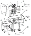
Fig. 1 is a schematic structural view of a multi-axis turning and milling composite numerical control machine tool in embodiment 1;
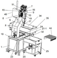
fig. 2 is a schematic structural diagram of the installation cover, the synchronous belt, the motor protection cover and the cover door of the multi-axis turning and milling composite numerical control machine tool in embodiment 1 when no other components are separated;
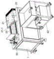
FIG. 3 is a schematic view of a back side structure of the multi-axis turning and milling composite numerical control machine tool of embodiment 1 without an installation mounting cover;
FIG. 4 is a schematic view of the accordion guard of FIG. 3 shown separated from the rest of the housing;
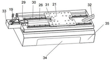
FIG. 5 is a schematic bottom view of the machining seat connected to the base plate;
FIG. 6 is a schematic view of the structure of the base plate of FIG. 5, shown separated from other components;
FIG. 7 is a schematic structural diagram of the base plate and the machine tool body;
fig. 8 is a schematic view of the structure of the bottom plate of fig. 7 when separated from other components.
In the figure: the machine tool comprises a machine tool body 1, a processing table 2, a feeding transmission device 3, a Z-axis drilling and milling device 4, a main shaft rotating servo motor 5, a main shaft power head 6, a Z-axis feeding motor 7, a main shaft support 8, a tapping support 9, a tapping drill 10, a tapping drilling main shaft 11, a feeding screw rod 12, a fixing plate 13, a servo auxiliary synchronizing wheel 14, a servo main synchronizing wheel 15, a synchronous belt 16, a sliding sleeve 17, a Y-axis servo motor 18, an X-axis servo motor 19, a Y-axis guide rail 20, a bottom plate 21, a bottom plate shield 21-1, a second sliding block 22, a first screw rod 23, a first screw rod nut 25, a first nut seat 24, a second screw rod 26, a second screw rod nut 27, a second nut seat 28, a processing seat 29, an X-axis guide rail 30, a first sliding block 31, a liquid discharge port 32, a motor protective cover 33, a cover door 34, a processing protective cover 35, a mounting cover punch 36, a cutter cooling pipe 37, a cooling pipe 38, a machining tool head and a machining tool, Display screen support 39, display screen 40, safety induction signal lamp 41, waste liquid collection cart 42, cooling oil pump 43, collapsible organ protection casing 44.
Detailed Description
The technical solutions in the embodiments of the present invention will be clearly and completely described below with reference to the drawings in the embodiments of the present invention, and it is obvious that the described embodiments are only a part of the embodiments of the present invention, and not all of the embodiments. All other embodiments, which can be derived by a person skilled in the art from the embodiments given herein without making any creative effort, shall fall within the protection scope of the present invention.
In the description of the present invention, it should be noted that the terms "upper", "lower", "inner", "outer", "front", "rear", "both ends", "one end", "the other end", and the like indicate orientations or positional relationships based on those shown in the drawings, and are only for convenience of description and simplicity of description, but do not indicate or imply that the referred device or element must have a specific orientation, be constructed in a specific orientation, and be operated, and thus, should not be construed as limiting the present invention. Furthermore, the terms "first" and "second" are used for descriptive purposes only and are not to be construed as indicating or implying relative importance.
In the description of the present invention, it is to be noted that, unless otherwise explicitly specified or limited, the terms "mounted," "disposed," "connected," and the like are to be construed broadly, such as "connected," which may be fixedly connected, detachably connected, or integrally connected; can be mechanically or electrically connected; they may be connected directly or indirectly through intervening media, or they may be interconnected between two elements. The specific meanings of the above terms in the present invention can be understood in specific cases to those skilled in the art.
Example 1:
referring to fig. 1-8, an embodiment of the present invention is shown: the utility model provides a compound digit control machine tool of multiaxis turnning and milling, includes that the inside lathe body 1 that takes the controller and be used for placing the processing platform 2 of processing product are provided with on lathe body 1 and can make processing platform 2 at the X direction of horizontal plane and the feeding transmission 3 of Y direction motion, its characterized in that: still be provided with the Z axle that carries out processing to the product on the processing platform 2 on the lathe body 1 and bore milling device 4, the Z axle bores milling device 4 and includes rotatory servo motor 5 of main shaft, two main shaft unit heads 6 and two Z axle feed motors 7, Z axle bore milling device 4 by two Z axle feed motors 7 individual drive each main shaft unit head 6 up-and-down motion in vertical direction, realize the independent adjustment of vertical distance between two main shaft unit heads 6 and the product, and two main shaft unit heads 6 are rotatory by the rotatory servo motor 5 drive of main shaft, install milling cutter or drill bit or screw tap through the screw dismantlement formula in the below of each main shaft unit head 6.
This structure setting is with the mode of current a quick-witted one control, carry out the mode of a tractor serves many controls, in operation, it is rotatory to drive two main shaft unit heads 6 by the rotatory servo motor 5 synchronization of main shaft, and by two Z axle feed motors 7 independent drive main shaft unit heads 6 up-and-down motion in vertical direction, the later stage only need connect different milling cutter or drill bit or screw tap respectively with two main shaft unit heads 6, finally realize that an equipment can punch the processing simultaneously or attack tooth or single operation simultaneously to the product: the tapping operation process of one punching or different sizes of tapping enables the processing efficiency of the whole equipment to be higher and the application range to be wider.
Preferably, a main shaft support 8 is arranged on the machine tool body 1, two tapping supports 9 are fixed at the front end of the main shaft support 8, a tapping drill 10 is fixed on each tapping support 9, a tapping drilling main shaft 11 and a feeding screw rod 12 are arranged in each tapping drill 10, a fixing plate 13 is arranged above each tapping drill 10, a servo auxiliary synchronizing wheel 14 is connected to the upper end of each tapping drilling main shaft 11 after penetrating through the fixing plate 13, a main shaft rotating servo motor 5 is fixed below the fixing plate 13, a servo main synchronizing wheel 15 is connected to the output shaft of the main shaft rotating servo motor 5 after penetrating through the fixing plate 13, two servo auxiliary synchronizing wheels 14 and the servo main synchronizing wheel 15 are driven by a synchronous belt 16, the upper end of the feeding screw rod 12 is connected with a Z-axis feeding motor 7, and a sliding sleeve 17 sleeved outside the tapping drilling main shaft 11 is slidably connected to the feeding screw rod 12, sliding sleeve 17 can reciprocate along attacking tooth drilling main shaft 11, sliding sleeve 17 below with main shaft unit head 6 rotate and connect, attack tooth drilling main shaft 11 still with main shaft unit head 6 transmission connect, the drive of Z axle feed motor 7 sliding sleeve 17 reciprocates, attack tooth drilling main shaft 11 drive main shaft unit head 6 rotatory, just when sliding sleeve 17 reciprocates, can not influence main shaft unit head 6 rotatory.
This structure can realize punching simultaneously the processing or simultaneously attack tooth or single operation to the product, and one punches one and attacks tooth or carry out the not unidimensional operation process of attacking. During operation, the main shaft unit head 6 of left and right sides can connect different processing heads respectively, milling cutter or drill bit or screw tap, when the product that punches is connected to left main shaft unit head 6, only need to drive feed lead screw 12 rotatory through driving left Z axle feed motor 7, finally drive left sliding sleeve 17 and reciprocate, drive main shaft unit head 6 of below and reciprocate and realize opening, when the product that needs to the right side carries out the tapping, only need to drive two main shaft unit heads 6 synchronous rotations through the work of drive main shaft rotation servo motor 5, and before this because left cutter need not to process the product, consequently can drive sliding sleeve 17 earlier and carry out the rebound, although two cutters are in synchronous rotation, and because the product of left cutter can't be close to the below, consequently, processing is not influenced. The applicant should note that, when the sliding sleeve 17 moves up and down, the specific structure that does not affect the rotation of the spindle power head 6 belongs to the conventional technology in the art, and therefore, will not be described in detail.
Preferably, for convenience of operation, the feed transmission device 3 includes a Y-axis servo motor 18 and an X-axis servo motor 19, the Y-axis servo motor 18 is fixed on the machine tool body 1 and located below the spindle support 8, a Y-axis guide rail 20 extending along the Y-axis direction is provided on the machine tool body 1, a bottom plate 21 is slidably connected on the two Y-axis guide rails 20, a second slider 22 slidably connected on the Y-axis guide rail 20 is provided at the bottom of the bottom plate 21, a first lead screw 23 is connected to an output of the Y-axis servo motor 18, a first lead screw nut 25 is threadedly connected on the first lead screw 23, a first nut seat 24 sleeved outside the first lead screw 23 is fixedly connected on the first lead screw nut 25, the first lead screw nut 25 seat is connected with the bottom plate 21, a second lead screw 26 is connected to an output of the X-axis servo motor 19, a second screw nut 27 is connected to the second screw rod 26 through a screw thread, a second nut seat 28 sleeved outside the second screw rod 26 is fixedly connected to the second screw nut 27, a processing seat 29 is fixed to the second nut seat 28, the processing table 2 is fixed above the processing seat 29, two X-axis guide rails 30 are arranged at the bottom of the processing seat 29, more than one first sliding block 31 is slidably connected to each X-axis guide rail 30, the first sliding block 31 is fixed to the upper surface of the bottom plate 21, the processing table 2 is installed on the processing seat 29, the X-axis servo motor 19 is fixed to the side edge of the processing seat 29, a motor protective cover 33 is sleeved outside the X-axis servo motor 19, and a foldable organ protective cover 44 which covers the exposed Y-axis guide rail 20 and the first screw rod 23 is arranged between the spindle support 8 and the bottom plate 21, a soleplate shield 21-1 is arranged around the soleplate 21.
The accordion guard 44 is located between the floor guard 21-1 and the Y-axis rail 20.
When the X-axis servo motor 19 works to drive the second lead screw 26 to rotate, the second lead screw nut 27 is synchronously driven to move on the second lead screw 26, the machining seat 29 moves along the X-axis direction under the matching of the first sliding block 31 and the X-axis guide rail 30, and finally the position of the workbench 2 can be adjusted by the movement of the X-axis direction and the Y-axis direction of the machining seat 29.
Preferably, in order to quickly remove the coolant and the scraps, a drain port 32 is provided at a side of the machining base 29, and the drilled or milled chips can be discharged from the drain port 32 together with the coolant by providing the drain port 32.
As preferred, improve the security, be provided with on processing seat 29 and be used for the processing protection casing 35 of blocking around processing platform 2, the front end of processing protection casing 35 is provided with the lid door 34 that can open, can avoid piece or coolant liquid to fly in disorder through setting up processing protection casing 35, conveniently collects coolant liquid and product piece, sets up lid door 34 simultaneously and realizes opening the door fast, clears up inside piece and coolant liquid.
Preferably, the safety is improved by providing a mounting cover 36, which is sleeved over the two tapping brackets 9, and by providing a mounting cover 36.
Preferably, a tool cooling pipe 37 having an opening facing downward of the spindle head 6 is further provided on both sides of the spindle holder 8 to enhance the cooling effect, a cooling punch 38 is connected to the tool cooling pipe 37, and the tool cooling pipe 37 is provided to cool the product while machining.
Preferably, for convenience of display, a display screen support 39 is arranged on the side of the spindle support 8, a 10-inch display screen 40 is arranged on the display screen support 39, and the display screen 40 can display the working state of the equipment.
In order to improve the safety, a safety induction signal lamp 41 is arranged on the display screen 40, and the safety induction signal lamp 41 is arranged to light up when a product is processed to remind safety.
In order to collect waste material and coolant liquid fast, be provided with the waste liquid collection shallow 42 that communicates with leakage fluid dram 32 at the side of lathe body 1, the below of waste liquid collection shallow 42 is provided with the cooling oil pump 43 that is used for adding the cooling tool man-hour, the output of cooling oil pump 43 with cutter cooling tube 37 communicate, collect shallow 42 through the side that sets up waste liquid at lathe body 1 and realize collecting coolant liquid and piece fast to utilize cooling oil pump 43 to carry out the coolant liquid fast to cutter cooling tube 37.
It will be evident to those skilled in the art that the invention is not limited to the details of the foregoing illustrative embodiments, and that the present invention may be embodied in other specific forms without departing from the spirit or essential attributes thereof. The present embodiments are therefore to be considered in all respects as illustrative and not restrictive, the scope of the invention being indicated by the appended claims rather than by the foregoing description, and all changes which come within the meaning and range of equivalency of the claims are therefore intended to be embraced therein. Any reference sign in a claim should not be construed as limiting the claim concerned.