CN1140887A - Thermistor apparatus and manufacturing method thereof - Google Patents

Thermistor apparatus and manufacturing method thereof Download PDF

Info

Publication number
CN1140887A
CN1140887A CN96106036A CN96106036A CN1140887A CN 1140887 A CN1140887 A CN 1140887A CN 96106036 A CN96106036 A CN 96106036A CN 96106036 A CN96106036 A CN 96106036A CN 1140887 A CN1140887 A CN 1140887A
Authority
CN
China
Prior art keywords
thermal
resistance
sensitive electric
electric resistance
devices
Prior art date
Legal status (The legal status is an assumption and is not a legal conclusion. Google has not performed a legal analysis and makes no representation as to the accuracy of the status listed.)
Granted
Application number
CN96106036A
Other languages
Chinese (zh)
Other versions
CN1084519C (en
Inventor
胜木隆与
鹿间隆
Current Assignee (The listed assignees may be inaccurate. Google has not performed a legal analysis and makes no representation or warranty as to the accuracy of the list.)
Murata Manufacturing Co Ltd
Original Assignee
Murata Manufacturing Co Ltd
Priority date (The priority date is an assumption and is not a legal conclusion. Google has not performed a legal analysis and makes no representation as to the accuracy of the date listed.)
Filing date
Publication date
Application filed by Murata Manufacturing Co Ltd filed Critical Murata Manufacturing Co Ltd
Publication of CN1140887A publication Critical patent/CN1140887A/en
Application granted granted Critical
Publication of CN1084519C publication Critical patent/CN1084519C/en
Anticipated expiration legal-status Critical
Expired - Lifetime legal-status Critical Current

Links

Images

Classifications

    • HELECTRICITY
    • H01ELECTRIC ELEMENTS
    • H01CRESISTORS
    • H01C7/00Non-adjustable resistors formed as one or more layers or coatings; Non-adjustable resistors made from powdered conducting material or powdered semi-conducting material with or without insulating material
    • HELECTRICITY
    • H01ELECTRIC ELEMENTS
    • H01CRESISTORS
    • H01C17/00Apparatus or processes specially adapted for manufacturing resistors
    • H01C17/22Apparatus or processes specially adapted for manufacturing resistors adapted for trimming
    • H01C17/24Apparatus or processes specially adapted for manufacturing resistors adapted for trimming by removing or adding resistive material
    • H01C17/242Apparatus or processes specially adapted for manufacturing resistors adapted for trimming by removing or adding resistive material by laser
    • HELECTRICITY
    • H01ELECTRIC ELEMENTS
    • H01CRESISTORS
    • H01C1/00Details
    • H01C1/14Terminals or tapping points or electrodes specially adapted for resistors; Arrangements of terminals or tapping points or electrodes on resistors
    • H01C1/1406Terminals or electrodes formed on resistive elements having positive temperature coefficient
    • HELECTRICITY
    • H01ELECTRIC ELEMENTS
    • H01CRESISTORS
    • H01C7/00Non-adjustable resistors formed as one or more layers or coatings; Non-adjustable resistors made from powdered conducting material or powdered semi-conducting material with or without insulating material
    • H01C7/02Non-adjustable resistors formed as one or more layers or coatings; Non-adjustable resistors made from powdered conducting material or powdered semi-conducting material with or without insulating material having positive temperature coefficient
    • YGENERAL TAGGING OF NEW TECHNOLOGICAL DEVELOPMENTS; GENERAL TAGGING OF CROSS-SECTIONAL TECHNOLOGIES SPANNING OVER SEVERAL SECTIONS OF THE IPC; TECHNICAL SUBJECTS COVERED BY FORMER USPC CROSS-REFERENCE ART COLLECTIONS [XRACs] AND DIGESTS
    • Y10TECHNICAL SUBJECTS COVERED BY FORMER USPC
    • Y10TTECHNICAL SUBJECTS COVERED BY FORMER US CLASSIFICATION
    • Y10T29/00Metal working
    • Y10T29/49Method of mechanical manufacture
    • Y10T29/49002Electrical device making
    • Y10T29/49082Resistor making
    • Y10T29/49085Thermally variable

Landscapes

  • Engineering & Computer Science (AREA)
  • Microelectronics & Electronic Packaging (AREA)
  • Physics & Mathematics (AREA)
  • Electromagnetism (AREA)
  • Optics & Photonics (AREA)
  • Plasma & Fusion (AREA)
  • Manufacturing & Machinery (AREA)
  • Ceramic Engineering (AREA)
  • Thermistors And Varistors (AREA)
  • Apparatuses And Processes For Manufacturing Resistors (AREA)

Abstract

A positive-characteristics thermistor apparatus has an insulating case, positive-characteristics thermistor devices, planar terminals, and spring terminals. Whichever thermistor device has a lower resistance of the two thermistor devices is trimmed to have a higher resistance which is near the resistance of the other thermistor device such that the two thermistor devices have substantially the same resistance(for example, within a difference of +/-1 OMEGA ). In other words, a part of an electrode of the thermistor device having a lower resistance is removed with a laser beam.

Description

Thermistor apparatus and manufacture method thereof
The present invention relates to thermistor apparatus, relate to or rather a kind of be used to protect communication equipment for example telephone exchange avoid the overcurrent protection thermistor apparatus and the manufacture method thereof of overcurrent infringement.
Overcurrent protection is known with the thermistor apparatus of positive temperature characterisitic.This device has the thermal-sensitive electric resistance device that has two positive temperature characterisitics in the shell; so that protection communication equipment telephone exchange for example, make it avoid the infringement of the overcurrent that causes by communication line and with lightning surge voltage that the circuit that is connected of power circuit and so on is invaded.Preferably make two resistance differences between the positive temperature characteristic thermistor device level off to 0.This be because communication equipment for example in the telecommunication circuit in the telephone exchange need send and the receiving circuit circuit between keep resistors match.
In the positive temperature characteristic thermistor device of routine,, need cumbersome operation in order to make two resistance differences between positive temperature characteristic thermistor device near 0.Among a large amount of positive temperature characteristic thermistor devices, need to select and make up two operations with two positive temperature characteristic thermistor devices of basic identical resistance.If create conditions difference is arranged slightly, will make positive temperature characteristic thermistor device resistance that very big difference is arranged.
Can consider a kind of like this method, according to resistance positive temperature characteristic thermistor device be pressed group categories, and will make up at the resistance in a certain group.Yet, if the resistance of each in two positive temperature characteristic thermistor devices of different time measurements, because the variation of ambient temperature or changed writing time during each the measurement because resistance measuring instrument is aging.Measurement data possibility inaccuracy, therefore, it is big that the resistance difference between the thermal-sensitive electric resistance device of two combinations becomes.In the worst case, can not maintain the resistors match that transmits and receives between the circuit-line.
It is also conceivable that another kind of method, measure the resistance of each positive temperature characteristic thermistor device, too low-resistance device is carried out trim have higher resistance, make all thermal-sensitive electric resistance devices have the resistance of regulation.If before they were by trim, the resistance at the thermal-sensitive electric resistance device of two combinations of different time measurements for above-mentioned reasons, may make the measurement data inaccuracy, causes the resistance difference inaccuracy between two thermal-sensitive electric resistance devices that obtained by this measurement data.Thereby, can not accurately carry out trim, it is big that the resistance difference between two thermal-sensitive electric resistance devices becomes.
Therefore, an object of the present invention is to provide a kind of thermistor apparatus that is easy to make, two thermal-sensitive electric resistance devices of wherein inserting have very little resistance difference, and the manufacture method that this device is provided.
According to an aspect of the present invention, as described in the claim 1, promptly comprise: an insulation shell by the thermistor apparatus that provides; Be contained in two thermal-sensitive electric resistance devices in the insulation shell; And two pairs of termination cases that are used for two thermal-sensitive electric resistance devices of difference layer folder, wherein the device with less resistive in two kinds of thermal-sensitive electric resistance devices is had higher resistance by trim, basically identical with the resistance of another device in two thermal-sensitive electric resistance devices with high electrical resistance, realize above-mentioned purpose with this.
According to as realize above-mentioned purpose in the another aspect of the present invention described in the claim 2, promptly by the manufacture method of such a kind of thermistor apparatus is provided, the step that this method comprises is: prepare an insulation shell, two thermal-sensitive electric resistance devices are contained in the insulation shell, and prepare two pairs of termination cases that are used for two thermal-sensitive electric resistance devices of difference layer folder; Measure the resistance of two thermal-sensitive electric resistance devices; And a less device of resistance makes it to have higher resistance in two thermal-sensitive electric resistance devices of trim, and this high electrical resistance is basically with to have the resistance of another device of high electrical resistance identical in two thermal-sensitive electric resistance devices.
Realize above-mentioned purpose according to described another aspect of the present invention of claim 3, promptly by the manufacture method of thermistor apparatus is provided, the step that this method comprises is: prepare an insulation shell, two thermal-sensitive electric resistance devices that are contained in the insulation shell, and two pairs of termination cases that are used for two thermal-sensitive electric resistance devices of difference layer folder; Basically measure the resistance of two thermal-sensitive electric resistance devices simultaneously; And have a more low-resistance device in two thermal-sensitive electric resistance devices of trim and make it to have higher resistance, this high electrical resistance is basically with to have the resistance of another device of high electrical resistance identical in two thermal-sensitive electric resistance devices.
Realize above-mentioned purpose according to described another aspect of the present invention of claim 4, promptly by a kind of manufacture method of the thermistor apparatus according to claim 3 is provided, but wherein under such condition, make: two thermal-sensitive electric resistance devices are contained in the insulation shell, basically measure the resistance of two thermal-sensitive electric resistance devices simultaneously, and making it to have higher resistance to having a more low-resistance device trim in two thermal-sensitive electric resistance devices, this higher resistance is basically with to have the resistance of another device of high electrical resistance identical in two thermal-sensitive electric resistance devices.
Another aspect of the present invention according to claim 5, realize above-mentioned purpose, promptly by the manufacture method according to the thermistor apparatus of claim 3 is provided, but wherein under such condition, wherein two thermal-sensitive electric resistance devices are contained in the insulation shell, basically measure the resistance of two thermal-sensitive electric resistance devices simultaneously, and utilize the high energy beam of the perforate incident of a process insulation shell to carry out trim to having a more low-resistance device in two thermal-sensitive electric resistance devices, make it to have higher resistance, this higher resistance is basically with to have the resistance of another device of high electrical resistance identical in two thermal-sensitive electric resistance devices.
In according to the thermistor apparatus of claim 1 and manufacture method, only carry out trim and another thermal-sensitive electric resistance device is not needed to carry out trim one in two thermal-sensitive electric resistance devices according to the thermistor apparatus of claim 2.Therefore, compare with the thermistor apparatus of routine, the trim workload reduces by half.
In method according to the manufacturing thermal-sensitive electric resistance device of claim 3, almost measure the resistance of two thermal-sensitive electric resistance devices simultaneously, thereby this measurement may be subjected to hardly owing to cause the adverse effect that writing time, variation produced owing to variation of ambient temperature and because resistance measuring instrument wears out when measuring resistance.Therefore, accurately measured the resistance difference between two thermal-sensitive electric resistance devices, and carried out accurate trim having more low-resistance thermal-sensitive electric resistance device.
In manufacture method according to the thermal-sensitive electric resistance device of claim 4, because trim and measuring resistance are simultaneously basic and carry out under a kind of like this condition, promptly wherein two thermal-sensitive electric resistance devices are contained in the same housing, assemble swimmingly, have only seldom chance to imitate and crack on the resistance device or cracked, so prevented resistance variations in heat.
In the manufacture method according to the thermal-sensitive electric resistance device of claim 5, owing to use high energy beam when trim, exterior materials almost can not enter in the shell, has improved the reliability of thermal-sensitive electric resistance device.
Therefore, obtained a kind of thermistor apparatus that is easy to make, it has only very little resistance difference in the middle of two built-in thermal-sensitive electric resistance devices.
Fig. 1 is the front elevation of expression according to the partly cut-away of first embodiment of thermistor apparatus of the present invention and manufacture method thereof.
Fig. 2 is the perspective view of a device in two thermal-sensitive electric resistance devices that are used in the thermistor apparatus shown in Fig. 1.
Fig. 3 is the perspective view of another device in two thermal-sensitive electric resistance devices that are used in the thermistor apparatus shown in Fig. 1.
Fig. 4 is the plane graph of expression according to second embodiment of thermistor apparatus of the present invention and manufacture method thereof.
Fig. 5 is the schematic partial sectional view of being got along the line V-V among Fig. 4.
Fig. 6 is the plane graph of the step of manufacturing of the thermistor apparatus in the presentation graphs 4.
Fig. 7 is the schematic partial sectional view that the step of manufacturing of part shown in Figure 6 is followed in expression.
Fig. 8 is a schematic partial sectional view of following the step of manufacturing of part shown in Figure 6.
Fig. 9 is the perspective view that is used for according to the thermal-sensitive electric resistance device of the thermistor apparatus of another embodiment.
Figure 10 is used for the perspective view of the thermal-sensitive electric resistance device of the thermistor apparatus of an embodiment again.
Figure 11 is used for the perspective view of the thermal-sensitive electric resistance device of the thermistor apparatus of an embodiment again.
Figure 12 is used for the perspective view of the thermal-sensitive electric resistance device of the thermistor apparatus of an embodiment again.
Below with reference to each accompanying drawing introduction each preferred embodiment according to thermistor apparatus of the present invention and manufacture method thereof.
First embodiment
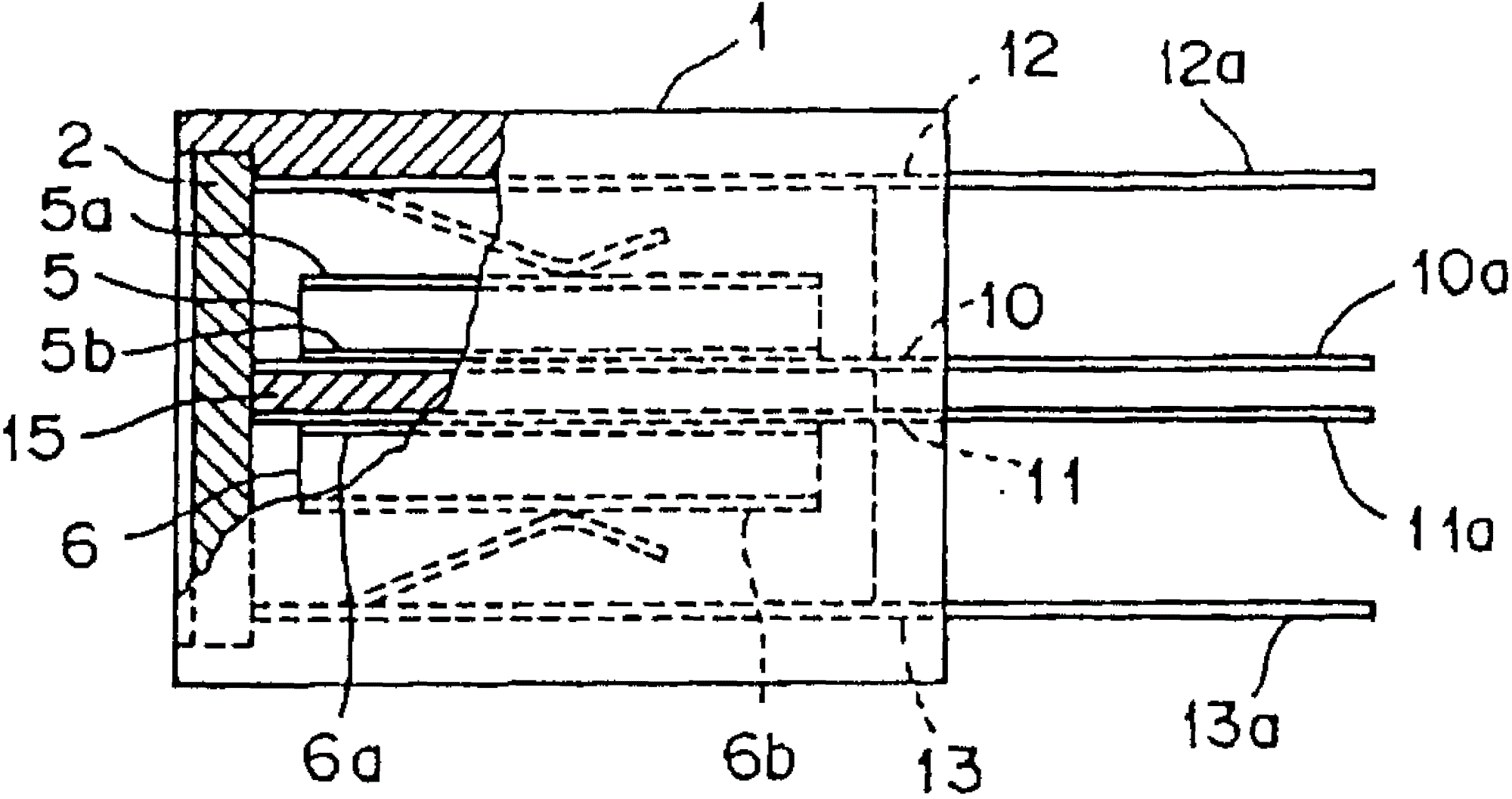
Positive temperature characteristic thermistor device shown in Figure 1 comprises: insulation shell 1,2, two positive temperature characteristic thermistor devices 5 of lid and 6, two dull and stereotyped termination cases 10 and 11, two elastic tip fittings 12 and 13, and insulation dull and stereotyped 15.
Insulation shell 1 STH place leftward is close with covering 2 envelopes.The material that is applicable to insulation shell 1 and lid 2 comprises for example phenol (phenol) and thermoplastic resin polyphenylene sulfide (polyphenylene sulfide) for example of thermosetting resin.
Positive temperature characteristic thermistor device 5 and 6 is rounded, shown in Fig. 2 and 3, by pottery BaTiO for example 3Make.Thermal-sensitive electric resistance device 5 and 6 has electrode 5a, 5b, 6a and 6b on plane, front and back separately.A device that has less resistive in two thermal-sensitive electric resistance devices is carried out trim, make it to have high electrical resistance, this high electrical resistance is bordering on the resistance of other device, makes two thermal-sensitive electric resistance devices have essentially identical resistance (for example, difference is within ± 1 Ω).In first embodiment, utilize laser to carry out trim, remove the part of the electrode 6a of thermal-sensitive electric resistance device 6.
Insulation dull and stereotyped 15 is made by a kind of material with thermal conductive resin, for example constitutes with insulation shell 1 is whole.
Dull and stereotyped termination case 10 and 11 is configured in insulation dull and stereotyped 15 and thermal-sensitive electric resistance device 5 respectively, and between insulation dull and stereotyped 15 and the thermal-sensitive electric resistance device 6, and the electrode 5b of wall surface of contact insulation dull and stereotyped 15 and thermal-sensitive electric resistance device 5, and another wall surface of insulation dull and stereotyped 15 and the electrode 6a of thermal-sensitive electric resistance device 6.Dull and stereotyped termination case 10 and 11 both an end 10a separately and 11a by stretching out on the right side in the housing 1.
Elastic tip fitting 12 and 13 is configured in respectively between housing 1 and the thermal-sensitive electric resistance device 5, and between housing 1 and the thermistor 6, and contact the inner surface of housing 1 and the electrode 5a of thermal-sensitive electric resistance device 5 respectively, and the electrode 6b of another inner surface of housing 1 and thermal-sensitive electric resistance device 6.Elastic tip fitting 12 and 13 both an end 12a separately and 13a are stretched out by housing 1 right-hand member.
Two thermal-sensitive electric resistance devices 5 and 6 utilize termination case 12 and 13 to utilize pressure fixing along thickness direction in the housings 1 by lid 2 sealings, simultaneously their layer dull and stereotyped termination cases 10 of folder and 11 and insulation dull and stereotyped 15.Thermal-sensitive electric resistance device 5 and 6 utilizes insulation dull and stereotyped 15 to make and is electrically insulated from each other.Thermal-sensitive electric resistance device 5 and 6 forms hot link closely (coupling) each other through insulation dull and stereotyped 15 and dull and stereotyped termination case 10 and 11.
To introduce the method for resistance difference between two the positive temperature characteristic thermistor devices 5 and 6 that are used for being reduced in positive temperature characteristic thermistor device below in detail with said structure.
In a plurality of positive temperature characteristic thermistor device of preparing, select two positive temperature characteristic thermistor devices 5 and 6, utilize a resistance measuring instrument to measure their resistance.Preferably almost measure two thermal-sensitive electric resistance devices 5 being contained in the same housing and 6 resistance simultaneously.So just avoided because aging the making that variation of ambient temperature reaches owing to resistance measuring instrument when resistance measurement changes the adverse effect that causes writing time, therefore can accurately measure the resistance difference between two thermal-sensitive electric resistance devices 5 and 6, so that in process thereafter, carry out accurate trim.
Measured accurate resistance data is transported to a calculation processing apparatus and calculates the electrode area that will be removed by a device that has less resistive in two thermal-sensitive electric resistance devices (being thermal-sensitive electric resistance device 6 in first embodiment) by two thermal-sensitive electric resistance devices 5 and 6 s' resistance difference.According to the electrode area that will remove, send a drive signal to a laser balancing device then by calculation processing apparatus.Laser balancing device emission of lasering beam is so that trim has more low-resistance thermal-sensitive electric resistance device 6.In other words, remove the part of electrode 6a and the area that the entire electrode area is deducted appointment.The thermal-sensitive electric resistance device 6 that has been partly removed electrode 6a has the high electrical resistance than before this, and this resistance and another thermal-sensitive electric resistance device 5 are basic identical.Can carry out twice or trim more frequently.If need another time trim, measure the resistance of thermal-sensitive electric resistance device once more and carry out trim.
Therefore obtain having two positive temperature characteristic thermistor devices 5 and 6 of small resistor difference very.Owing to only the temperature-sensitive device 6 with less resistive is carried out trim, to compare with the conventional method that two thermal-sensitive electric resistance devices are carried out trim, the trim workload reduces by half.
Second embodiment (Fig. 4 is to Fig. 8)
Shown in Figure 4 and 5, positive temperature characteristic thermistor device comprises: the termination case 30 and 31 of insulation shell 21, two positive temperature characteristic thermistor devices 25 and 26, two projectioies, and two elastic tip fittings 32 and 33.
Insulation shell 21 has one at the partition wall 21c of central authorities and two the circular cavity 21a and the 21b that are configured in the partition wall left and right sides.
Thermal-sensitive electric resistance device 25 and 26 is rounded and be provided with electrode 25a, 25b, 26a and the 26b that lays respectively on its front and rear surfaces.A device that has less resistive in two thermal-sensitive electric resistance devices is carried out trim, make it to have higher resistance, this resistance is bordering on the resistance of another device, so that two thermal-sensitive electric resistance devices 25 and 26 have the basic resistance that equates is (for example poor within ± 1 Ω.
The termination case 30 and 31 of projection is inserted one and is embossed in the housing 21 and in their rounded ends and has lug boss 30a and 31a.Lug boss 30a and 31a expose from the hole 21d of housing 21 bottoms and 21e respectively, and contact the electrode 25a and the 26b of thermal-sensitive electric resistance device 25 and 26 respectively.The termination case 30 of projection and 31 the other end extend along the left and right side of housing 21 and on the surface of housing 21 bending form external connecting and divide 30b and 31b.
Elastic tip fitting 32 and 33 comprises electrode 32a and 33a and external connecting and divides 32b and 33b.Electrode 32a and 33a are configured on the upper surface of housing 21 and the perforate that covers cavity 21a and 21b.External connecting divides 32b and the 33b surperficial bending along housing 21 so that extend on the basal surface through the left and right sides surface.In order to improve sealing property, can use a lid to cover perforate at cavity 21a and 21b tapping.
Utilize the termination case 30,31 of projection and elastic tip fitting 32,33 with two thermal-sensitive electric resistance devices 25 and 26 respectively layer be clipped among cavity 21a and the 21b, and utilize along the pressure of thickness direction and be held in place.
Introduce the method step that is used to make thermistor apparatus with reference to Fig. 6 and 8 with said structure.
By to a strip metal plate punching press, prepare a list 40 that is connected with protruding end fitting 30 and 31 on it.List 40 is provided with feeding hole 41 on both sides, the direction of utilizing these holes to continue to use arrow a in each procedure of processing transmits.Therefore, can assemble and trim, as hereinafter described, be convenient to realize automation along straight line.
The termination case 30 and 31 of projection is inserted and is molded in the resin.Formation has lug boss 30a and 31a and the external connecting exposed is divided 30b and 31b.
As shown in Figure 7, thermal-sensitive electric resistance device 25 and 26 levels are inserted among the cavity 21a and 21b of housing 21.Measure link 45a and insert among housing 21 and the hole 20d termination case 30 of contact projection for one of resistance measuring instrument 45.Another is measured link 45b and then inserts contact electrode 25a among the cavity 21a.According to identical mode, make a termination case 31 of measuring link 46a contact projection of resistance measuring instrument 46, another measuring junction 46a contact electrode 26a.Measure the resistance of thermal-sensitive electric resistance device 25 and 26 then simultaneously, to avoid in resistance measurement place variation of ambient temperature and because aging the causing of resistance measuring instrument 45,46 changes the adverse effect of bringing writing time, therefore can accurately measure two thermal resistance devices 25 and 26 s' resistance difference, in the step of back, carry out accurate trim.
Accurate measuring resistance data delivery is calculated the electrode area that need be removed by a device that has less resistive in two thermal-sensitive electric resistance devices 25 and 26 (being thermal-sensitive electric resistance device 25 in a second embodiment) to calculation processing apparatus 47 and by the resistance difference between two thermal-sensitive electric resistance devices.Then, the electrode area according to need are removed sends a drive signal by calculation processing apparatus 47 to laser level device 50.Laser balancing device 50 gives off laser beam the thermal-sensitive electric resistance device 25 with less resistive is carried out trim.In other words, the part of the electrode 25a that will partly expose by the perforate of cavity 21a is removed, and the whole area of electrode is reduced the area of appointment.The thermal-sensitive electric resistance device 25 of having removed part 25a has higher resistance in the past than it, and this resistance resistance with another thermal-sensitive electric resistance device 26 basically is identical.
Therefore obtain having two positive temperature characteristic thermistors 25 and 26 of small resistor difference very.Owing to only carry out trim for thermal-sensitive electric resistance device 25 with less resistive, to compare with the conventional method that two thermal-sensitive electric resistance devices are carried out trim, the trim workload reduces by half.Because trim and measuring resistance carry out under a kind of like this condition, being about to thermal-sensitive electric resistance device 25 and 26 is contained in the housing 21, assemble swimmingly, generation crack or the cracked phenomenon of thermal-sensitive electric resistance device 25 and 26 change in resistance that causes can be prevented from when device operation.In addition, because the material that utilizes laser to carry out the trim outside may enter housing 21 hardly.
Elastic tip fitting 32 and 33 is configured in the cavity 21a of housing 21 and the tapping of 21b.Their external connecting are divided 32b and 33b the surperficial bending along housing 21.Then, by cutting, just take out positive temperature characteristic thermistor device from list 40 along the chain-dotted line C shown in Fig. 6.Divide 30a and 31b surperficial bending with the external connecting of protruding end fitting 30 and 31, the assembling of final finishing device along housing 21.
Be not limited to the foregoing description according to thermistor apparatus of the present invention and manufacture method thereof.In protection scope of the present invention, they can improve by variety of way.
Introduced the thermistor apparatus that utilizes positive temperature characteristic thermistor device in the above-described embodiments.Thermistor apparatus can also adopt the NTC thermistors device.
Can remove a part to carry out trim by the electrode of thermistor by Any shape.As by shown in Figure 9, for example can remove visuals area of electrode 6ar.As shown in figure 10, can remove the part of electrode 6a and the part of electrode 6b.In addition, electrode 6a can be divided into two parts, as shown in figure 11.The part of thermistor body can be removed together with the part of electrode 6a and 6b.
Utilize laser beam to carry out trim in the above-described embodiments.Can substitute laser beam and for example use high energy beam as electron beam or ion beam.
In the aforementioned embodiment, electrode is an individual layer.Electrode also can be multilayer.

Claims (5)

1. thermistor apparatus comprises:
One insulation shell;
Two thermal-sensitive electric resistance devices are contained in the described insulation shell; And
Two pairs of termination cases are used for described two thermal-sensitive electric resistance devices of layer folder respectively;
Wherein a device that has less resistive in described two thermal-sensitive electric resistance devices is carried out trim, make it to have higher resistance, this resistance is basically with to have the resistance of another device of high electrical resistance identical in described two thermal-sensitive electric resistance devices.
2. the manufacture method of a thermistor apparatus, the step that comprises is:
Prepare an insulation shell, two thermal-sensitive electric resistance devices that will be contained in the described insulation shell, and two pairs of termination cases that are used for described two thermal-sensitive electric resistance devices of difference layer folder;
Measure the resistance of described two thermal-sensitive electric resistance devices;
More low-resistance device that has in described two thermal-sensitive electric resistance devices is carried out trim, make it to have high electrical resistance, this resistance is basically with to have the resistance of another device of high electrical resistance identical in described two thermal-sensitive electric resistance devices.
3. the manufacture method of a thermistor apparatus, the step that comprises is:
Prepare an insulation shell, two thermal-sensitive electric resistance devices that will be contained in the described insulation shell, and two pairs of termination cases that are used for described two thermal-sensitive electric resistance devices of difference layer folder;
Basically measure the resistance of described two thermal-sensitive electric resistance devices simultaneously; And
A thermal-sensitive electric resistance device that has less resistive in described two thermal-sensitive electric resistance devices is carried out trim, make it to have high electrical resistance, this resistance is basically with to have the resistance of another device of high electrical resistance identical in described two thermal-sensitive electric resistance devices.
4. the manufacture method of temperature-sensitive device device as claimed in claim 3, wherein under a kind of like this condition, carry out, being about to described two thermal-sensitive electric resistance devices is contained in the described insulation shell, basically measure the resistance of described two thermal-sensitive electric resistance devices simultaneously, and a thermal-sensitive electric resistance device that has less resistive in described two thermal-sensitive electric resistance devices carried out trim, make it to have high electrical resistance, this resistance is basically with to have the resistance of another device of high electrical resistance identical in described two thermal-sensitive electric resistance devices.
5. the manufacture method of thermistor apparatus as claimed in claim 3, wherein under a kind of like this condition, make, being about to described two thermal-sensitive electric resistance devices is contained in the described insulation shell, basically measure the resistance of described two thermal-sensitive electric resistance devices simultaneously, and utilization is carried out trim by the incident high energy beam of the perforate of described insulation shell to a thermal-sensitive electric resistance device that has less resistive in described two thermal-sensitive electric resistance devices, make it to have high electrical resistance, this resistance is basically with to have the resistance of another device of high electrical resistance identical in described two thermal-sensitive electric resistance devices.
CN96106036A 1995-03-03 1996-03-03 Thermistor apparatus and manufacturing method thereof Expired - Lifetime CN1084519C (en)

Applications Claiming Priority (2)

Application Number Priority Date Filing Date Title
JP7043697A JPH08241802A (en) 1995-03-03 1995-03-03 Thermistor device and manufacture thereof
JP43697/95 1995-03-03

Publications (2)

Publication Number Publication Date
CN1140887A true CN1140887A (en) 1997-01-22
CN1084519C CN1084519C (en) 2002-05-08

Family

ID=12671029

Family Applications (1)

Application Number Title Priority Date Filing Date
CN96106036A Expired - Lifetime CN1084519C (en) 1995-03-03 1996-03-03 Thermistor apparatus and manufacturing method thereof

Country Status (6)

Country Link
US (2) US5798685A (en)
EP (1) EP0730283B1 (en)
JP (1) JPH08241802A (en)
KR (1) KR100200950B1 (en)
CN (1) CN1084519C (en)
DE (1) DE69617772T2 (en)

Cited By (5)

* Cited by examiner, † Cited by third party
Publication number Priority date Publication date Assignee Title
US7928828B2 (en) 2006-11-10 2011-04-19 Epcos Ag Electrical assembly with PTC resistor elements
US7986214B2 (en) 2006-11-10 2011-07-26 Epcos Ag Electrical assembly with PTC resistor elements
CN101796594B (en) * 2007-09-06 2013-02-06 埃普科斯股份有限公司 Electrical protective device
CN106782955A (en) * 2017-01-10 2017-05-31 广东百圳君耀电子有限公司 Piezoresistive element with overtemperature protection
CN116168910A (en) * 2021-11-25 2023-05-26 博格华纳有限公司 Method for producing a resistor, resistor and heating device

Families Citing this family (18)

* Cited by examiner, † Cited by third party
Publication number Priority date Publication date Assignee Title
EP1026705A4 (en) * 1997-10-03 2008-03-05 Tyco Electronics Raychem Kk Electric assembly and device
US5953811A (en) * 1998-01-20 1999-09-21 Emc Technology Llc Trimming temperature variable resistor
FR2795520B1 (en) * 1999-06-24 2001-09-07 Remy Kirchdoerffer METHOD OF MANUFACTURING A DEVICE OF THE MEASURING OR DETECTION INSTRUMENT OR TYPE AND RESULTING DEVICES
US6304166B1 (en) * 1999-09-22 2001-10-16 Harris Ireland Development Company, Ltd. Low profile mount for metal oxide varistor package and method
US6208233B1 (en) * 2000-03-03 2001-03-27 Delphi Technologies, Inc. Trim resistor connector and sensor system
JP2002048655A (en) * 2000-05-24 2002-02-15 Ngk Spark Plug Co Ltd Temperature sensor and its manufacturing and controlling method
JP4780689B2 (en) * 2001-03-09 2011-09-28 ローム株式会社 Chip resistor
US20040095225A1 (en) * 2001-03-19 2004-05-20 Nelson Charles Scott Independently housed trim resistor and a method for fabricating same
US20060091994A1 (en) * 2001-03-19 2006-05-04 Nelson Charles S Independently housed trim resistor and a method for fabricating same
US6469254B1 (en) 2001-08-08 2002-10-22 Delphi Technologies, Inc. Thermistor assembly holding device
DE10243113A1 (en) * 2002-09-17 2004-04-01 Epcos Ag Electrical assembly and its use
US6875631B2 (en) * 2002-09-27 2005-04-05 Renesas Technology Corp. Semiconductor device and a method of manufacturing the same
US7161461B1 (en) 2006-03-07 2007-01-09 Delphi Technologies, Inc. Injection molded trim resistor assembly
WO2009038418A2 (en) * 2007-09-21 2009-03-26 Samhyun Cns Co., Ltd Varistor and varistor apparatus
FR2958787B1 (en) * 2010-04-09 2012-05-11 Abb France DEVICE FOR PROTECTION AGAINST OVERVOLTAGES WITH DEDUCTIVE THERMAL DISCONNECTORS
FR2958788B1 (en) * 2010-04-09 2015-01-30 Abb France VARISTANCE COMPRISING AN ELECTRODE WITH AN INPUTTING PART FORMING POLE AND PARAFOUDRE COMPRISING SUCH A VARISTANCE
CN102723155B (en) * 2012-07-09 2016-12-07 深圳市辰驹电子科技有限公司 Adjustable value over-current overvoltage protector
JP5761211B2 (en) 2013-01-11 2015-08-12 株式会社デンソー Pair temperature sensor and manufacturing method thereof

Family Cites Families (29)

* Cited by examiner, † Cited by third party
Publication number Priority date Publication date Assignee Title
US2010814A (en) * 1932-03-07 1935-08-13 Ohio Electric Mfg Company Protective device
US2382024A (en) * 1943-04-24 1945-08-14 Bell Telephone Labor Inc Resistor and method of making it
US2609644A (en) * 1949-09-10 1952-09-09 Garrett Corp Method of processing electrical elements
US3768157A (en) * 1971-03-31 1973-10-30 Trw Inc Process of manufacture of semiconductor product
US3914727A (en) * 1974-01-02 1975-10-21 Sprague Electric Co Positive-temperature-coefficient-resistor package
LU71901A1 (en) * 1974-07-09 1975-08-20
NL165020C (en) * 1974-12-16 1981-02-16 Philips Nv COLOR TV RECEIVER CONTAINING A DEMAGNETIZER CIRCUIT AND COMPOSITE THERMISTOR ELEMENT FOR USE IN SUCH A CIRCUIT.
IT1074590B (en) * 1976-07-02 1985-04-20 Necchi Spa STARTER RELAY BOX FOR MOTOR-COMPRESSORS
NL7701813A (en) * 1977-02-21 1978-08-23 Philips Nv HEATING ELEMENT WITH A PTC RESISTANCE BODY.
US4200970A (en) * 1977-04-14 1980-05-06 Milton Schonberger Method of adjusting resistance of a thermistor
US4419564A (en) * 1981-03-30 1983-12-06 Texas Instruments Incorporated Self-regulating electric heater for use in an early fuel evaporation system
JPS57166474U (en) * 1981-04-13 1982-10-20
FR2515445A1 (en) * 1981-10-28 1983-04-29 Trt Telecom Radio Electr METHOD FOR MAKING A SUPPLY BRIDGE SUBJECT TO SIGNIFICANT OVERLOADS AND POWER SUPPLY BRIDGE FOLLOWED BY THIS METHOD
US4434416A (en) * 1983-06-22 1984-02-28 Milton Schonberger Thermistors, and a method of their fabrication
US4792779A (en) * 1986-09-19 1988-12-20 Hughes Aircraft Company Trimming passive components buried in multilayer structures
US4730103A (en) * 1986-11-28 1988-03-08 Gte Products Corporation Compact PTC resistance heater
US5057964A (en) * 1986-12-17 1991-10-15 Northern Telecom Limited Surge protector for telecommunications terminals
EP0327860A1 (en) * 1988-02-10 1989-08-16 Siemens Aktiengesellschaft Electrical component of the chip type, and method of making the same
SE460810B (en) * 1988-06-08 1989-11-20 Astra Meditec Ab THERMISTOR INTENDED FOR TEMPERATURE Saturation AND PROCEDURE FOR MANUFACTURE OF THE SAME
JPH03174701A (en) * 1989-09-22 1991-07-29 Komatsu Ltd Manufacture of thermistor and system for manufacturing the same
JP2529252Y2 (en) * 1990-04-05 1997-03-19 日本油脂株式会社 Positive characteristic thermistor device
JPH0631685Y2 (en) * 1990-11-26 1994-08-22 太平洋精工株式会社 Blower motor resistor
JPH0582305A (en) * 1991-04-05 1993-04-02 Komatsu Ltd Positive temperature coefficient thermistor
JPH0555006A (en) * 1991-08-29 1993-03-05 Ngk Spark Plug Co Ltd Thermistor and its manufacture
JPH0543503U (en) * 1991-11-08 1993-06-11 日本油脂株式会社 PTC thermistor device
JPH0677007A (en) * 1992-08-26 1994-03-18 Rohm Co Ltd Manufacture of disc type thermistor
CN2144852Y (en) * 1992-10-29 1993-10-27 蔡雅凤 Overcurrent protection quick response forward temp. coefficient thermal resistor
JPH07106729A (en) * 1993-09-30 1995-04-21 Murata Mfg Co Ltd Manufacture of thick film circuit component
TW421413U (en) * 1994-07-18 2001-02-01 Murata Manufacturing Co Electronic apparatus and surface mounting devices therefor

Cited By (6)

* Cited by examiner, † Cited by third party
Publication number Priority date Publication date Assignee Title
US7928828B2 (en) 2006-11-10 2011-04-19 Epcos Ag Electrical assembly with PTC resistor elements
US7986214B2 (en) 2006-11-10 2011-07-26 Epcos Ag Electrical assembly with PTC resistor elements
CN101796594B (en) * 2007-09-06 2013-02-06 埃普科斯股份有限公司 Electrical protective device
CN106782955A (en) * 2017-01-10 2017-05-31 广东百圳君耀电子有限公司 Piezoresistive element with overtemperature protection
CN106782955B (en) * 2017-01-10 2018-08-17 广东百圳君耀电子有限公司 Piezoresistive element with overheating protection
CN116168910A (en) * 2021-11-25 2023-05-26 博格华纳有限公司 Method for producing a resistor, resistor and heating device

Also Published As

Publication number Publication date
KR100200950B1 (en) 1999-06-15
CN1084519C (en) 2002-05-08
DE69617772D1 (en) 2002-01-24
US5798685A (en) 1998-08-25
JPH08241802A (en) 1996-09-17
KR960035670A (en) 1996-10-24
EP0730283B1 (en) 2001-12-12
EP0730283A2 (en) 1996-09-04
DE69617772T2 (en) 2002-05-23
EP0730283A3 (en) 1997-06-18
US6188307B1 (en) 2001-02-13

Similar Documents

Publication Publication Date Title
CN1084519C (en) Thermistor apparatus and manufacturing method thereof
US10595563B2 (en) Monolithic plane with electrical contacts
JP6297765B1 (en) Temperature sensor
US7347721B2 (en) Connector
CN102882097B (en) The connector with improved shielding in cooperation contact area
US9105375B2 (en) Cable assembly and method of manufacturing the same
US6840783B2 (en) Press-fit bus bar distributing power
US7556543B2 (en) One-piece PC board magnet wire terminal
US20190052020A1 (en) High frequency electrical connector
US4616290A (en) Electric double layer capacitor
ITTV960091A1 (en) SELF-REGULATING ELECTRIC HEATING ELEMENT FOR CARTRIDGE OR TUBE HEATERS.
CN108206346B (en) Plug with a locking mechanism
JPH09306702A (en) Electronic part
US20160344144A1 (en) Power cable connector assembly
KR20050103913A (en) Electronic parts board and method of producing the same
EP3582341A1 (en) Inner conductor terminal and coaxial cable terminal unit using inner conductor terminal
CN112567482A (en) Resistor with a resistor element
CN1180907A (en) Sensistor and sensistor device
CN211507984U (en) Signal transmission structure of analog sensor
JP2531012B2 (en) Variable resistor
KR200205922Y1 (en) Capacity control for window koma of mica condenser
SU1269211A1 (en) Low-resistant resistor
GB2205449A (en) Adjustable closed potentiometer
JP2002231426A (en) Sheet-like heater for mirror and method of its manufacture
JP2019096450A (en) PTC heater unit and method of manufacturing PTC heater unit

Legal Events

Date Code Title Description
C06 Publication
PB01 Publication
C10 Entry into substantive examination
SE01 Entry into force of request for substantive examination
C14 Grant of patent or utility model
GR01 Patent grant
CX01 Expiry of patent term

Granted publication date: 20020508

EXPY Termination of patent right or utility model