CN114088743A - Multi-split conductor splicing sleeve live-line flaw detection system and application method thereof - Google Patents

Multi-split conductor splicing sleeve live-line flaw detection system and application method thereof Download PDF

Info

Publication number
CN114088743A
CN114088743A CN202111371715.4A CN202111371715A CN114088743A CN 114088743 A CN114088743 A CN 114088743A CN 202111371715 A CN202111371715 A CN 202111371715A CN 114088743 A CN114088743 A CN 114088743A
Authority
CN
China
Prior art keywords
splicing sleeve
sliding table
screw rod
pressing plate
frame
Prior art date
Legal status (The legal status is an assumption and is not a legal conclusion. Google has not performed a legal analysis and makes no representation as to the accuracy of the status listed.)
Granted
Application number
CN202111371715.4A
Other languages
Chinese (zh)
Other versions
CN114088743B (en
Inventor
邹德华
肖乔莎
何智强
席崇宇
周明珠
谢玉干
王动力
陈坚平
王晨枫
冷涛
杨嘉妮
Current Assignee (The listed assignees may be inaccurate. Google has not performed a legal analysis and makes no representation or warranty as to the accuracy of the list.)
State Grid Hunan Electric Power Co Ltd
Ultra High Voltage Transmission Co of State Grid Hunan Electric Power Co Ltd
State Grid Corp of China SGCC
Original Assignee
State Grid Hunan Electric Power Co Ltd
Power Transmission Overhaul Co of State Grid Hunan Electric Power Co Ltd
State Grid Corp of China SGCC
Priority date (The priority date is an assumption and is not a legal conclusion. Google has not performed a legal analysis and makes no representation as to the accuracy of the date listed.)
Filing date
Publication date
Application filed by State Grid Hunan Electric Power Co Ltd, Power Transmission Overhaul Co of State Grid Hunan Electric Power Co Ltd, State Grid Corp of China SGCC filed Critical State Grid Hunan Electric Power Co Ltd
Priority to CN202111371715.4A priority Critical patent/CN114088743B/en
Publication of CN114088743A publication Critical patent/CN114088743A/en
Priority to US17/739,211 priority patent/US11959866B2/en
Application granted granted Critical
Publication of CN114088743B publication Critical patent/CN114088743B/en
Active legal-status Critical Current
Anticipated expiration legal-status Critical

Links

Images

Classifications

    • GPHYSICS
    • G01MEASURING; TESTING
    • G01NINVESTIGATING OR ANALYSING MATERIALS BY DETERMINING THEIR CHEMICAL OR PHYSICAL PROPERTIES
    • G01N23/00Investigating or analysing materials by the use of wave or particle radiation, e.g. X-rays or neutrons, not covered by groups G01N3/00 – G01N17/00, G01N21/00 or G01N22/00
    • G01N23/02Investigating or analysing materials by the use of wave or particle radiation, e.g. X-rays or neutrons, not covered by groups G01N3/00 – G01N17/00, G01N21/00 or G01N22/00 by transmitting the radiation through the material
    • G01N23/06Investigating or analysing materials by the use of wave or particle radiation, e.g. X-rays or neutrons, not covered by groups G01N3/00 – G01N17/00, G01N21/00 or G01N22/00 by transmitting the radiation through the material and measuring the absorption
    • G01N23/18Investigating the presence of flaws defects or foreign matter
    • GPHYSICS
    • G01MEASURING; TESTING
    • G01NINVESTIGATING OR ANALYSING MATERIALS BY DETERMINING THEIR CHEMICAL OR PHYSICAL PROPERTIES
    • G01N23/00Investigating or analysing materials by the use of wave or particle radiation, e.g. X-rays or neutrons, not covered by groups G01N3/00 – G01N17/00, G01N21/00 or G01N22/00
    • G01N23/02Investigating or analysing materials by the use of wave or particle radiation, e.g. X-rays or neutrons, not covered by groups G01N3/00 – G01N17/00, G01N21/00 or G01N22/00 by transmitting the radiation through the material
    • G01N23/04Investigating or analysing materials by the use of wave or particle radiation, e.g. X-rays or neutrons, not covered by groups G01N3/00 – G01N17/00, G01N21/00 or G01N22/00 by transmitting the radiation through the material and forming images of the material
    • GPHYSICS
    • G01MEASURING; TESTING
    • G01NINVESTIGATING OR ANALYSING MATERIALS BY DETERMINING THEIR CHEMICAL OR PHYSICAL PROPERTIES
    • G01N23/00Investigating or analysing materials by the use of wave or particle radiation, e.g. X-rays or neutrons, not covered by groups G01N3/00 – G01N17/00, G01N21/00 or G01N22/00
    • G01N23/02Investigating or analysing materials by the use of wave or particle radiation, e.g. X-rays or neutrons, not covered by groups G01N3/00 – G01N17/00, G01N21/00 or G01N22/00 by transmitting the radiation through the material
    • G01N23/06Investigating or analysing materials by the use of wave or particle radiation, e.g. X-rays or neutrons, not covered by groups G01N3/00 – G01N17/00, G01N21/00 or G01N22/00 by transmitting the radiation through the material and measuring the absorption
    • G01N23/083Investigating or analysing materials by the use of wave or particle radiation, e.g. X-rays or neutrons, not covered by groups G01N3/00 – G01N17/00, G01N21/00 or G01N22/00 by transmitting the radiation through the material and measuring the absorption the radiation being X-rays
    • GPHYSICS
    • G05CONTROLLING; REGULATING
    • G05DSYSTEMS FOR CONTROLLING OR REGULATING NON-ELECTRIC VARIABLES
    • G05D1/00Control of position, course, altitude or attitude of land, water, air or space vehicles, e.g. using automatic pilots
    • G05D1/0094Control of position, course, altitude or attitude of land, water, air or space vehicles, e.g. using automatic pilots involving pointing a payload, e.g. camera, weapon, sensor, towards a fixed or moving target
    • GPHYSICS
    • G05CONTROLLING; REGULATING
    • G05DSYSTEMS FOR CONTROLLING OR REGULATING NON-ELECTRIC VARIABLES
    • G05D1/00Control of position, course, altitude or attitude of land, water, air or space vehicles, e.g. using automatic pilots
    • G05D1/10Simultaneous control of position or course in three dimensions
    • G05D1/101Simultaneous control of position or course in three dimensions specially adapted for aircraft
    • GPHYSICS
    • G05CONTROLLING; REGULATING
    • G05DSYSTEMS FOR CONTROLLING OR REGULATING NON-ELECTRIC VARIABLES
    • G05D1/00Control of position, course, altitude or attitude of land, water, air or space vehicles, e.g. using automatic pilots
    • G05D1/40Control within particular dimensions
    • G05D1/46Control of position or course in three dimensions
    • GPHYSICS
    • G05CONTROLLING; REGULATING
    • G05DSYSTEMS FOR CONTROLLING OR REGULATING NON-ELECTRIC VARIABLES
    • G05D1/00Control of position, course, altitude or attitude of land, water, air or space vehicles, e.g. using automatic pilots
    • G05D1/60Intended control result
    • G05D1/656Interaction with payloads or external entities
    • G05D1/689Pointing payloads towards fixed or moving targets
    • HELECTRICITY
    • H02GENERATION; CONVERSION OR DISTRIBUTION OF ELECTRIC POWER
    • H02GINSTALLATION OF ELECTRIC CABLES OR LINES, OR OF COMBINED OPTICAL AND ELECTRIC CABLES OR LINES
    • H02G1/00Methods or apparatus specially adapted for installing, maintaining, repairing or dismantling electric cables or lines
    • H02G1/02Methods or apparatus specially adapted for installing, maintaining, repairing or dismantling electric cables or lines for overhead lines or cables
    • BPERFORMING OPERATIONS; TRANSPORTING
    • B64AIRCRAFT; AVIATION; COSMONAUTICS
    • B64UUNMANNED AERIAL VEHICLES [UAV]; EQUIPMENT THEREFOR
    • B64U2101/00UAVs specially adapted for particular uses or applications
    • BPERFORMING OPERATIONS; TRANSPORTING
    • B64AIRCRAFT; AVIATION; COSMONAUTICS
    • B64UUNMANNED AERIAL VEHICLES [UAV]; EQUIPMENT THEREFOR
    • B64U2101/00UAVs specially adapted for particular uses or applications
    • B64U2101/30UAVs specially adapted for particular uses or applications for imaging, photography or videography
    • GPHYSICS
    • G01MEASURING; TESTING
    • G01NINVESTIGATING OR ANALYSING MATERIALS BY DETERMINING THEIR CHEMICAL OR PHYSICAL PROPERTIES
    • G01N2223/00Investigating materials by wave or particle radiation
    • G01N2223/30Accessories, mechanical or electrical features
    • G01N2223/301Accessories, mechanical or electrical features portable apparatus
    • GPHYSICS
    • G01MEASURING; TESTING
    • G01NINVESTIGATING OR ANALYSING MATERIALS BY DETERMINING THEIR CHEMICAL OR PHYSICAL PROPERTIES
    • G01N2223/00Investigating materials by wave or particle radiation
    • G01N2223/60Specific applications or type of materials
    • G01N2223/646Specific applications or type of materials flaws, defects
    • GPHYSICS
    • G01MEASURING; TESTING
    • G01RMEASURING ELECTRIC VARIABLES; MEASURING MAGNETIC VARIABLES
    • G01R31/00Arrangements for testing electric properties; Arrangements for locating electric faults; Arrangements for electrical testing characterised by what is being tested not provided for elsewhere
    • G01R31/08Locating faults in cables, transmission lines, or networks
    • G01R31/081Locating faults in cables, transmission lines, or networks according to type of conductors
    • G01R31/085Locating faults in cables, transmission lines, or networks according to type of conductors in power transmission or distribution lines, e.g. overhead
    • YGENERAL TAGGING OF NEW TECHNOLOGICAL DEVELOPMENTS; GENERAL TAGGING OF CROSS-SECTIONAL TECHNOLOGIES SPANNING OVER SEVERAL SECTIONS OF THE IPC; TECHNICAL SUBJECTS COVERED BY FORMER USPC CROSS-REFERENCE ART COLLECTIONS [XRACs] AND DIGESTS
    • Y02TECHNOLOGIES OR APPLICATIONS FOR MITIGATION OR ADAPTATION AGAINST CLIMATE CHANGE
    • Y02EREDUCTION OF GREENHOUSE GAS [GHG] EMISSIONS, RELATED TO ENERGY GENERATION, TRANSMISSION OR DISTRIBUTION
    • Y02E30/00Energy generation of nuclear origin
    • Y02E30/30Nuclear fission reactors

Landscapes

  • General Physics & Mathematics (AREA)
  • Engineering & Computer Science (AREA)
  • Physics & Mathematics (AREA)
  • Health & Medical Sciences (AREA)
  • Immunology (AREA)
  • Biochemistry (AREA)
  • General Health & Medical Sciences (AREA)
  • Analytical Chemistry (AREA)
  • Chemical & Material Sciences (AREA)
  • Pathology (AREA)
  • Life Sciences & Earth Sciences (AREA)
  • Aviation & Aerospace Engineering (AREA)
  • Radar, Positioning & Navigation (AREA)
  • Remote Sensing (AREA)
  • Automation & Control Theory (AREA)
  • Toxicology (AREA)
  • Analysing Materials By The Use Of Radiation (AREA)

Abstract

本发明公开了一种多分裂导线接续管带电探伤系统及其应用方法,系统包括无人机、工业用X射线机和激光传感器组成的上部装置,压板架装置、竖向丝杆滑台模组、水平丝杆滑台模组、投影成像仪和直线伸缩装置组成的下部装置。无人机作为系统上下线的动力装置,工业用X射线机用于给每根接续管进行射线探伤,激光传感器用于指导无人机使下部装置准确降落接续管上,压板架装置将接续管卡紧,使系统固定于接续管上。工业用X射线机调整角度分别对不同的接续管进行X射线探伤时,下部装置调整投影成像仪的合适位置,使X射线投影在投影成像仪上,完成对各接续管的内部结构检测,根据投影成像仪的成像即可准确判断接续管的内部结构有无缺陷。

Figure 202111371715

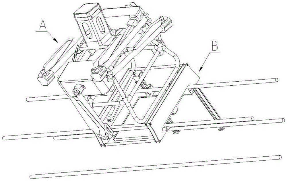
The invention discloses a multi-split wire splicing tube live flaw detection system and an application method thereof. The system comprises an upper device composed of an unmanned aerial vehicle, an industrial X-ray machine and a laser sensor, a pressing plate frame device and a vertical screw slide module , The lower part of the horizontal screw slide module, the projection imager and the linear expansion device. The drone is used as the power device for the system to go online and offline. The industrial X-ray machine is used to perform radiographic flaw detection on each connecting tube. The laser sensor is used to guide the drone to make the lower device accurately land on the connecting tube. The platen device will connect the connecting tube. Snap tightly to fix the system on the connecting pipe. When the industrial X-ray machine adjusts the angle to perform X-ray flaw detection on different connecting tubes, the lower device adjusts the appropriate position of the projection imager, so that the X-rays are projected on the projection imager, and the internal structure inspection of each connecting tube is completed. The imaging of the projection imager can accurately judge whether the internal structure of the connecting pipe is defective or not.

Figure 202111371715

Description

Multi-split conductor splicing sleeve live-line flaw detection system and application method thereof
Technical Field
The invention belongs to the field of live-line work of power transmission lines, and particularly relates to a live-line electric damage detection system for a splicing sleeve of a multi-bundle conductor and an application method thereof.
Background
Under the influence of natural factors such as ice coating, waving, oscillation and the like for a long time, the quality of the inner structure of the splicing sleeve is reduced, and the breaking force is reduced, so that the wire breakage accident is caused, and the safety and the stability of the power grid are greatly threatened. At present, the defects of the internal structure of the splicing sleeve cannot be found by ground inspection and infrared temperature measurement detection; the operation personnel go up the tower and go on the line to carry out power failure detection, the radiation protection measures of the operation personnel are incomplete, and the personnel safety risk is high; the existing unmanned detection device can only detect scratches on a single conductor, and compared with the single conductor, the on-line detection demand of a multi-split transmission conductor splicing sleeve is larger.
Disclosure of Invention
The invention aims to provide a multi-split conductor splicing sleeve electrified flaw detection device capable of really detecting internal structural defects of the multi-split conductor splicing sleeve and an application method thereof.
The invention provides an electrified injury detection system for a multi-split conductor splicing sleeve, which comprises an upper device and a lower device; the upper device comprises an unmanned aerial vehicle, an industrial X-ray machine and a laser sensor, wherein a frame type frame of the unmanned aerial vehicle is connected with a foot rest, the industrial X-ray machine is arranged at the top of the frame with a ray emitting end facing downwards, and the laser sensor is arranged on the foot rest; the lower device comprises a pressing plate frame device, a vertical screw rod sliding table module, a horizontal screw rod sliding table module, a projection imager and a linear telescopic device; the pressing plate frame device comprises a pressing plate frame and a locking device, the pressing plate frame comprises two groups of pressing plates and two groups of locking devices, the two groups of pressing plates are connected into a whole through a pull rod, the locking device comprises a locking motor and a supporting plate, the locking motor is arranged with an output shaft perpendicular to the pressing plates and fixed on the pressing plates, and the supporting plate is perpendicularly connected with the output shaft of the locking motor; the two groups of vertical screw rod sliding table modules are oppositely arranged by screw rod sliding blocks, and the tops of the sliding tables are respectively hinged with the pressing plate through rotating shafts; a bracket is arranged between the sliding blocks of the two vertical screw rod sliding table modules, and the horizontal screw rod sliding table module is upwards fixed on the bracket by the screw rod sliding blocks; the projection imager is horizontally arranged on a sliding block of the horizontal screw rod sliding table module; the linear expansion device is fixed on the side surface of the pressing plate, the tail end of an expansion rod of the linear expansion device is hinged with the upper end of one group of vertical lead screw sliding table modules, and the expansion rod expands and contracts to enable the vertical lead screw sliding table modules to rotate around the rotating shaft, so that the position of the projection imager is changed; when the upper device and the lower device are assembled, a foot rest of the unmanned aerial vehicle is fixed at the upper end of the pressing plate frame; when the system is fixed on a multi-split conductor, the pressure plate frame presses an upper-layer conductor splicing sleeve of the split conductor, and the supporting plate supports the conductor splicing sleeve and enables the conductor splicing sleeve to be clamped between the pressure plate and the supporting plate.
In an embodiment of the above technical solution, the unmanned aerial vehicle is a hexarotor type.
In an embodiment of the above technical scheme, the frame type frame is a rectangular frame, the middle position of the length direction of the frame type frame is symmetrically connected with a supporting seat, a supporting plate is rotatably connected between the two supporting seats, a T-shaped hole is formed in the central position of the supporting plate, the transmitting end of the industrial X-ray machine is arranged at the position of the T-shaped hole, and the outer cover connected through the supporting plate covers and fixes the transmitting end.
In an embodiment of the above technical scheme, two ends of the supporting plate are connected with the supporting seat through a rotating shaft and a bearing respectively, and the rotating shaft at one end is connected with a micro servo motor.
In one embodiment of the above technical scheme, the lower end of the pressing plate is provided with an upper groove, the pressing plate straddles on the lead through the upper groove, each group of pressing plates comprises two pressing plates which are arranged in parallel, and the two pressing plates are connected and fixed through a pin shaft and a sleeve outside the pin shaft.
In one embodiment of the above technical solution, the upper edge of the supporting plate has a lower groove matching with the diameter of the wire splicing sleeve.
In an embodiment of the above technical scheme, the sliding table top of the vertical screw rod sliding table module is fixed at the position corresponding to the outer side of the lead on the pressing plate, and the top of the vertical screw rod is connected with the output shaft of the servo motor through the coupler.
In an embodiment of the above technical scheme, the bracket is a U-shaped frame, and the two side arms of the bracket are respectively connected and fixed with the sliding block of the vertical screw rod sliding table module through fasteners.
In an embodiment of the above technical scheme, the slip table one end of horizontal lead screw slip table module is fixed in the intermediate position department of bracket, this end of horizontal lead screw passes through shaft coupling and servo motor's output shaft, and the last slider of horizontal lead screw is connected with and is used for the installation projection imaging appearance's mounting bracket.
The invention provides a method for carrying out charged flaw detection on a multi-split conductor splicing sleeve by using the system, which comprises the following steps:
(1) respectively assembling an upper device and a lower device, fixing a foot rest of the unmanned aerial vehicle of the upper device on a top pull rod of a pressure plate frame of the lower device, and enabling a vertical screw rod sliding table of the lower device to be in a vertical state;
(2) the sliding block of the horizontal lead screw sliding table module drives the projection imager to move outwards to a position close to the vertical lead screw sliding table module;
(3) the telescopic rod of the linear telescopic device extends out, the vertical screw rod sliding table module rotates outwards around a rotating shaft arranged on the pressing plate, and the horizontal screw rod sliding table and the projection imager are driven to swing to the outer side of an upper groove of the pressing plate during rotation;
(4) the unmanned aerial vehicle takes off above the splicing sleeve of the split conductor at most, the position relation between the whole system and the conductor is determined through the laser sensor, so that the unmanned aerial vehicle is adjusted to accurately fall down, and the pressing plate simultaneously rides on the splicing sleeve of the conductor on the upper layer through the upper groove on the bottom of the pressing plate;
(5) a locking motor on the pressing plate frame works to enable the supporting plate to rotate upwards to support and lock the wire splicing sleeve, so that the whole system is stably fixed on the upper layer wire splicing sleeve;
(6) the telescopic rod of the linear telescopic device retracts, so that the vertical lead screw sliding block module returns to a vertical state;
(7) the position of projection imaging is adjusted through the vertical lead screw sliding table module and the horizontal lead screw sliding table module, so that the position is positioned below a first lead wire splicing sleeve of the upper layer lead wire splicing sleeve;
(8) the angle of the industrial X-ray machine is adjusted, so that X-rays emitted by the industrial X-ray machine pass through the first wire splicing sleeve and then are projected on a projection imager, and the structure detection of the first wire splicing sleeve is completed;
(9) adjusting the horizontal position of the projection line imager through a horizontal screw rod sliding block module to enable the projection line imager to be positioned below a second wire of the upper-layer wire splicing sleeve, adjusting the angle of an industrial X-ray machine to enable the X-ray emitted by the industrial X-ray imager to pass through the second wire splicing sleeve and then be projected on the projection imager, and completing the structure detection of the second wire splicing sleeve until the detection of the upper-layer wire splicing sleeves is completed;
(10) repeating the steps (3) and (6);
(11) finishing detection of each wire splicing sleeve of the lower layer wire splicing sleeve according to the steps (7) to (9);
(12) repeating the step (3);
(13) a locking motor on the pressure plate frame works reversely, so that the supporting plate rotates downwards to loosen the wire splicing sleeve;
(14) the unmanned aerial vehicle takes off and returns, and the whole flaw detection work is finished.
The unmanned aerial vehicle of the upper device is used as a power device for the upper and lower wires of the whole system, the industrial X-ray machine carried on the unmanned aerial vehicle is used for carrying out radiographic inspection on each wire splicing sleeve, and the carried laser sensor is used for guiding the unmanned aerial vehicle to accurately land the lower device of the system on the wire splicing sleeve. After the lower device is landed on the wire splicing sleeve, the pressing plate of the pressing plate frame, the locking device and the supporting plate are matched to clamp the wire splicing sleeve, so that the whole system is stably fixed on the wire splicing sleeve. When the industrial X-ray machine angle of adjustment carries out X-ray inspection to different wire splicing sleeves respectively, the suitable position of projection imager is adjusted in a flexible way through the cooperation of the vertical lead screw sliding table module of lower part device and horizontal sliding table module and sharp telescoping device, makes the X-ray projection on projection imager, accomplishes the inner structure to each wire splicing sleeve and detects, can accurately judge according to projection imager's formation of image that the inner structure of splicing sleeve has the flawless. The method can well solve the problem that the current means such as daily tour, infrared temperature measurement detection, power failure detection of operating personnel, single-conductor scratch detection and the like are not suitable for detecting the structural defects in the multi-split conductor splicing sleeve.
Drawings
Fig. 1 is a schematic axial side structure diagram of a use state of one embodiment of the present invention.
Fig. 2 is an enlarged schematic view of the axial side structure of the upper device in fig. 1.
Fig. 3-5 are enlarged views of the axial side structure of the lower device of fig. 1 in different orientations.
Detailed Description
As shown in fig. 1, the electrical trauma detection system for a multi-split wire splicing sleeve disclosed in this embodiment includes an upper device a and a lower device B.
Upper portion device A mainly includes six rotor unmanned aerial vehicle, industrial X-ray production apparatus and laser sensor.
Six rotor unmanned aerial vehicle A1's frame is the rectangle frame, and the length direction bilateral symmetry of rectangle frame is connected with foot rest A11, and its length direction intermediate position department symmetric connection of length direction intermediate position department of frame has supporting seat A12, and rotatable coupling has backup pad A13 between two supporting seats, and the central point department of putting of backup pad is provided with T shape hole. The emission end of the industrial X-ray machine is arranged at the T-shaped hole and is covered and fixed by a cover A14 connected with a supporting plate.
Two ends of the supporting plate A13 are respectively connected with the supporting seat A12 through a rotating shaft and a bearing, the rotating shaft at one end is connected with a micro servo motor (not shown in the figure), and the supporting plate is driven by the servo motor to drive the industrial X-ray machine to adjust the angle, so that the angle of the industrial X-ray machine can be adjusted as required.
The laser sensor is fixed in place on a foot rest, not shown.
And the lower device B comprises a pressing plate frame device, a vertical screw rod sliding table module, a horizontal screw rod sliding table module, a projection imager and a linear telescopic device.
The pressing plate frame device comprises a pressing plate frame and a locking device, and the pressing plate frame comprises two groups of pressing plates and two groups of locking devices.
Each group of pressing plates comprises two pressing plates B1 which are arranged in parallel, the two pressing plates are fixedly connected through a pin shaft and a sleeve outside the pin shaft, and the lower end of each pressing plate B1 is provided with an upper groove as a wire splicing sleeve riding groove.
The two groups of pressure plates are connected into a whole through a pull rod B2.
The locking device comprises a locking motor B3 and a supporting plate B4, the locking motor is arranged with an output shaft perpendicular to the pressure plate B1 and is fixed on the pressure plate, and the supporting plate is perpendicularly connected with the output shaft of the locking motor. The upper edge of the supporting plate B4 is provided with a lower groove matched with the diameter of the wire splicing sleeve.
Two sets of locking devices are connected to the opposite corners of the two sets of pressing plate frames.
The two groups of vertical screw rod sliding table modules B5 are oppositely arranged by screw rod sliding blocks, the tops of the sliding tables are respectively hinged with the same end parts of the inner side pressing plates of the two groups of pressing plates through rotating shafts, and the tops of the vertical screw rods are connected with an output shaft of a servo motor through a coupler.
A bracket B6 is arranged between the sliding blocks of the two vertical lead screw sliding table modules B5, the bracket is a U-shaped frame, and the two side arms of the bracket are respectively connected and fixed with the sliding blocks of the vertical lead screw sliding table modules through fasteners.
The horizontal screw rod sliding table module B7 is upwards fixed on the bracket B6 through a screw rod sliding block.
The intermediate position department of bracket B6 is fixed in to horizontal lead screw slip table module B7's slip table one end, and this end of horizontal lead screw passes through shaft coupling and servo motor's output shaft, and the last slider of horizontal lead screw is connected with mounting bracket B8.
Projection imager B9 is horizontally mounted on mounting bracket B8.
Linear telescoping device B10 adopts electric putter, is fixed in the inboard clamp plate side of one of them a set of clamp plate, and its telescopic link end is articulated with the upper end of a set of vertical lead screw slip table module B5 wherein, and the telescopic link pole is flexible to make two sets of vertical lead screw slip table modules rotate around its pivot simultaneously, realizes projection imaging appearance B9's position change.
When upper portion device A and lower part device B equipment, six rotor unmanned aerial vehicle's foot rest firmly is fixed in on the top pull rod of pressure grillage, and vertical lead screw slip table module is in vertical state.
Six rotor unmanned aerial vehicle are as the power device of this system upper and lower line, and the industrial X-ray machine that carries on it is used for carrying out radiographic inspection for every wire splicing sleeve, and the laser sensor who carries on is used for instructing the unmanned aerial vehicle accuracy with this system accurate descending wire splicing sleeve on.
The whole online fixing and specific flaw detection process of the system is as follows:
(1) the sliding block of the horizontal lead screw sliding table module drives the projection imager to move outwards to a position close to the vertical lead screw sliding table module;
(2) the telescopic rod of the electric push rod is extended out, the two vertical screw rod sliding table modules simultaneously rotate outwards around the rotating shaft arranged on the pressing plate, and the horizontal screw rod sliding table and the projection imager are driven to swing to the outer side of the upper groove of the pressing plate during rotation;
(3) the unmanned aerial vehicle takes off above the splicing sleeve of the split conductor at most, the position relation between the whole system and the conductor is determined through the laser sensor, so that the unmanned aerial vehicle is adjusted to accurately fall down, and the pressing plate simultaneously rides on the splicing sleeve of the conductor on the upper layer through the upper groove on the bottom of the pressing plate;
(4) a locking motor on the pressing plate frame works to enable the supporting plate to rotate upwards to support and lock the wire splicing sleeve, so that the whole system is stably fixed on the upper layer wire splicing sleeve;
(5) the telescopic rod of the electric push rod retracts to enable the vertical screw rod sliding block module to return to a vertical state;
(6) the horizontal lead screw sliding table is adjusted by the vertical lead screw sliding table module to be positioned below the upper-layer guide splicing sleeve, and the horizontal position of projection imaging is adjusted by the horizontal lead screw sliding table module to be positioned below a first lead splicing sleeve of the upper-layer lead splicing sleeve;
(7) a servo motor connected with a rotating shaft at one end of a supporting plate connected with an unmanned aerial vehicle frame works to enable an industrial X-ray machine to adjust the angle, so that X-rays emitted by the industrial X-ray machine pass through a first wire splicing sleeve and then are projected on a projection imager, and the detection of the internal structure of the first wire splicing sleeve is completed;
(8) adjusting the horizontal position of the projection line imager through a horizontal screw rod sliding block module to enable the projection line imager to be positioned below a second wire of the upper-layer wire splicing sleeve, adjusting the angle of an industrial X-ray machine to enable the X-ray emitted by the industrial X-ray imager to pass through the second wire splicing sleeve and then be projected on the projection imager, and completing the structure detection of the second wire splicing sleeve until the detection of the upper-layer wire splicing sleeves is completed;
(9) repeating the steps (2) and (5);
(10) finishing detection of each wire splicing sleeve of the lower layer wire splicing sleeve by referring to the steps (6) to (8);
(11) repeating the step (2);
(12) a locking motor on the pressing plate frame works reversely, so that the supporting plate rotates downwards to loosen the wire splicing sleeve;
(13) the unmanned aerial vehicle takes off and returns, and the whole flaw detection work is finished.

Claims (10)

1. The utility model provides a many split conductor splicing sleeves electrified flaw detection system which characterized in that: the system comprises an upper device and a lower device;
the upper device comprises an unmanned aerial vehicle, an industrial X-ray machine and a laser sensor, wherein a frame type frame of the unmanned aerial vehicle is connected with a foot rest, the industrial X-ray machine is arranged at the top of the frame with a ray emitting end facing downwards, and the laser sensor is arranged on the foot rest;
the lower device comprises a plate pressing frame device, a vertical lead screw sliding table module, a horizontal lead screw sliding table module, a projection imager and a linear expansion device;
the pressing plate frame device comprises a pressing plate frame and a locking device, the pressing plate frame comprises two groups of pressing plates and two groups of locking devices, the two groups of pressing plates are connected into a whole through a pull rod, the locking device comprises a locking motor and a supporting plate, the locking motor is arranged with an output shaft perpendicular to the pressing plates and fixed on the pressing plates, and the supporting plate is perpendicularly connected with the output shaft of the locking motor;
the two groups of vertical screw rod sliding table modules are oppositely arranged by screw rod sliding blocks, and the tops of the sliding tables are respectively hinged with the pressing plate through rotating shafts;
a bracket is arranged between the sliding blocks of the two vertical screw rod sliding table modules, and the horizontal screw rod sliding table module is upwards fixed on the bracket by the screw rod sliding blocks;
the projection imager is horizontally arranged on a sliding block of the horizontal screw rod sliding table module;
the linear expansion device is fixed on the side surface of the pressing plate, the tail end of an expansion rod of the linear expansion device is hinged with the upper end of one group of vertical lead screw sliding table modules, and the expansion rod expands and contracts to enable the vertical lead screw sliding table modules to rotate around the rotating shaft, so that the position of the projection imager is changed;
when the upper device and the lower device are assembled, a foot rest of the unmanned aerial vehicle is fixed at the upper end of the pressing plate frame;
when the system is fixed on a multi-split conductor, the pressure plate frame presses an upper-layer conductor splicing sleeve of the split conductor, and the supporting plate supports the conductor splicing sleeve and enables the conductor splicing sleeve to be clamped between the pressure plate and the supporting plate.
2. The electrically energized flaw detection device for a multi-split conductor splicing sleeve of claim 1, wherein: the unmanned aerial vehicle is a hexa-rotor type.
3. The electrical tamper detection device for a multi-split conductor splicing sleeve of claim 1, wherein: frame type frame is the rectangle frame, and its length direction intermediate position department symmetric connection has a supporting seat, rotatable coupling has the backup pad between two supporting seats, and the central point of backup pad puts the department and is provided with T shape hole, T shape hole department is arranged in to industrial X-ray machine's transmitting terminal, covers fixedly through the dustcoat that the backup pad is connected.
4. The electrical tamper detection device for a multi-split conductor splicing sleeve of claim 3, wherein: the two ends of the supporting plate are connected with the supporting seat through a rotating shaft and a bearing respectively, and the rotating shaft at one end is connected with a micro servo motor.
5. The electrically energized flaw detection device for a multi-split conductor splicing sleeve of claim 1, wherein: the lower end of each pressing plate is provided with an upper groove, each pressing plate straddles on the wire through the upper groove, each group of pressing plates comprises two pressing plates which are arranged in parallel, and the two pressing plates are connected and fixed through a pin shaft and a sleeve outside the pin shaft.
6. The electrically energized flaw detection device for a multi-split conductor splicing sleeve of claim 1, wherein: the upper edge of the supporting plate is provided with a lower groove matched with the diameter of the wire splicing sleeve.
7. The electrical tamper detection device for a multi-split conductor splicing sleeve of claim 1, wherein: the top of the sliding table of the vertical lead screw sliding table module is fixed at the position, corresponding to the outer side of the lead, on the pressing plate, and the top of the vertical lead screw is connected with an output shaft of the servo motor through a coupler.
8. The electrically energized flaw detection device for a multi-split conductor splicing sleeve of claim 1, wherein: the bracket is a U-shaped frame, and two side arms of the bracket are respectively connected and fixed with the sliding block of the vertical screw rod sliding table module through fasteners.
9. The electrical tamper apparatus of claim 8, wherein: the horizontal screw rod sliding table module is characterized in that one end of the sliding table of the horizontal screw rod sliding table module is fixed at the middle position of the bracket, the end of the horizontal screw rod is connected with an output shaft of the servo motor through a coupler, and a sliding block on the horizontal screw rod is connected with a mounting frame for mounting the projection imager.
10. A method of live inspection of a multi-split conductor joint using the system of claim 1, comprising the steps of:
(1) respectively assembling an upper device and a lower device, fixing a foot rest of the unmanned aerial vehicle of the upper device on a top pull rod of a pressure plate frame of the lower device, and enabling a vertical screw rod sliding table of the lower device to be in a vertical state;
(2) the sliding block of the horizontal lead screw sliding table module drives the projection imager to move outwards to a position close to the vertical lead screw sliding table module;
(3) the telescopic rod of the linear telescopic device extends out, the vertical screw rod sliding table module rotates outwards around a rotating shaft arranged on the pressing plate, and the horizontal screw rod sliding table and the projection imager are driven to swing to the outer side of an upper groove of the pressing plate during rotation;
(4) the unmanned aerial vehicle takes off above the splicing sleeve of the split conductor at most, the position relation between the whole system and the conductor is determined through the laser sensor, so that the unmanned aerial vehicle is adjusted to accurately fall down, and the pressing plate simultaneously rides on the splicing sleeve of the conductor on the upper layer through the upper groove on the bottom of the pressing plate;
(5) a locking motor on the pressing plate frame works to enable the supporting plate to rotate upwards to support and lock the wire splicing sleeve, so that the whole system is stably fixed on the upper layer wire splicing sleeve;
(6) the telescopic rod of the linear telescopic device retracts to enable the vertical screw rod sliding block module to return to a vertical state;
(7) the position of projection imaging is adjusted through the vertical lead screw sliding table module and the horizontal lead screw sliding table module, so that the position is positioned below a first lead wire splicing sleeve of the upper layer lead wire splicing sleeve;
(8) the angle of the industrial X-ray machine is adjusted, so that X-rays emitted by the industrial X-ray machine pass through the first wire splicing sleeve and then are projected on a projection imager, and the structure detection of the first wire splicing sleeve is completed;
(9) adjusting the horizontal position of the projection line imager through a horizontal screw rod sliding block module to enable the projection line imager to be positioned below a second wire of the upper-layer wire splicing sleeve, adjusting the angle of an industrial X-ray machine to enable the X-ray emitted by the industrial X-ray imager to pass through the second wire splicing sleeve and then be projected on the projection imager, and completing the structure detection of the second wire splicing sleeve until the detection of the upper-layer wire splicing sleeves is completed;
(10) repeating the steps (3) and (6);
(11) finishing detection of each wire splicing sleeve of the lower layer wire splicing sleeve according to the steps (7) to (9);
(12) repeating the step (3);
(13) a locking motor on the pressing plate frame works reversely, so that the supporting plate rotates downwards to loosen the wire splicing sleeve;
(14) the unmanned aerial vehicle takes off and returns, and the whole flaw detection work is completed.
CN202111371715.4A 2021-11-18 2021-11-18 Multi-split conductor splicing sleeve electrified flaw detection system and application method thereof Active CN114088743B (en)

Priority Applications (2)

Application Number Priority Date Filing Date Title
CN202111371715.4A CN114088743B (en) 2021-11-18 2021-11-18 Multi-split conductor splicing sleeve electrified flaw detection system and application method thereof
US17/739,211 US11959866B2 (en) 2021-11-18 2022-05-09 Live flaw detection system for multi-bundled conductor splicing sleeve and application method thereof

Applications Claiming Priority (1)

Application Number Priority Date Filing Date Title
CN202111371715.4A CN114088743B (en) 2021-11-18 2021-11-18 Multi-split conductor splicing sleeve electrified flaw detection system and application method thereof

Publications (2)

Publication Number Publication Date
CN114088743A true CN114088743A (en) 2022-02-25
CN114088743B CN114088743B (en) 2023-06-06

Family

ID=80301973

Family Applications (1)

Application Number Title Priority Date Filing Date
CN202111371715.4A Active CN114088743B (en) 2021-11-18 2021-11-18 Multi-split conductor splicing sleeve electrified flaw detection system and application method thereof

Country Status (2)

Country Link
US (1) US11959866B2 (en)
CN (1) CN114088743B (en)

Cited By (1)

* Cited by examiner, † Cited by third party
Publication number Priority date Publication date Assignee Title
CN115575425A (en) * 2022-09-17 2023-01-06 国网吉林省电力有限公司建设分公司 Permanent magnet adsorption X-ray detection system for faults of splicing sleeve of power transmission conductor

Families Citing this family (5)

* Cited by examiner, † Cited by third party
Publication number Priority date Publication date Assignee Title
CN117388622B (en) * 2023-12-11 2024-04-09 国网浙江省电力有限公司宁波供电公司 Transmission line zero-value insulator live detection device and method based on drone
CN117969565B (en) * 2024-03-29 2024-06-04 宝鸡铭扬泵业有限公司 Pump case surface flaw detection device
CN118362586A (en) * 2024-06-20 2024-07-19 天津市塘沽永利工程有限公司 X-ray flaw detector bracket
CN118777341B (en) * 2024-09-11 2024-12-03 辽宁力德航空科技有限公司 Unmanned aerial vehicle-mounted strain clamp X-ray flaw detection device
CN119147582B (en) * 2024-11-14 2025-01-24 常州澳弘电子股份有限公司 Equipment and method for detecting heat conducting performance of circuit board

Citations (13)

* Cited by examiner, † Cited by third party
Publication number Priority date Publication date Assignee Title
CN105470867A (en) * 2016-01-05 2016-04-06 国网湖南省电力公司带电作业中心 Unmanned aerial vehicle based automatic pole-climbing method and apparatus
CN205489259U (en) * 2016-01-05 2016-08-17 国网湖南省电力公司带电作业中心 Automatically, step on lever apparatus based on unmanned aerial vehicle
CN208314114U (en) * 2018-04-09 2019-01-01 广东宏力工程检测有限公司 A kind of overhead transmission line x-ray flaw detection device
CN109668914A (en) * 2019-03-05 2019-04-23 广东电网有限责任公司 A kind of transmission line of electricity X-ray electrification failure detector and system
JP2019184414A (en) * 2018-04-10 2019-10-24 富士電機株式会社 Overhead conductor inspection system and method for inspecting overhead conductor
CN110596155A (en) * 2018-05-25 2019-12-20 广西大学 Detection actuator of UAV carrying cold cathode X-ray imaging equipment
US10613429B1 (en) * 2017-08-29 2020-04-07 Talon Aerolytics (Holding), Inc. Unmanned aerial vehicle with attached apparatus for X-ray analysis of power lines
CN210534031U (en) * 2019-08-30 2020-05-15 国网湖南省电力有限公司 Live radiation detection device for power transmission line hardware
US10816939B1 (en) * 2018-05-07 2020-10-27 Zane Coleman Method of illuminating an environment using an angularly varying light emitting device and an imager
CN112051282A (en) * 2020-08-18 2020-12-08 国网山东省电力公司临沂供电公司 A live X-ray flaw detection device and method for connecting pipes of overhead transmission lines
CN212391413U (en) * 2020-05-11 2021-01-22 南方电网能源发展研究院有限责任公司 Electric power X ray digital imaging unmanned aerial vehicle detection device and system
CN213337404U (en) * 2020-10-27 2021-06-01 内蒙古电力(集团)有限责任公司锡林郭勒电业局 A UAV for X-ray inspection of wire clips
CN213813403U (en) * 2020-09-29 2021-07-27 国网山西省电力公司电力科学研究院 An X-ray non-destructive testing device mounted on a UAV

Family Cites Families (9)

* Cited by examiner, † Cited by third party
Publication number Priority date Publication date Assignee Title
US20170285092A1 (en) * 2016-03-31 2017-10-05 U.S.A. As Represented By The Administrator Of The National Aeronautics And Space Administration Directional unmanned aerial vehicle (uav) localization of power line ultraviolet corona using point detectors
US9753461B1 (en) * 2016-04-07 2017-09-05 Google Inc. Autonomous aerial cable inspection system
US20180120196A1 (en) * 2016-10-31 2018-05-03 The Boeing Company Method and system for non-destructive testing using an unmanned aerial vehicle
US11368002B2 (en) * 2016-11-22 2022-06-21 Hydro-Quebec Unmanned aerial vehicle for monitoring an electrical line
US10597054B2 (en) * 2016-12-15 2020-03-24 Progress Rail Locomotive Inc. Real-time drone infrared inspection of moving train
CA2988156A1 (en) * 2017-12-08 2019-06-08 Quanta Associates, L.P. Unmanned aerial vehicle for use near high voltage power lines
US11220356B2 (en) * 2019-01-02 2022-01-11 The Boeing Company Non-destructive inspection using unmanned aerial vehicle
WO2020198877A1 (en) * 2019-04-04 2020-10-08 Atomic Energy Of Canada Limited / Énergie Atomique Du Canada Limitée Radiation detection device with directional radiation detector
JP7514704B2 (en) * 2020-09-01 2024-07-11 キヤノンメディカルシステムズ株式会社 X-ray tube holding device and X-ray imaging system

Patent Citations (13)

* Cited by examiner, † Cited by third party
Publication number Priority date Publication date Assignee Title
CN205489259U (en) * 2016-01-05 2016-08-17 国网湖南省电力公司带电作业中心 Automatically, step on lever apparatus based on unmanned aerial vehicle
CN105470867A (en) * 2016-01-05 2016-04-06 国网湖南省电力公司带电作业中心 Unmanned aerial vehicle based automatic pole-climbing method and apparatus
US10613429B1 (en) * 2017-08-29 2020-04-07 Talon Aerolytics (Holding), Inc. Unmanned aerial vehicle with attached apparatus for X-ray analysis of power lines
CN208314114U (en) * 2018-04-09 2019-01-01 广东宏力工程检测有限公司 A kind of overhead transmission line x-ray flaw detection device
JP2019184414A (en) * 2018-04-10 2019-10-24 富士電機株式会社 Overhead conductor inspection system and method for inspecting overhead conductor
US10816939B1 (en) * 2018-05-07 2020-10-27 Zane Coleman Method of illuminating an environment using an angularly varying light emitting device and an imager
CN110596155A (en) * 2018-05-25 2019-12-20 广西大学 Detection actuator of UAV carrying cold cathode X-ray imaging equipment
CN109668914A (en) * 2019-03-05 2019-04-23 广东电网有限责任公司 A kind of transmission line of electricity X-ray electrification failure detector and system
CN210534031U (en) * 2019-08-30 2020-05-15 国网湖南省电力有限公司 Live radiation detection device for power transmission line hardware
CN212391413U (en) * 2020-05-11 2021-01-22 南方电网能源发展研究院有限责任公司 Electric power X ray digital imaging unmanned aerial vehicle detection device and system
CN112051282A (en) * 2020-08-18 2020-12-08 国网山东省电力公司临沂供电公司 A live X-ray flaw detection device and method for connecting pipes of overhead transmission lines
CN213813403U (en) * 2020-09-29 2021-07-27 国网山西省电力公司电力科学研究院 An X-ray non-destructive testing device mounted on a UAV
CN213337404U (en) * 2020-10-27 2021-06-01 内蒙古电力(集团)有限责任公司锡林郭勒电业局 A UAV for X-ray inspection of wire clips

Non-Patent Citations (1)

* Cited by examiner, † Cited by third party
Title
梁华贵;许义;路健;朱先启;: "浅谈X射线检测在架空输电线路耐张线夹的应用", 电工技术, no. 24 *

Cited By (2)

* Cited by examiner, † Cited by third party
Publication number Priority date Publication date Assignee Title
CN115575425A (en) * 2022-09-17 2023-01-06 国网吉林省电力有限公司建设分公司 Permanent magnet adsorption X-ray detection system for faults of splicing sleeve of power transmission conductor
CN115575425B (en) * 2022-09-17 2023-10-24 国网吉林省电力有限公司建设分公司 Permanent magnet adsorption X-ray detection system for fault of power transmission wire splicing sleeve

Also Published As

Publication number Publication date
CN114088743B (en) 2023-06-06
US11959866B2 (en) 2024-04-16
US20230152247A1 (en) 2023-05-18

Similar Documents

Publication Publication Date Title
CN114088743A (en) Multi-split conductor splicing sleeve live-line flaw detection system and application method thereof
CN115047061B (en) Nondestructive testing device and method for strain clamp of ultra-high voltage transmission line
CN118010167A (en) Integrated detection device of power failure equipment
CN118067750A (en) X-ray detection device and method for strain clamp of four-split conductor of power transmission line
CN110571703B (en) Overhead line foreign body remover and foreign body removal method
CN216309845U (en) On-line fixing device of multi-bundle conductor splicing sleeve electrified injury detection system
CN109873363A (en) Extra high voltage direct current transmission line method for inspecting
CN116106338B (en) X-ray detection device and method for tension clamps used in multi-split lines
CN115372377B (en) Distribution network line fault detection positioning equipment
CN116908227A (en) Nondestructive testing device and method for strain clamp of ultra-high voltage transmission line
CN120761919A (en) A test device for automobile central control connection harness
CN222087615U (en) A four-split conductor tension clamp detection device
CN220688801U (en) Steam pipeline defect detection device
CN118992155A (en) Unmanned aerial vehicle-based transmission line flaw detection robot
CN115825123B (en) Electrified joint detection device and method for helicopter of overhead transmission line
CN216309820U (en) Multi-connecting-rod linkage camera shooting platform
CN117110796A (en) Wind power generation cable fault online detection device and detection method
CN222484119U (en) High-efficient line inspection device for line maintenance
CN209540428U (en) Can obstacle detouring high pressure camera installation rack
CN220741178U (en) Automatic patrol robot based on X-ray detection
CN118358781B (en) Flying robot device and method for monitoring cable-stayed cable and application of flying robot device and method
CN119881527B (en) Accurate capturing and positioning device for fault points of power transmission line
CN115675959B (en) A marketing brain data center inspection robot
CN115331948B (en) A network transformer foot winding machine and foot winding method
CN221840921U (en) Tester for detecting semiconductor device

Legal Events

Date Code Title Description
PB01 Publication
PB01 Publication
SE01 Entry into force of request for substantive examination
GR01 Patent grant
GR01 Patent grant
CB03 Change of inventor or designer information

Inventor after: Zou Dehua

Inventor after: Leng Tao

Inventor after: Yang Jiani

Inventor after: Xiao Qiaosha

Inventor after: He Zhiqiang

Inventor after: Xi Chongyu

Inventor after: Zhou Mingzhu

Inventor after: Xie Yugan

Inventor after: Wang Dongli

Inventor after: Chen Jianping

Inventor after: Wang Chenfeng

Inventor before: Zou Dehua

Inventor before: Leng Tao

Inventor before: Yang Jiani

Inventor before: Xiao Qiaosha

Inventor before: He Zhiqiang

Inventor before: Xi Chongyu

Inventor before: Zhou Mingzhu

Inventor before: Xie Yugan

Inventor before: Wang Dongli

Inventor before: Chen Jianping

Inventor before: Wang Chenfeng

CP03 Change of name, title or address

Address after: 410004 398 new Shao Dong Road, Tianxin District, Changsha, Hunan

Patentee after: STATE GRID HUNAN ELECTRIC POWER Co.,Ltd.

Country or region after: China

Patentee after: Super high voltage transmission company of State Grid Hunan Electric Power Co.,Ltd.

Patentee after: STATE GRID CORPORATION OF CHINA

Address before: 410004 398 new Shao Dong Road, Tianxin District, Changsha, Hunan

Patentee before: STATE GRID HUNAN ELECTRIC POWER Co.,Ltd.

Country or region before: China

Patentee before: State Grid Hunan Electric Power Co.,Ltd. Power Transmission Overhaul Branch

Patentee before: STATE GRID CORPORATION OF CHINA