CN114088726A - Pipeline welding seam surface defect detection platform - Google Patents
Pipeline welding seam surface defect detection platform Download PDFInfo
- Publication number
- CN114088726A CN114088726A CN202111495060.1A CN202111495060A CN114088726A CN 114088726 A CN114088726 A CN 114088726A CN 202111495060 A CN202111495060 A CN 202111495060A CN 114088726 A CN114088726 A CN 114088726A
- Authority
- CN
- China
- Prior art keywords
- module
- infrared
- data
- image
- trolley
- Prior art date
- Legal status (The legal status is an assumption and is not a legal conclusion. Google has not performed a legal analysis and makes no representation as to the accuracy of the status listed.)
- Granted
Links
Images


Classifications
-
- G—PHYSICS
- G01—MEASURING; TESTING
- G01N—INVESTIGATING OR ANALYSING MATERIALS BY DETERMINING THEIR CHEMICAL OR PHYSICAL PROPERTIES
- G01N21/00—Investigating or analysing materials by the use of optical means, i.e. using sub-millimetre waves, infrared, visible or ultraviolet light
- G01N21/84—Systems specially adapted for particular applications
- G01N21/88—Investigating the presence of flaws or contamination
- G01N21/8806—Specially adapted optical and illumination features
-
- B—PERFORMING OPERATIONS; TRANSPORTING
- B62—LAND VEHICLES FOR TRAVELLING OTHERWISE THAN ON RAILS
- B62D—MOTOR VEHICLES; TRAILERS
- B62D63/00—Motor vehicles or trailers not otherwise provided for
- B62D63/02—Motor vehicles
-
- F—MECHANICAL ENGINEERING; LIGHTING; HEATING; WEAPONS; BLASTING
- F17—STORING OR DISTRIBUTING GASES OR LIQUIDS
- F17D—PIPE-LINE SYSTEMS; PIPE-LINES
- F17D5/00—Protection or supervision of installations
- F17D5/02—Preventing, monitoring, or locating loss
-
- G—PHYSICS
- G01—MEASURING; TESTING
- G01N—INVESTIGATING OR ANALYSING MATERIALS BY DETERMINING THEIR CHEMICAL OR PHYSICAL PROPERTIES
- G01N21/00—Investigating or analysing materials by the use of optical means, i.e. using sub-millimetre waves, infrared, visible or ultraviolet light
- G01N21/84—Systems specially adapted for particular applications
- G01N21/88—Investigating the presence of flaws or contamination
- G01N21/8851—Scan or image signal processing specially adapted therefor, e.g. for scan signal adjustment, for detecting different kinds of defects, for compensating for structures, markings, edges
-
- G—PHYSICS
- G01—MEASURING; TESTING
- G01N—INVESTIGATING OR ANALYSING MATERIALS BY DETERMINING THEIR CHEMICAL OR PHYSICAL PROPERTIES
- G01N21/00—Investigating or analysing materials by the use of optical means, i.e. using sub-millimetre waves, infrared, visible or ultraviolet light
- G01N21/84—Systems specially adapted for particular applications
- G01N21/88—Investigating the presence of flaws or contamination
- G01N21/95—Investigating the presence of flaws or contamination characterised by the material or shape of the object to be examined
- G01N21/954—Inspecting the inner surface of hollow bodies, e.g. bores
-
- G—PHYSICS
- G01—MEASURING; TESTING
- G01S—RADIO DIRECTION-FINDING; RADIO NAVIGATION; DETERMINING DISTANCE OR VELOCITY BY USE OF RADIO WAVES; LOCATING OR PRESENCE-DETECTING BY USE OF THE REFLECTION OR RERADIATION OF RADIO WAVES; ANALOGOUS ARRANGEMENTS USING OTHER WAVES
- G01S19/00—Satellite radio beacon positioning systems; Determining position, velocity or attitude using signals transmitted by such systems
- G01S19/38—Determining a navigation solution using signals transmitted by a satellite radio beacon positioning system
- G01S19/39—Determining a navigation solution using signals transmitted by a satellite radio beacon positioning system the satellite radio beacon positioning system transmitting time-stamped messages, e.g. GPS [Global Positioning System], GLONASS [Global Orbiting Navigation Satellite System] or GALILEO
- G01S19/42—Determining position
-
- G—PHYSICS
- G01—MEASURING; TESTING
- G01N—INVESTIGATING OR ANALYSING MATERIALS BY DETERMINING THEIR CHEMICAL OR PHYSICAL PROPERTIES
- G01N21/00—Investigating or analysing materials by the use of optical means, i.e. using sub-millimetre waves, infrared, visible or ultraviolet light
- G01N21/84—Systems specially adapted for particular applications
- G01N21/88—Investigating the presence of flaws or contamination
- G01N21/8851—Scan or image signal processing specially adapted therefor, e.g. for scan signal adjustment, for detecting different kinds of defects, for compensating for structures, markings, edges
- G01N2021/8887—Scan or image signal processing specially adapted therefor, e.g. for scan signal adjustment, for detecting different kinds of defects, for compensating for structures, markings, edges based on image processing techniques
-
- G—PHYSICS
- G01—MEASURING; TESTING
- G01N—INVESTIGATING OR ANALYSING MATERIALS BY DETERMINING THEIR CHEMICAL OR PHYSICAL PROPERTIES
- G01N2201/00—Features of devices classified in G01N21/00
- G01N2201/10—Scanning
- G01N2201/103—Scanning by mechanical motion of stage
-
- G—PHYSICS
- G01—MEASURING; TESTING
- G01N—INVESTIGATING OR ANALYSING MATERIALS BY DETERMINING THEIR CHEMICAL OR PHYSICAL PROPERTIES
- G01N2201/00—Features of devices classified in G01N21/00
- G01N2201/12—Circuits of general importance; Signal processing
- G01N2201/126—Microprocessor processing
- G01N2201/1263—Microprocessor is used as variant to separate part circuits
Landscapes
- Engineering & Computer Science (AREA)
- Physics & Mathematics (AREA)
- Chemical & Material Sciences (AREA)
- General Physics & Mathematics (AREA)
- Health & Medical Sciences (AREA)
- Biochemistry (AREA)
- Remote Sensing (AREA)
- Pathology (AREA)
- Immunology (AREA)
- General Health & Medical Sciences (AREA)
- Radar, Positioning & Navigation (AREA)
- Life Sciences & Earth Sciences (AREA)
- Analytical Chemistry (AREA)
- Mechanical Engineering (AREA)
- Computer Networks & Wireless Communication (AREA)
- Transportation (AREA)
- Combustion & Propulsion (AREA)
- Computer Vision & Pattern Recognition (AREA)
- Signal Processing (AREA)
- General Engineering & Computer Science (AREA)
- Investigating Materials By The Use Of Optical Means Adapted For Particular Applications (AREA)
Abstract
The application relates to the technical field of pipeline weld joint defect detection, and discloses a pipeline weld joint surface defect detection platform which comprises a motion control module, an image acquisition module, a data cache module and a GUI (graphical user interface) display module, wherein the motion control module comprises an infrared trolley and an infrared pan-tilt, the image acquisition module comprises a camera, the camera is arranged on the infrared trolley, and a GPS (global positioning system) positioner is also arranged on the infrared trolley; the data collected by the image collection module is stored in a data cache module; the GUI display module comprises a VGA display and a UDP biographical chart, and the data cache module is connected with the VGA display and the UDP biographical chart and displays the VGA display and the UDP biographical chart on a GUI interface in real time. According to the invention, through real-time and efficient imaging, a worker is assisted to perform weld joint detection in a pipeline which cannot enter and has a complex environment, defects are visually and comprehensively identified, and a reasonable basis is provided for safety evaluation of the pipeline; the design of the invention has the advantages of small volume, low power consumption, high processing speed, low cost and the like.
Description
Technical Field
The application relates to the technical field of pipeline weld joint defect detection, in particular to a pipeline weld joint surface defect detection platform.
Background
The traditional welding seam detection technology is professional technicians, and whether welding defects exist in a pipeline or not is judged by using professional knowledge and years of working experience, so that the welding seam detection has certain subjectivity.
At present, welding seam defects are detected by X-rays, but due to the high cost of X-ray imaging, the detection of the prior welding seam defects can be carried out by the design for general welding seam defect detection and pretreatment.
Disclosure of Invention
Aiming at the defects in the prior art, the invention aims to provide a pipeline welding seam surface defect detection platform.
In order to achieve the purpose, the invention adopts the following technical scheme:
a pipeline welding seam surface defect detection platform comprises a motion control module, an image acquisition module, a data cache module and a GUI display module, wherein the motion control module comprises an infrared trolley and an infrared pan-tilt, the image acquisition module comprises a camera, the infrared trolley can remotely control the trolley to advance and retreat through an infrared remote controller, the camera is arranged on the infrared trolley, a GPS (global positioning system) positioner is further arranged on the infrared trolley, and the infrared pan-tilt rotates the camera through remote control; the data collected by the image collection module is stored in a data cache module; the GUI display module comprises a VGA display and a UDP biographical chart, and the data cache module is connected with the VGA display and the UDP biographical chart and displays the VGA display and the UDP biographical chart on a GUI interface in real time.
The pipeline welding seam surface defect detection platform further comprises an image preprocessing module, data collected by the image collection module are processed by the image preprocessing module and then stored in a data cache module, the image preprocessing module reads original image data, then the data are processed by an RGB-to-gray sub module and an edge detection module using a Sobel operator, after the image data are read, the original RGB565 data are grayed firstly, a slidable 3 x 3 window is formed, the image data of the neighborhood are convoluted by using the image preprocessing module, a central target pixel point is binarized according to a set threshold value, edge information of the image is extracted, graying, reading of 3 x 3 matrix pixels and extraction of feature information can be achieved through the whole module, and finally an image processing result is obtained.
Preferably, the infrared trolley is controlled by an STM32 microprocessor.
Furthermore, magnets are added on wheels of the infrared trolley, so that the trolley can move in the pipeline for 360 degrees.
Further, the motors of the infrared trolley comprise four direct current motors, and the driving circuit formed by the L298N chip is used for driving the four direct current motors of the infrared trolley.
Furthermore, the infrared cloud platform comprises a direct current motor, a motor controller, a speed reducer and a proportional potentiometer, wherein the speed reducer is installed on an output shaft of the direct current motor, the power output shaft of the speed reducer is provided with the proportional potentiometer (or other angle sensors), the potentiometer is used for sending information to the motor controller after detecting the rotation angle of the power output shaft of the speed reducer, the motor controller generates control pulses and drives a motor (motor) to rotate to control the output position of a gear set, and the purpose of accurate positioning is achieved.
Preferably, the camera is an OV7670 CMOS camera (image collector) of OV company, the OV7670 is connected to an FPGA, and the FPGA is used as a data acquisition and analysis chip.
Furthermore, the data caching module adopts SDRAM, namely synchronous dynamic random access memory.
The data cache module divides the SDRAM controller into 5 sub-modules by adopting a top-down design mode, wherein the SDRAM logic control module is mainly responsible for switching SDRAM operation commands; the refreshing submodule is mainly used for charging the SDRAM and continuously refreshing the SDRAM at intervals of 64ms to ensure that internal data are not lost; the initialization submodule is used for setting the read-write burst length and the sequential working mode of the SDRAM; the writing submodule mainly realizes the storage of original data; the read submodule is mainly used for orderly reading out pixel data written in the read submodule.
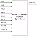
Preferably, the present invention uses a chip model MT48LC32M16A2 from MICRON.
Further, the data collected by the image collection module is converted from 8 bits to 16 bits and stored in the SDRAM before entering the image preprocessing module.
Preferably, the VGA display adopts a progressive scanning mode, and the UDP pictogram adopts a network communication protocol transmission mode.
Furthermore, the interface display in the GUI display module is designed by adopting a Qt creator tool, the obtained real-time video signal is transmitted to the GUI display through a UDP protocol, the position information is extracted by utilizing the real-time information obtained by the GPS positioner and displayed on the interface in real time, the stored picture information and the position information are stored by utilizing database software, and a table is established through SQL table establishing statements, wherein the table comprises the GPS position information and the defect information.
Compared with the prior art, the invention has the following beneficial effects:
(1) according to the invention, through real-time and efficient imaging, a worker is assisted to detect a welding seam in a pipeline which cannot enter and has a complex environment, and the camera is steered in real time through the driving trolley and the cradle head, so that the defect can be visually and comprehensively identified, and a reasonable basis is provided for the safety evaluation of the pipeline;
(2) the welding seam detection trolley controlled by the STM32 enters the pipeline, and the ARM + FPGA framework can not only give full play to the high real-time performance of the FPGA, but also make the high performance and low power consumption of the ARM framework and the expansion of later system functions give full play to the advantages of the ARM framework; the position of the trolley in the pipeline can be accurately positioned through the GPS positioning module; the camera can rotate 360 degrees through the holder, and the defects of the welding line in the pipeline are fully collected; the information is stored in the database, so that later workers can repair the weld defects conveniently, and the method has the characteristics of low cost and simplicity and convenience in operation;
(3) the design of the invention has the advantages of small volume, low power consumption, high processing speed, low cost and the like, the design product is more efficient by depending on an edge detection algorithm and the ping-pong operation of SDRAM, and meanwhile, the information in the pipeline is more visual by real-time interface display; the FPGA is used as a data acquisition and analysis chip, so that the real-time performance is good, the filtering and edge detection of the image can be carried out, and the real-time extraction and display of the weld joint features can be realized depending on the pipeline technology, the concurrent processing of the data, the simultaneous receiving and the simultaneous processing.
Drawings
Other features, objects and advantages of the invention will become more apparent upon reading of the detailed description of non-limiting embodiments with reference to the following drawings:
FIG. 1 is a diagram of a pipeline weld surface defect detection platform;
FIG. 2 shows the operating principle of an infrared pan/tilt head;
FIG. 3 is a functional block diagram of OV 7670;
FIG. 4 is a schematic diagram of OV7670 and FPGA hardware connection;
FIG. 5 is a pin diagram of MT48LC32M16A2 chip
FIG. 6 is a diagram of SDRAM operation;
FIG. 7 is a schematic diagram of a VGA interface;
FIG. 8 is a weld defect detection interface.
Detailed Description
The present invention will be described in detail with reference to specific examples. The following examples will assist those skilled in the art in further understanding the invention, but are not intended to limit the invention in any way. It should be noted that variations and modifications can be made by persons skilled in the art without departing from the spirit of the invention. All falling within the scope of the present invention.
A pipeline welding seam surface defect detection platform comprises a motion control module, an image acquisition module, a data cache module and a GUI display module, wherein the motion control module comprises an infrared trolley and an infrared pan-tilt, the image acquisition module comprises a camera, the infrared trolley can remotely control the trolley to move forwards and backwards through an infrared remote controller, the camera is arranged on the infrared trolley, a GPS (global positioning system) positioner is further arranged on the infrared trolley, and the infrared pan-tilt rotates the camera through remote control, so that images at different angles can be conveniently presented, and convenience is brought to omnibearing detection of a welding seam; the data collected by the image collection module is stored in a data cache module; the GUI display module comprises a VGA display and a UDP biographical chart, and the data cache module is connected with the VGA display and the UDP biographical chart and displays the VGA display and the UDP biographical chart on a GUI interface in real time. As shown in FIG. 1, it is a real object diagram of the platform for detecting surface defects of a weld joint of a pipeline according to the present invention.
The pipeline welding seam surface defect detection platform further comprises an image preprocessing module, data collected by the image collection module are processed by the image preprocessing module and then stored in a data cache module, the image preprocessing module reads original image data, then the data are processed by an RGB-to-gray sub module and an edge detection module using a Sobel operator, after the image data are read, the original RGB565 data are grayed firstly, a slidable 3 x 3 window is formed, the image data of the neighborhood are convoluted by using the image preprocessing module, a central target pixel point is binarized according to a set threshold value, edge information of the image is extracted, graying, reading of 3 x 3 matrix pixels and extraction of feature information can be achieved through the whole module, and finally an image processing result is obtained.
Furthermore, magnets are added on wheels of the infrared trolley, so that the trolley can move in the pipeline for 360 degrees.
Further, the motors of the infrared trolley comprise four direct current motors, and the driving circuit formed by the L298N chip is used for driving the four direct current motors of the infrared trolley.
Furthermore, the infrared cloud platform comprises a direct current motor, a motor controller, a speed reducer and a proportional potentiometer, wherein the speed reducer is installed on an output shaft of the direct current motor, the power output shaft of the speed reducer is provided with the proportional potentiometer (other angle sensors), the potentiometer is used for sending information to the motor controller after detecting the rotation angle of the power output shaft of the speed reducer, the motor controller generates control pulses and drives a motor (motor) to rotate to control the output position of a gear set, and the purpose of accurate positioning is achieved. The working principle is shown in figure 2.
The infrared cloud platform is a servo unit which encapsulates the components in a shell convenient to install. By using the infrared cradle head, the cradle head can be controlled to automatically rotate to a relatively accurate angle by receiving a simple controller instruction.
L298N is a high voltage, high current motor driver chip manufactured by ST corporation. The chip is packaged by adopting 15 pins and is mainly characterized in that: the working voltage is high, and the highest working voltage can reach 46V; the output current is large, the instantaneous peak current can reach 3A, and the continuous working current can reach 2A; rated power 25W. The high-voltage large-current full-bridge driver with two H bridges is used for driving loads such as a direct current motor, a stepping motor and the like. In addition, the control is carried out by adopting a standard logic level signal, and one chip can drive one two-phase stepping motor or a dead-phase stepping motor and can also drive two direct current motors.
The camera is an OV7670 CMOS camera (image collector) of OV company, the OV7670 is connected with an FPGA, and the FPGA is used as a data acquisition and analysis chip.
The OV7670 CMOS image collector (camera) is mainly characterized by small volume, high sensitivity and low price, its photosensitive pixel is 640X480, its output format is RGB565, it has the functions of controlling image zoom and automatically regulating noise reduction, the image information with 8 bit resolution can be captured, it has the high-speed image collecting capability of 30 frames/second, and it can configure various registers through SCCB bus, and can collect the image according to the design requirement.
Fig. 3 is a functional block diagram of OV7670, which has 6 modules, respectively, as SCCB bus interface module, image analog-to-digital conversion module, test pattern module, image timing module, image sensing array module and DSP data output module. The SCCB bus interface is mainly used for configuring a plurality of registers in the image collector; the image analog-digital conversion module is used for converting an analog signal into a digital signal through the module, so that the synchronous use of pixel frequency is realized; the test pattern generation module mainly tests the size and pixels of the pattern according to the number of the color bars generated by the test pattern generation module; the image time sequence module mainly controls the distribution of the internal time sequence of the module and outputs an external time sequence signal; the array of image sensors is 656x488, but the effective array is 640x 480.
FIG. 4 is a schematic diagram of hardware connection between OV7670 and FPGA, where pi _ clk is an output 24MHZ clock line for implementing synchronous transmission of data between FPGA and OV 7670; pi _ rst _ n is a reset signal provided by the FPGA for the image acquisition sensor; pi _ comd _ data is digital image data output by the OV7670, pi _ coms _ hs is a column synchronization signal, and when the pi _ comd _ data is at a high level, the data transmitted to the FPGA by the camera is valid data; pi _ coms _ vs is a column synchronization signal indicating the end of the previous frame image and the start of the next frame image; the sccb _ clk is provided for the communication clock line of the camera by the FPGA and used for configuring the internal register of the camera; sccb _ sda is a serial bidirectional data line for transmitting device addresses, register addresses and configuration data of the camera.
Furthermore, the data cache module adopts SDRAM, namely synchronous dynamic random access memory, and the synchronization means that the clock frequency of the data cache module is the same as the system clock frequency of the front-end bus, and the sending of internal commands and the transmission of data take the data cache module as the reference; dynamic means that the memory array needs to be refreshed continuously to ensure that data is not lost, and random means that data is not stored in sequence linearly, but read and write data by freely designating addresses. The SDRAM can keep all input and output signals synchronized with the system clock. And a pipeline processing mode is adopted in synchronization with a system clock, and when a specific address is specified, a plurality of data can be read, namely burst transmission is realized.
The data cache module divides the SDRAM controller into 5 sub-modules by adopting a top-down design mode, wherein the SDRAM logic control module is mainly responsible for switching SDRAM operation commands; the refreshing submodule is mainly used for charging the SDRAM and continuously refreshing the SDRAM at intervals of 64ms to ensure that internal data are not lost; the initialization submodule is used for setting the read-write burst length and the sequential working mode of the SDRAM; the writing submodule mainly realizes the storage of original data; the read submodule is mainly used for orderly reading out pixel data written in the read submodule.
The present embodiment adopts a chip of model MT48LC32M16a2 from MICRON, whose memory architecture is SDRAM (8Meg x 16 x 4banks), and MT48LC32M16 adopts 54-pin TSOP package, whose operating voltage is 3.3V, and adopts a synchronous interface mode (all signals are triggered by the rising edge of the clock signal) to synchronize with the system clock. It contains a 16-bit data bus, 4 banks. The number of row addresses per bank is 13 and the number of column addresses is 10. Its main pins are shown in fig. 5.
The SDRAM has the following characteristics:
1. the address lines of SDRAM provide different addresses under different commands by adopting the principle of row and column address multiplexing. The row and column address multiplexes 13 address lines.
2. The refresh rate is 8192 times within 64 ms.
3. When reading and writing, the row needs to be activated first. When page-changing read-write, the closed row needs to be precharged, and then a new row is activated to read-write.
The mode register must be configured before the SDRAM operates normally.
The basic operating principle of SDRAM is shown in fig. 6.
Further, the data collected by the image collection module is spliced before entering the image preprocessing module, so that the conversion from 8 bits to 16 bits is completed.
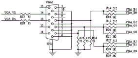
The VGA display is divided into progressive scanning and interlaced scanning: the line-by-line scanning is that the scanning is performed from the first point at the upper left corner of the screen point by point from left to right, and after one line is scanned, the electron beam returns to the initial position of the next line on the left side of the screen, during which period the CRT blanks the electron beam, and when each line is finished, the synchronization is performed by using a line synchronization signal; when all lines are scanned, a frame is formed, field synchronization is carried out by using a field synchronization signal, scanning is returned to the upper left of the screen, and simultaneously field blanking is carried out to start the next frame. Interlaced scanning means that every other line is scanned during electron beam scanning, and the rest lines are scanned by returning after scanning a screen, and an interlaced scanning display flickers quickly and possibly causes eye fatigue of a user, so that the invention adopts a progressive scanning mode. Fig. 7 is a schematic diagram of a VGA interface.
The UDP biography graph adopts a network communication protocol transmission mode. The UDP has no congestion control, the application layer can better control the data to be transmitted and the transmission time, and the congestion control in the network can not influence the transmission rate of the host. Some real-time applications require transmission at a steady rate, tolerate some data loss, but do not allow for large delays, and are designed with great real-time benefits in this system.
Further, the interface display in the GUI display module is designed by tools such as Qt creator and the like, the obtained real-time video signal is transmitted to the GUI display through a UDP protocol, the position information is extracted by using the real-time information obtained by the GPS positioner and displayed on the interface in real time, the stored picture information and the position information are stored by using database software, a table is established through SQL table establishing sentences, the table comprises the GPS position information and the defect information, and convenience is provided for later-stage workers to repair the defects. As shown in fig. 8, a widget window is created for Qt creator.
Qt was a cross-platform C + + gui application development framework developed by Qt Company in 1991. It can be used to develop both GUI and non-GUI programs, such as console tools and servers. Qt is an Object-oriented framework that is easily extended and allows true component programming using special code generation extensions called Meta Object Compiler (moc) and some macros.
The foregoing description of specific embodiments of the present invention has been presented. It is to be understood that the present invention is not limited to the specific embodiments described above, and that various changes and modifications may be made by one skilled in the art within the scope of the appended claims without departing from the spirit of the invention.
Claims (10)
Priority Applications (1)
| Application Number | Priority Date | Filing Date | Title |
|---|---|---|---|
| CN202111495060.1A CN114088726B (en) | 2021-12-08 | 2021-12-08 | Pipeline weld surface defect detection platform |
Applications Claiming Priority (1)
| Application Number | Priority Date | Filing Date | Title |
|---|---|---|---|
| CN202111495060.1A CN114088726B (en) | 2021-12-08 | 2021-12-08 | Pipeline weld surface defect detection platform |
Publications (2)
| Publication Number | Publication Date |
|---|---|
| CN114088726A true CN114088726A (en) | 2022-02-25 |
| CN114088726B CN114088726B (en) | 2024-04-02 |
Family
ID=80306930
Family Applications (1)
| Application Number | Title | Priority Date | Filing Date |
|---|---|---|---|
| CN202111495060.1A Expired - Fee Related CN114088726B (en) | 2021-12-08 | 2021-12-08 | Pipeline weld surface defect detection platform |
Country Status (1)
| Country | Link |
|---|---|
| CN (1) | CN114088726B (en) |
Cited By (3)
| Publication number | Priority date | Publication date | Assignee | Title |
|---|---|---|---|---|
| CN115049600A (en) * | 2022-05-31 | 2022-09-13 | 哈尔滨工程大学 | Intelligent identification system and method for small sample pipeline defects |
| CN115541612A (en) * | 2022-10-02 | 2022-12-30 | 重庆蕴明科技股份有限公司 | Data acquisition terminal |
| CN116008304A (en) * | 2022-12-12 | 2023-04-25 | 上海森松制药设备工程有限公司 | A welding seam inspection method suitable for pipeline interior |
Citations (12)
| Publication number | Priority date | Publication date | Assignee | Title |
|---|---|---|---|---|
| KR20120073870A (en) * | 2010-12-27 | 2012-07-05 | 한국철도기술연구원 | Apparatus and the method for defect detection of weldments in railway bogie |
| US20120218411A1 (en) * | 2011-02-25 | 2012-08-30 | Guangzhou Sat Infrared Technology Co. Ltd | System and method for road surface defects detection |
| CN105635648A (en) * | 2014-10-28 | 2016-06-01 | 江苏绿扬电子仪器集团有限公司 | Video real-time edge detection system |
| JP2017083414A (en) * | 2015-10-30 | 2017-05-18 | 株式会社東芝 | Defect detection device and defect detection method |
| CN207503284U (en) * | 2017-11-09 | 2018-06-15 | 郑州艾毅电子科技有限公司 | Image Edge-Detection system |
| US20180293725A1 (en) * | 2015-12-14 | 2018-10-11 | Nikon-Trimble Co., Ltd. | Defect detection apparatus and program |
| CN111257343A (en) * | 2020-03-02 | 2020-06-09 | 中国石油大学(华东) | Device, system and method for detecting quality of inner surface of pipeline welding seam |
| CN211148459U (en) * | 2019-10-28 | 2020-07-31 | 扬州大学 | Port crane walking track surface defect detection device |
| CN111982936A (en) * | 2020-08-25 | 2020-11-24 | 绍兴市特种设备检测院 | X-ray automatic detection device for heat exchanger tube-tube plate welding seam |
| CN112986252A (en) * | 2019-12-16 | 2021-06-18 | 中车唐山机车车辆有限公司 | Motor train unit bottom plate inspection system |
| CN113409355A (en) * | 2021-05-13 | 2021-09-17 | 杭州电子科技大学 | Moving target identification system and method based on FPGA |
| CN113640316A (en) * | 2021-09-08 | 2021-11-12 | 山东华宇工学院 | Spherical tank weld inspection robot |
-
2021
- 2021-12-08 CN CN202111495060.1A patent/CN114088726B/en not_active Expired - Fee Related
Patent Citations (12)
| Publication number | Priority date | Publication date | Assignee | Title |
|---|---|---|---|---|
| KR20120073870A (en) * | 2010-12-27 | 2012-07-05 | 한국철도기술연구원 | Apparatus and the method for defect detection of weldments in railway bogie |
| US20120218411A1 (en) * | 2011-02-25 | 2012-08-30 | Guangzhou Sat Infrared Technology Co. Ltd | System and method for road surface defects detection |
| CN105635648A (en) * | 2014-10-28 | 2016-06-01 | 江苏绿扬电子仪器集团有限公司 | Video real-time edge detection system |
| JP2017083414A (en) * | 2015-10-30 | 2017-05-18 | 株式会社東芝 | Defect detection device and defect detection method |
| US20180293725A1 (en) * | 2015-12-14 | 2018-10-11 | Nikon-Trimble Co., Ltd. | Defect detection apparatus and program |
| CN207503284U (en) * | 2017-11-09 | 2018-06-15 | 郑州艾毅电子科技有限公司 | Image Edge-Detection system |
| CN211148459U (en) * | 2019-10-28 | 2020-07-31 | 扬州大学 | Port crane walking track surface defect detection device |
| CN112986252A (en) * | 2019-12-16 | 2021-06-18 | 中车唐山机车车辆有限公司 | Motor train unit bottom plate inspection system |
| CN111257343A (en) * | 2020-03-02 | 2020-06-09 | 中国石油大学(华东) | Device, system and method for detecting quality of inner surface of pipeline welding seam |
| CN111982936A (en) * | 2020-08-25 | 2020-11-24 | 绍兴市特种设备检测院 | X-ray automatic detection device for heat exchanger tube-tube plate welding seam |
| CN113409355A (en) * | 2021-05-13 | 2021-09-17 | 杭州电子科技大学 | Moving target identification system and method based on FPGA |
| CN113640316A (en) * | 2021-09-08 | 2021-11-12 | 山东华宇工学院 | Spherical tank weld inspection robot |
Non-Patent Citations (2)
| Title |
|---|
| 倪海日等: "基于FPGA和ARM的焊缝缺陷检测设备设计", 《电子测量技术》, vol. 35, no. 11, pages 80 - 82 * |
| 雷妍: "视频图像数据采集的 FPGA实现方案", 现代计算机, vol. 27, no. 30, pages 112 - 116 * |
Cited By (4)
| Publication number | Priority date | Publication date | Assignee | Title |
|---|---|---|---|---|
| CN115049600A (en) * | 2022-05-31 | 2022-09-13 | 哈尔滨工程大学 | Intelligent identification system and method for small sample pipeline defects |
| CN115541612A (en) * | 2022-10-02 | 2022-12-30 | 重庆蕴明科技股份有限公司 | Data acquisition terminal |
| CN115541612B (en) * | 2022-10-02 | 2023-05-05 | 重庆蕴明科技股份有限公司 | Data acquisition terminal |
| CN116008304A (en) * | 2022-12-12 | 2023-04-25 | 上海森松制药设备工程有限公司 | A welding seam inspection method suitable for pipeline interior |
Also Published As
| Publication number | Publication date |
|---|---|
| CN114088726B (en) | 2024-04-02 |
Similar Documents
| Publication | Publication Date | Title |
|---|---|---|
| CN114088726B (en) | Pipeline weld surface defect detection platform | |
| JP2014202751A (en) | System and method for obtaining image with offset utilized for enhanced edge resolution | |
| CN101673473A (en) | Omni-directional vision parking auxiliary device based on DSP and method for generating Omni-directional vision image | |
| GB2451548A (en) | Radiation imaging system for moving vehicles | |
| JPH0662410A (en) | Method and apparatus for automatically tracking and photographing moving subject | |
| CN201107280Y (en) | Automatic X ray real time imaging testing apparatus | |
| CN108076308A (en) | Motor vehicle driving examination vehicle gets over line crimping automatic evidence-collecting evaluation system and method | |
| CN109855605B (en) | A fast system and method for projection sequence of grating fringe images | |
| Alshadoodee et al. | Digital camera in movement tracking on fpga board de2 | |
| CN113225491B (en) | Embedded multi-lens panoramic video imaging method and device | |
| CN112584041B (en) | A Dynamic Correction Method for Image Recognition | |
| CN109407064B (en) | Radar equipment image transmission fault diagnosis method | |
| CN115409956A (en) | A 3D reconstruction and self-correction system based on multi-camera and its application | |
| JP2905296B2 (en) | CCD video imaging device | |
| Tajima et al. | Development of a high-resolution, high-speed vision system using CMOS image sensor technology enhanced by intelligent pixel selection technique | |
| JP3035958B2 (en) | Diagnosis method of display data | |
| JP2995786B2 (en) | Display data processing circuit and processing method | |
| JP3035957B2 (en) | Diagnosis method of display data | |
| CN104931591B (en) | A kind of method that lifting defectoscope A sweeps the real-time display speed of waveform | |
| SU1564660A1 (en) | Device for selection of elements of object images | |
| CN120195855B (en) | An adaptive focusing microscope device | |
| CN1039163C (en) | Microcomputerized real-time x-ray image processing and detecting system | |
| JPS63298674A (en) | Recognizing circuit for moving body | |
| JP2653006B2 (en) | Laser processing positioning device | |
| CN116934569A (en) | Method and device for high-speed acquisition and real-time extraction of structured light images based on ZYNQ |
Legal Events
| Date | Code | Title | Description |
|---|---|---|---|
| PB01 | Publication | ||
| PB01 | Publication | ||
| SE01 | Entry into force of request for substantive examination | ||
| SE01 | Entry into force of request for substantive examination | ||
| GR01 | Patent grant | ||
| GR01 | Patent grant | ||
| CF01 | Termination of patent right due to non-payment of annual fee |
Granted publication date: 20240402 |
|
| CF01 | Termination of patent right due to non-payment of annual fee |