CN114047100A - Test device for measuring rising height and rate of porous medium capillary water - Google Patents
Test device for measuring rising height and rate of porous medium capillary water Download PDFInfo
- Publication number
- CN114047100A CN114047100A CN202111219065.1A CN202111219065A CN114047100A CN 114047100 A CN114047100 A CN 114047100A CN 202111219065 A CN202111219065 A CN 202111219065A CN 114047100 A CN114047100 A CN 114047100A
- Authority
- CN
- China
- Prior art keywords
- fixedly connected
- pipe
- wall
- experiment
- water
- Prior art date
- Legal status (The legal status is an assumption and is not a legal conclusion. Google has not performed a legal analysis and makes no representation as to the accuracy of the status listed.)
- Granted
Links
- XLYOFNOQVPJJNP-UHFFFAOYSA-N water Substances O XLYOFNOQVPJJNP-UHFFFAOYSA-N 0.000 title claims abstract description 100
- 238000012360 testing method Methods 0.000 title claims abstract description 24
- 230000000630 rising effect Effects 0.000 title claims description 21
- 238000002474 experimental method Methods 0.000 claims abstract description 59
- 230000007246 mechanism Effects 0.000 claims abstract description 41
- 230000005540 biological transmission Effects 0.000 claims description 23
- 238000007789 sealing Methods 0.000 claims description 7
- 230000008595 infiltration Effects 0.000 claims description 6
- 238000001764 infiltration Methods 0.000 claims description 6
- 238000012546 transfer Methods 0.000 claims description 6
- 238000005096 rolling process Methods 0.000 claims description 3
- 239000002689 soil Substances 0.000 abstract description 35
- 230000001174 ascending effect Effects 0.000 abstract description 3
- 238000005259 measurement Methods 0.000 abstract description 2
- 239000007788 liquid Substances 0.000 description 7
- 238000000034 method Methods 0.000 description 7
- 238000010586 diagram Methods 0.000 description 6
- 230000009467 reduction Effects 0.000 description 5
- 230000008569 process Effects 0.000 description 4
- 238000005056 compaction Methods 0.000 description 3
- 239000010410 layer Substances 0.000 description 3
- 230000009471 action Effects 0.000 description 2
- 238000007599 discharging Methods 0.000 description 2
- 239000011148 porous material Substances 0.000 description 2
- 230000004075 alteration Effects 0.000 description 1
- 230000009286 beneficial effect Effects 0.000 description 1
- 230000015572 biosynthetic process Effects 0.000 description 1
- 230000007547 defect Effects 0.000 description 1
- 230000000694 effects Effects 0.000 description 1
- 239000011229 interlayer Substances 0.000 description 1
- 239000000463 material Substances 0.000 description 1
- 238000012986 modification Methods 0.000 description 1
- 230000004048 modification Effects 0.000 description 1
- 239000002245 particle Substances 0.000 description 1
- 230000000717 retained effect Effects 0.000 description 1
- 238000006467 substitution reaction Methods 0.000 description 1
Images


Classifications
-
- G—PHYSICS
- G01—MEASURING; TESTING
- G01N—INVESTIGATING OR ANALYSING MATERIALS BY DETERMINING THEIR CHEMICAL OR PHYSICAL PROPERTIES
- G01N13/00—Investigating surface or boundary effects, e.g. wetting power; Investigating diffusion effects; Analysing materials by determining surface, boundary, or diffusion effects
Landscapes
- Physics & Mathematics (AREA)
- Health & Medical Sciences (AREA)
- Life Sciences & Earth Sciences (AREA)
- Chemical & Material Sciences (AREA)
- Analytical Chemistry (AREA)
- Biochemistry (AREA)
- General Health & Medical Sciences (AREA)
- General Physics & Mathematics (AREA)
- Immunology (AREA)
- Pathology (AREA)
- Investigation Of Foundation Soil And Reinforcement Of Foundation Soil By Compacting Or Drainage (AREA)
Abstract
The invention relates to the technical field of capillary water measurement, and discloses a test device for measuring the ascending height and the ascending speed of porous medium capillary water, which comprises a base, a water tank, an experiment barrel and a measuring cylinder, wherein the lower end of the water tank is fixedly connected with a drain pipe and an overflow hose, the lower end of the experiment barrel is fixedly connected with a connecting pipe, one side of the experiment barrel is fixedly connected with a water inlet pipe, a rubber pipe is arranged in the experiment barrel, pipe orifices at the upper end and the lower end of the rubber pipe are fixedly connected with the inner wall of the experiment barrel, one side of the experiment barrel is fixedly connected with an air inlet pipe, the upper end of the experiment barrel is provided with a cross rod, the rod wall of the cross rod is connected with a feeding mechanism, the feeding mechanism is positioned in the experiment barrel, and the upper end of the base is fixedly connected with two support rods. This measure test device of porous medium capillary water rise and speed can be with in the even interpolation of sample soil is put into the device, and the closely knit degree of sample soil after adding is even, also can conveniently take out sample soil fast after the experiment is accomplished simultaneously.
Description
Technical Field
The invention relates to the technical field of capillary water measurement, in particular to a test device for measuring the rising height and the rising speed of porous medium capillary water.
Background
Capillary water is underground water retained in capillary gaps of soil due to capillary action, the formation process of the capillary water is generally explained by capillary phenomenon in physics, namely, mutually communicated pores distributed in soil particles can be seen as a plurality of capillaries with different shapes and diameters, the capillaries are mutually communicated, water rises to a certain height from the underground water surface along small pores due to the action of capillary force, a capillary water band is formed above the underground water surface, the rising height test of the capillary water in life is carried out to obtain the rising height and the rising speed of the capillary water in the soil, and the capillary water is used for estimating the problems of rising of the underground water level, whether a certain area becomes swamp or soil is salinized, whether buildings are wetted or not and the like.
At present, the device structure of test capillary height of rising and speed is fairly simple, needs manually to place sample soil in the device, still needs to use the instrument to tamp, can't guarantee the closely knit degree of consistency of sample soil, and the closely knit degree of sample soil is inhomogeneous can influence the height of rising and the speed of capillary in soil, and the sample soil in the experiment completion back device is compacted, is difficult to take out.
Disclosure of Invention
Technical problem to be solved
Aiming at the defects of the prior art, the invention provides the test device for measuring the rising height and the rising speed of the porous medium capillary water, which has the advantages that the sample soil can be uniformly added into the device, the compactness of the sample is uniform, the sample soil can be conveniently taken out after the experiment is finished, and the like.
(II) technical scheme
In order to achieve the purpose, the invention provides the following technical scheme: a test device for measuring the ascending height and speed of porous medium capillary water comprises a base, a water tank, an experiment barrel and a measuring cylinder, wherein the lower end of the water tank is fixedly connected with a drain pipe and an overflow hose, the lower end of the experiment barrel is fixedly connected with a connecting pipe, one side of the experiment barrel is fixedly connected with a water inlet pipe, a rubber pipe is arranged in the experiment barrel, the pipe orifices at the upper end and the lower end of the rubber pipe are fixedly connected with the inner wall of the experiment barrel, one side of the experiment barrel is fixedly connected with an air inlet pipe, the upper end of the experiment barrel is provided with a cross rod, the rod wall of the cross rod is connected with a feeding mechanism, the feeding mechanism is positioned in the experiment barrel, the upper end of the base is fixedly connected with two support rods, a transmission mechanism is connected between the two support rods, the transmission mechanism is connected with the side wall of the experiment barrel, and the upper end of the base is fixedly connected with a vertical rod, the pole wall of pole setting is connected with adjustment mechanism, adjustment mechanism is connected with the lateral wall of water tank.
Preferably, the feeding mechanism comprises a cylindrical box body, a sleeve is fixedly connected at the center of the box body through a round hole, the upper end of the sleeve is rotatably connected with the rod wall of the cross rod through a ball bearing, a guide pipe is sleeved in the sleeve, a plurality of humidity sensors which are uniformly distributed are fixedly connected on the pipe wall of the guide pipe, the lower end of the guide pipe is fixedly connected with the inner wall of the lower end of the experimental barrel, the lower end of the box body is respectively rotatably connected with a first roller train and a second roller train through a bearing seat, a strip-shaped hole is formed in the side wall of the box body, a speed reduction motor is fixedly connected at the upper end of the cross rod, a first bevel gear is fixedly connected at the output end of the speed reduction motor, a second bevel gear is meshed at one side of the first bevel gear, the second bevel gear is fixedly connected with the pipe wall of the sleeve, and two positioning rods are symmetrically and fixedly connected at the lower end of the cross rod, two all seted up spacing spout on the pole wall of locating lever, sliding connection has the slider in the spacing spout, the slider is with the lateral wall fixed connection of experiment bucket.
Preferably, the lower extreme fixedly connected with scraper blade of box body, the annular plate has been cup jointed on the sheathed tube pipe wall, and the lateral wall of annular plate has seted up the rectangle through-hole, the lower extreme of annular plate and the contact of the lower extreme inner wall of box body, two gag lever posts of the upper end fixedly connected with of annular plate, two the upper end of gag lever post all with the lower extreme fixed connection of horizontal pole.
Preferably, drive mechanism includes two transfer lines, two the one end of transfer line all rotates through the pivot and is connected with the lateral wall of experiment bucket, the upper end of base rotates through the pivot and is connected with electric putter, electric putter's output shaft one end fixedly connected with connecting block, one side of connecting block rotates through antifriction bearing and is connected with the brake lever, the common fixedly connected with portal frame in both ends of brake lever, the lateral wall of portal frame rotates through the lateral wall of rotation axis and bracing piece to be connected, the department of buckling of portal frame rotates through the pin and is connected with the one end of transfer line, the both sides that the experiment bucket is relative all rotate through the connecting axle respectively with two one sides that the bracing piece is relative and are connected.
Preferably, adjustment mechanism includes the rack, the pole wall fixed connection of rack and pole setting, the common sliding connection of rack and pole setting has the support frame, the left end of support frame rotates through the back shaft and is connected with two running rollers, two the running roller all with one side roll connection of support frame, the right-hand member of support frame and one side fixed connection of water tank, the lateral wall of support frame rotates through first sealed bearing and is connected with the transmission shaft, fixedly connected with worm wheel and gear on the axle wall of transmission shaft, wheel and rack toothing, one side meshing of worm wheel has the worm, the pole wall of worm rotates through the lateral wall of second sealed bearing and support frame and is connected, second sealed bearing and fixedly connected with hand wheel are passed to the lower extreme of worm.
Preferably, fixedly connected with net board in the experiment bucket, the pipe wall fixed connection of round hole and pipe is located at the center of net board, the infiltration board has been laid to the upper end of net board, and the infiltration board is the loop configuration, fixedly connected with rubber diaphragm in the experiment bucket, the pipe wall fixed connection of mounting hole and pipe is located at rubber diaphragm's center.
Preferably, the lateral wall of graduated flask passes through one side fixed connection of connecting piece and bracing piece, the lateral wall of graduated flask passes through inlet opening and overflow hose's one end mouth of pipe department fixed connection, the opposite side fixedly connected with water outlet hose of graduated flask, water outlet hose's one end and the mouth of pipe department fixed connection of inlet tube, the pipe wall fixed connection of hose and connecting pipe is passed through to the one end of drain pipe, all be connected with the water valve on the pipe wall of drain pipe and overflow hose.
(III) advantageous effects
Compared with the prior art, the invention provides a test device for measuring the rising height and the rising speed of porous medium capillary water, which has the following beneficial effects:
1. when the device is used, firstly, a permeable sandstone layer is paved in an experimental barrel, then compressed gas is introduced from an air inlet pipe to form a gap between a rubber pipe and the experimental barrel, soil is placed in a feeding mechanism, the soil is put into the experimental barrel by the feeding mechanism, the compressed gas is introduced again after the laying is finished, the rubber pipe extrudes the paved sample soil after being pressed to keep the sealing property, when the material needs to be discharged, the feeding mechanism is firstly taken down, then the air pressure in a sandwich layer between the rubber pipe and the experimental barrel is discharged from the air inlet pipe, the rubber pipe is elastically reset when the air pressure is reduced, further the rubber pipe is separated from the sample soil, the sample soil is conveniently and quickly taken out after the experiment is finished, and then the experimental water is discharged into the experimental barrel through a water tank, an overflow hose, a water valve, the experimental barrel, a water seepage plate, a measuring cylinder, a water discharge pipe, a water discharge hose and a rubber diaphragm, and finally, the rising data of the capillary water is calculated by observing the falling amount of the liquid level in the measuring cylinder in unit time and the data detected by the humidity sensor, so that the capillary water measuring device is convenient for technicians to use.
2. The invention is provided with a feeding mechanism, when in use, a speed reducing motor drives a first bevel gear, a second bevel gear and a sleeve to rotate a box body, and sample soil is discharged from a strip-shaped hole, the discharged sample soil is firstly scraped by a scraper and then compacted by a first roller set and a second roller set, so that the compaction uniformity of the compacted sample soil is improved, in addition, an annular plate arranged in the box body is fixed, therefore, when the box body rotates for one week, the strip-shaped through hole and a rectangular through hole arranged on the annular plate are superposed once, the spaced discharging is realized, and the uneven soil compaction caused by excessive accumulated sample soil is prevented.
3. When the water tank height adjusting device is used, the hand wheel is rotated to rotate the worm, the worm rotates to drive the worm wheel to rotate the transmission shaft, the transmission shaft rotates to drive the gear to rotate, the gear rotates to roll on the rack, the rack is fixed, so that the gear is driven by the reverse force of the rack to move the transmission shaft, the transmission shaft moves to drive the support frame to move the water tank, the water pressure in the experiment tank can be adjusted by changing the height of the water tank, and the water tank height adjusting device is convenient for technicians to use.
Drawings
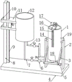
FIG. 1 is a schematic structural diagram of a test apparatus for measuring the rising height and rate of porous medium capillary water according to the present invention;
FIG. 2 is a schematic structural diagram of a test apparatus for measuring the capillary water elevation height and rate of porous media according to the present invention, which is shown in FIG. 1;
FIG. 3 is a schematic diagram of the cartridge of FIG. 2 in a test apparatus for measuring the capillary water elevation and rate of the porous medium according to the present invention;
FIG. 4 is a schematic structural diagram of an adjusting mechanism in FIG. 1 of a testing apparatus for measuring the capillary water lifting height and rate of porous media according to the present invention;
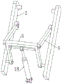
FIG. 5 is a schematic structural diagram of a testing apparatus for measuring the rising height and rate of porous medium capillary water according to the present invention, the driving mechanism in FIG. 1;
fig. 6 is a schematic diagram of the pipe connections among the water tank, the measuring cylinder and the experimental barrel in fig. 1 of the testing device for measuring the capillary water lifting height and rate of the porous medium.
In the figure: 1. an experiment barrel; 2. a support bar; 3. a transmission rod; 4. a base; 5. a gantry; 6. a measuring cylinder; 7. a drain pipe; 8. erecting a rod; 9. a rack; 10. a roller; 11. a support frame; 12. a water tank; 13. an overflow hose; 14. positioning a rod; 15. a slider; 16. a cross bar; 17. a reduction motor; 18. an electric push rod; 19. an air inlet pipe; 20. a first bevel gear; 21. a second bevel gear; 22. a rubber tube; 23. a limiting rod; 24. a sleeve; 25. a gear; 26. a box body; 27. an annular plate; 28. a humidity sensor; 29. a conduit; 30. a water seepage plate; 31. a grid plate; 32. a worm gear; 33. a rubber diaphragm; 34. a squeegee; 35. a second roller set; 36. a first roller train; 37. a worm.
Detailed Description
The technical solutions in the embodiments of the present invention will be clearly and completely described below with reference to the drawings in the embodiments of the present invention, and it is obvious that the described embodiments are only a part of the embodiments of the present invention, and not all of the embodiments. All other embodiments, which can be derived by a person skilled in the art from the embodiments given herein without making any creative effort, shall fall within the protection scope of the present invention.
Example 1:
referring to fig. 1-6, a test device for measuring the rising height and speed of porous medium capillary water comprises a base 4, a water tank 12, an experimental barrel 1 and a graduated cylinder 6, wherein the lower end of the water tank 12 is fixedly connected with a drain pipe 7 and an overflow hose 13, the lower end of the experimental barrel 1 is fixedly connected with a connecting pipe, one side of the experimental barrel 1 is fixedly connected with a water inlet pipe, the side wall of the graduated cylinder 6 is fixedly connected with one side of a support rod 2 through a connecting piece, the side wall of the graduated cylinder 6 is fixedly connected with a pipe orifice at one end of the overflow hose 13 through a water inlet hole, the other side of the graduated cylinder 6 is fixedly connected with a water outlet hose, one end of the water outlet hose is fixedly connected with the pipe orifice of the water inlet pipe, one end of the drain pipe 7 is fixedly connected with the pipe wall of the connecting pipe through a hose, the pipe walls of the drain pipe 7 and the overflow hose 13 are both connected with water valves, a rubber pipe 22 is arranged in the experimental barrel 1, the pipe orifices at the upper end and the lower end of the rubber pipe 22 are both fixedly connected with the inner wall of the experimental barrel 1, an air inlet pipe 19 is fixedly connected to one side of the experiment barrel 1, a cross rod 16 is arranged at the upper end of the experiment barrel 1, a feeding mechanism is connected to the rod wall of the cross rod 16 and is positioned in the experiment barrel 1, two support rods 2 are fixedly connected to the upper end of the base 4, a transmission mechanism is connected between the two support rods 2 and is connected with the side wall of the experiment barrel 1, the transmission mechanism comprises two transmission rods 3, one ends of the two transmission rods 3 are rotatably connected with the side wall of the experiment barrel 1 through rotating shafts, the upper end of the base 4 is rotatably connected with an electric push rod 18 through a shaft pin, one end of an output shaft of the electric push rod 18 is fixedly connected with a connecting block, one side of the connecting block is rotatably connected with a brake rod through a rolling bearing, two ends of the brake rod are fixedly connected with a portal frame 5 together, the side wall of the portal frame 5 is rotatably connected with the side wall of the support rods 2 through a rotating shaft, and a bent part of the portal frame 5 is rotatably connected with one end of the transmission rod 3 through a pin, experiment bucket 1 relative both sides all rotate with two bracing pieces 2 relative one sides respectively through the connecting axle and are connected, the upper end fixedly connected with pole setting 8 of base 4, be connected with adjustment mechanism on the pole wall of pole setting 8, adjustment mechanism is connected with the lateral wall of water tank 12, fixedly connected with grid plate 31 in the experiment bucket 1, the pipe wall fixed connection of round hole and pipe 29 is located at the center of grid plate 31, infiltration board 30 has been laid to the upper end of grid plate 31, and infiltration board 30 is the loop configuration, fixedly connected with rubber diaphragm 33 in the experiment bucket 1, the pipe wall fixed connection of mounting hole and pipe 29 is located at the center of rubber diaphragm 33.
When the device is used, firstly, a water-permeable sandstone layer is paved in an experiment barrel 1, then compressed gas is introduced from an air inlet pipe 19 to form a gap between a rubber pipe 22 and the experiment barrel 1, soil is placed in a feeding mechanism, the soil is put into the experiment barrel 1 by the feeding mechanism, the compressed gas is introduced again after paving is finished, the rubber pipe 22 extrudes the paved sample soil after being pressed to maintain the tightness, then the height of a water tank 12 is adjusted by an adjusting mechanism and experimental water is added, a water valve on an overflow hose 13 is opened, the experimental water enters the experiment barrel 1 through the overflow hose 13, when the liquid level in the experiment barrel 1 rises to a water seepage plate 30, the water valve is closed, the liquid level in a measuring cylinder 6 is at zero scale, then the water valve on a drain pipe 7 is opened, the experimental water in the drain pipe 7 enters the experiment barrel 1 through a water outlet hose, the liquid level stops rising when being blocked by the rubber diaphragm 33, because the liquid level in the water tank 12 has a height difference with the liquid level below the rubber diaphragm 33, the experimental water below the rubber diaphragm 33 has a certain water pressure, so that the pressure of underground water can be simulated, then the water valve is closed to keep the water pressure in the experimental barrel 1, and finally the rising data of capillary water is calculated by observing the data such as the liquid level height falling amount in the measuring cylinder 6 in unit time, so that the use of technical personnel is facilitated, when discharging is needed, firstly the feeding mechanism is taken down, then the air pressure in the interlayer between the rubber tube 22 and the experimental barrel 1 is discharged from the air inlet pipe 19, when the air pressure is reduced, the rubber tube 22 is elastically reset, so that the rubber tube 22 is separated from the sample soil, then the electric push rod 18 is started to retract to drive the stressed brake rod, when the brake rod is stressed, the portal frame 5 is driven to drive the transmission rod 3 to swing, when the transmission rod 3 swings, the experimental barrel 1 is driven to swing around the connection shaft, and then make experiment bucket 1 can incline, conveniently discharge its inside soil.
Example 2: the difference is based on example 1;
referring to fig. 2-3, the feeding mechanism includes a box 26, the box 26 is cylindrical, a sleeve 24 is fixedly connected to the center of the box 26 through a circular hole, the upper end of the sleeve 24 is rotatably connected to the rod wall of the cross bar 16 through a ball bearing, a guide tube 29 is sleeved in the sleeve 24, a plurality of humidity sensors 28 are fixedly connected to the tube wall of the guide tube 29, the lower end of the guide tube 29 is fixedly connected to the inner wall of the lower end of the experimental barrel 1, the lower end of the box 26 is rotatably connected to a first roller set 36 and a second roller set 35 through a bearing seat, a strip-shaped hole is formed in the side wall of the box 26, a reduction motor 17 is fixedly connected to the upper end of the cross bar 16, a first bevel gear 20 is fixedly connected to the output end of the reduction motor 17, a second bevel gear 21 is engaged to one side of the first bevel gear 20, the second bevel gear 21 is fixedly connected to the tube wall of the sleeve 24, and two positioning rods 14 are symmetrically and fixedly connected to the lower end of the cross bar 16, spacing spout has all been seted up on the pole wall of two locating levers 14, sliding connection has slider 15 in the spacing spout, slider 15 and experiment bucket 1's lateral wall fixed connection, box body 26's lower extreme fixedly connected with scraper blade 34, annular plate 27 has been cup jointed on sleeve pipe 24's the pipe wall, and rectangular through-hole has been seted up to annular plate 27's lateral wall, annular plate 27's lower extreme and box body 26's lower extreme inner wall contact, two gag lever posts 23 of upper end fixedly connected with of annular plate 27, the upper end of two gag lever posts 23 all with horizontal pole 16's lower extreme fixed connection.
The invention is provided with a feeding mechanism, when in use, the speed reducing motor 17 is started to drive the first bevel gear 20 to rotate the second bevel gear 21, the second bevel gear 21 rotates to drive the sleeve 24 to rotate the box body 26, the box body 26 rotates to drive the first roller group 36 and the second roller group 35 to do circular motion, therefore, when sample soil in the box body 26 is discharged from a strip-shaped hole, the sample soil is firstly scraped by the scraper 34 and then compacted by the first roller group 36 and the second roller group 35, further the compaction uniformity of the compacted sample soil is improved, the pressure comes from the self weight of the feeding mechanism, heavy objects can be pressed on the cross rod 16 according to requirements, when the thickness of the sample soil is increased, the first roller group 36 and the second roller group 35 can jack up the feeding mechanism, in addition, the annular plate 27 arranged in the box body 26 is fixed, therefore, when the box body 26 rotates for one week, the strip-shaped through hole is superposed with the rectangular through hole arranged on the annular plate 27 once, realize the interval ejection of compact, prevent to pile up too much sample soil and cause the soil compactness inhomogeneous.
Example 3: the difference is based on example 1;
referring to fig. 4, the adjusting mechanism includes a rack 9, a rack 9 is fixedly connected with a rod wall of a vertical rod 8, the rack 9 and the vertical rod 8 are connected with a support frame 11 in a sliding manner, the left end of the support frame 11 is connected with two rollers 10 through a support shaft in a rotating manner, the two rollers 10 are connected with one side of the support frame 11 in a rolling manner, the right end of the support frame 11 is fixedly connected with one side of a water tank 12, the side wall of the support frame 11 is connected with a transmission shaft through a first sealing bearing in a rotating manner, a worm wheel 32 and a gear 25 are fixedly connected onto the shaft wall of the transmission shaft, the gear 25 is meshed with the rack 9, a worm 37 is meshed with one side of the worm wheel 32, the rod wall of the worm 37 is connected with the side wall of the support frame 11 through a second sealing bearing in a rotating manner, and the lower end of the worm 37 passes through the second sealing bearing and is fixedly connected with a hand wheel.
The water pressure adjusting device is provided with the adjusting mechanism, when the water pressure adjusting device is used, a hand wheel is rotated to enable the worm 37 to rotate, the worm 37 rotates to drive the worm wheel 32 to enable the transmission shaft to rotate, the transmission shaft rotates to drive the gear 25 to rotate, the gear 25 rotates to roll on the rack 9, the rack 9 is fixed, therefore, the gear 25 is driven by the reverse force of the rack 9 to move, the transmission shaft moves to drive the support frame 11 to enable the water tank 12 to move, further, the water pressure in the experiment barrel 1 can be adjusted by changing the height of the water tank 12, and the water pressure adjusting device is convenient for technicians to use.
It is to be noted that the term "comprises," "comprising," or any other variation thereof is intended to cover a non-exclusive inclusion, such that a process, method, article, or apparatus that comprises a list of elements does not include only those elements but may include other elements not expressly listed or inherent to such process, method, article, or apparatus. Without further limitation, an element defined by the phrase "comprising an … …" does not exclude the presence of other identical elements in a process, method, article, or apparatus that comprises the element.
Although embodiments of the present invention have been shown and described, it will be appreciated by those skilled in the art that changes, modifications, substitutions and alterations can be made in these embodiments without departing from the principles and spirit of the invention, the scope of which is defined in the appended claims and their equivalents.
Claims (7)
1. The utility model provides a measure test device of porous medium capillary rising height and speed, includes base (4), water tank (12), experiment bucket (1) and graduated flask (6), the lower extreme fixedly connected with drain pipe (7) and overflow hose (13) of water tank (12), the lower extreme fixedly connected with connecting pipe of experiment bucket (1), one side fixedly connected with inlet tube, its characterized in that of experiment bucket (1): be equipped with rubber tube (22) in experiment bucket (1), the upper and lower both ends mouth of pipe department of rubber tube (22) all with the inner wall fixed connection of experiment bucket (1), one side fixedly connected with intake pipe (19) of experiment bucket (1), the upper end of experiment bucket (1) is equipped with horizontal pole (16), be connected with feed mechanism on the pole wall of horizontal pole (16), feed mechanism is located experiment bucket (1), two bracing pieces of upper end fixedly connected with (2) of base (4), two be connected with drive mechanism between bracing piece (2), drive mechanism is connected with the lateral wall of experiment bucket (1), the upper end fixedly connected with pole setting (8) of base (4), be connected with adjustment mechanism on the pole wall of pole setting (8), adjustment mechanism is connected with the lateral wall of water tank (12).
2. The test device for measuring the capillary water lifting height and rate of the porous medium according to claim 1, wherein: the feeding mechanism comprises a box body (26), the box body (26) is cylindrical, a sleeve (24) is fixedly connected to the center of the box body (26) through a round hole, the upper end of the sleeve (24) is rotatably connected with the rod wall of the cross rod (16) through a ball bearing, a guide pipe (29) is sleeved in the sleeve (24), a plurality of humidity sensors (28) which are uniformly distributed are fixedly connected to the pipe wall of the guide pipe (29), the lower end of the guide pipe (29) is fixedly connected with the inner wall of the lower end of the experimental barrel (1), the lower end of the box body (26) is respectively rotatably connected with a first roller set (36) and a second roller set (35) through a bearing seat, a strip-shaped hole is formed in the side wall of the box body (26), a speed reducing motor (17) is fixedly connected to the upper end of the cross rod (16), and a first bevel gear (20) is fixedly connected to the output end of the speed reducing motor (17), one side of the first bevel gear (20) is engaged with a second bevel gear (21), the second bevel gear (21) is fixedly connected with the pipe wall of the sleeve (24), the lower end of the transverse rod (16) is symmetrically and fixedly connected with two positioning rods (14), limiting sliding grooves are formed in the rod walls of the two positioning rods (14), sliding blocks (15) are connected in the limiting sliding grooves in a sliding mode, and the sliding blocks (15) are fixedly connected with the side wall of the experiment barrel (1).
3. The test device for measuring the capillary water lifting height and rate of the porous medium according to claim 2, wherein: the lower extreme fixedly connected with scraper blade (34) of box body (26), annular plate (27) have been cup jointed on the pipe wall of sleeve pipe (24), and the rectangle through-hole has been seted up to the lateral wall of annular plate (27), the lower extreme of annular plate (27) and the lower extreme inner wall contact of box body (26), two gag lever posts (23), two of the upper end fixedly connected with of annular plate (27) the upper end of gag lever post (23) all with the lower extreme fixed connection of horizontal pole (16).
4. The test device for measuring the capillary water lifting height and rate of the porous medium according to claim 1, wherein: drive mechanism includes two transfer lines (3), two the one end of transfer line (3) all rotates through the pivot and is connected with the lateral wall of experiment bucket (1), the upper end of base (4) is rotated through the pivot and is connected with electric putter (18), the output shaft one end fixedly connected with connecting block of electric putter (18), one side of connecting block rotates through antifriction bearing and is connected with the brake lever, common fixedly connected with portal frame (5) in both ends of brake lever, the lateral wall of portal frame (5) is passed through the rotation axis and is connected with the lateral wall rotation of bracing piece (2), the department of buckling of portal frame (5) is rotated through the one end of pin with transfer line (3) and is connected, experiment bucket (1) relative both sides all rotate with two bracing pieces (2) relative one side respectively through the connecting axle and are connected.
5. The test device for measuring the capillary water lifting height and rate of the porous medium according to claim 1, wherein: the adjusting mechanism comprises a rack (9), the rack (9) is fixedly connected with the rod wall of the vertical rod (8), the rack (9) and the vertical rod (8) are connected with a support frame (11) in a sliding mode, the left end of the support frame (11) is rotatably connected with two rollers (10) through a support shaft, the rollers (10) are respectively in rolling connection with one side of the support frame (11), the right end of the support frame (11) is fixedly connected with one side of a water tank (12), the side wall of the support frame (11) is rotatably connected with a transmission shaft through a first sealing bearing, a worm wheel (32) and a gear (25) are fixedly connected onto the shaft wall of the transmission shaft, the gear (25) is meshed with the rack (9), a worm (37) is meshed with one side of the worm wheel (32), and the rod wall of the worm (37) is rotatably connected with the side wall of the support frame (11) through a second sealing bearing, the lower end of the worm (37) penetrates through the second sealing bearing and is fixedly connected with a hand wheel.
6. The test device for measuring the capillary water lifting height and rate of the porous medium according to claim 1, wherein: fixedly connected with net board (31) in experiment bucket (1), the pipe wall fixed connection through round hole and pipe (29) is located at the center of net board (31), infiltration board (30) have been laid to the upper end of net board (31), and infiltration board (30) are the loop configuration, fixedly connected with rubber diaphragm (33) in experiment bucket (1), the pipe wall fixed connection through mounting hole and pipe (29) is located at the center of rubber diaphragm (33).
7. The test device for measuring the capillary water lifting height and rate of the porous medium according to claim 1, wherein: the lateral wall of graduated flask (6) passes through the one side fixed connection of connecting piece and bracing piece (2), the lateral wall of graduated flask (6) passes through the one end mouth of pipe department fixed connection of inlet opening and overflow hose (13), the opposite side fixedly connected with of graduated flask (6) goes out the water hose, the one end of going out the water hose and the mouth of pipe department fixed connection of inlet tube, the pipe wall fixed connection of hose and connecting pipe is passed through to the one end of drain pipe (7), all be connected with the water valve on the pipe wall of drain pipe (7) and overflow hose (13).
Priority Applications (1)
| Application Number | Priority Date | Filing Date | Title |
|---|---|---|---|
| CN202111219065.1A CN114047100B (en) | 2021-10-20 | 2021-10-20 | Test device for measuring capillary water elevation and capillary water velocity of porous medium |
Applications Claiming Priority (1)
| Application Number | Priority Date | Filing Date | Title |
|---|---|---|---|
| CN202111219065.1A CN114047100B (en) | 2021-10-20 | 2021-10-20 | Test device for measuring capillary water elevation and capillary water velocity of porous medium |
Publications (2)
| Publication Number | Publication Date |
|---|---|
| CN114047100A true CN114047100A (en) | 2022-02-15 |
| CN114047100B CN114047100B (en) | 2023-12-15 |
Family
ID=80205564
Family Applications (1)
| Application Number | Title | Priority Date | Filing Date |
|---|---|---|---|
| CN202111219065.1A Active CN114047100B (en) | 2021-10-20 | 2021-10-20 | Test device for measuring capillary water elevation and capillary water velocity of porous medium |
Country Status (1)
| Country | Link |
|---|---|
| CN (1) | CN114047100B (en) |
Citations (20)
| Publication number | Priority date | Publication date | Assignee | Title |
|---|---|---|---|---|
| US5644947A (en) * | 1995-01-19 | 1997-07-08 | Lockheed Idaho Technologies Company | Tensiometer and method of determining soil moisture potential in below-grade earthen soil |
| AU6983598A (en) * | 1994-11-23 | 1998-10-01 | Kimberly-Clark Worldwide, Inc. | Capillary dewatering method and apparatus |
| JP2003094035A (en) * | 2001-09-27 | 2003-04-02 | Mitsubishi Heavy Ind Ltd | Purifying apparatus for contaminated soil |
| KR20060108414A (en) * | 2005-04-13 | 2006-10-18 | (주)지구환경전문가그룹 | Test apparatus of draining ability |
| CN102680377A (en) * | 2012-06-06 | 2012-09-19 | 中国科学院地质与地球物理研究所 | Test device for measuring rising heights and speeds of porous medium capillary water |
| CN104049073A (en) * | 2014-06-18 | 2014-09-17 | 中国科学院武汉岩土力学研究所 | Compacted clay impervious structure cracking failure simulation test system under environmental gradient action |
| CN204903309U (en) * | 2015-09-02 | 2015-12-23 | 湖南省水利水电科学研究所 | Soil cement seepage deformation testing arrangement |
| CN205138969U (en) * | 2015-10-30 | 2016-04-06 | 长春工程学院 | Test device of semi -automatization soil capillary rising degree on water and speed |
| US20160185174A1 (en) * | 2014-12-31 | 2016-06-30 | Ge Energy Oilfield Technology, Inc. | Trailer and Chassis Design for Mobile Core Scanning System |
| US20160223450A1 (en) * | 2013-04-22 | 2016-08-04 | Empresa Brasileira De Pesquisa Agropecuaria - Embrapa | Water tension sensor, system for characterising and continuously measuring soil water, system for indicating critical soil water tension and irrigation rod |
| CN106996970A (en) * | 2017-04-26 | 2017-08-01 | 长沙理工大学 | A kind of unsaturated soil nonlinear strength envelope shell model |
| CN107247131A (en) * | 2017-07-28 | 2017-10-13 | 长沙理工大学 | Rock expansion rate tester capable of controlling temperature and automatically replenishing water |
| CN207439877U (en) * | 2017-11-24 | 2018-06-01 | 天津科信建设工程检测有限公司 | A kind of permeameter |
| CN109682948A (en) * | 2019-01-29 | 2019-04-26 | 南昌工程学院 | A kind of imitative experimental appliance and its experimental method of charcoal improvement red soil |
| CN209167305U (en) * | 2018-11-21 | 2019-07-26 | 郑州大学 | A kind of full-automatic constant head Seep- Solidifying cross matching device |
| CN110441218A (en) * | 2019-08-30 | 2019-11-12 | 海南方能测试技术有限公司 | A kind of concrete permeable detection device and detection method |
| US20200018681A1 (en) * | 2019-08-02 | 2020-01-16 | Southwest Petroleum University | Irregular rock sample high-pressure permeation device with adjustable flow direction and test method thereof |
| CN211856276U (en) * | 2019-11-28 | 2020-11-03 | 郑州大学 | Novel full-automatic control by temperature change consolidation infiltration cross test device |
| WO2021042327A1 (en) * | 2019-09-05 | 2021-03-11 | 浙江大学 | Test device capable of simulating the erosion effect and interface shear of suction bucket foundation installation, and test method |
| CN112986103A (en) * | 2021-05-06 | 2021-06-18 | 深圳市天地新材料有限公司 | Concrete water permeability coefficient detection device |
-
2021
- 2021-10-20 CN CN202111219065.1A patent/CN114047100B/en active Active
Patent Citations (20)
| Publication number | Priority date | Publication date | Assignee | Title |
|---|---|---|---|---|
| AU6983598A (en) * | 1994-11-23 | 1998-10-01 | Kimberly-Clark Worldwide, Inc. | Capillary dewatering method and apparatus |
| US5644947A (en) * | 1995-01-19 | 1997-07-08 | Lockheed Idaho Technologies Company | Tensiometer and method of determining soil moisture potential in below-grade earthen soil |
| JP2003094035A (en) * | 2001-09-27 | 2003-04-02 | Mitsubishi Heavy Ind Ltd | Purifying apparatus for contaminated soil |
| KR20060108414A (en) * | 2005-04-13 | 2006-10-18 | (주)지구환경전문가그룹 | Test apparatus of draining ability |
| CN102680377A (en) * | 2012-06-06 | 2012-09-19 | 中国科学院地质与地球物理研究所 | Test device for measuring rising heights and speeds of porous medium capillary water |
| US20160223450A1 (en) * | 2013-04-22 | 2016-08-04 | Empresa Brasileira De Pesquisa Agropecuaria - Embrapa | Water tension sensor, system for characterising and continuously measuring soil water, system for indicating critical soil water tension and irrigation rod |
| CN104049073A (en) * | 2014-06-18 | 2014-09-17 | 中国科学院武汉岩土力学研究所 | Compacted clay impervious structure cracking failure simulation test system under environmental gradient action |
| US20160185174A1 (en) * | 2014-12-31 | 2016-06-30 | Ge Energy Oilfield Technology, Inc. | Trailer and Chassis Design for Mobile Core Scanning System |
| CN204903309U (en) * | 2015-09-02 | 2015-12-23 | 湖南省水利水电科学研究所 | Soil cement seepage deformation testing arrangement |
| CN205138969U (en) * | 2015-10-30 | 2016-04-06 | 长春工程学院 | Test device of semi -automatization soil capillary rising degree on water and speed |
| CN106996970A (en) * | 2017-04-26 | 2017-08-01 | 长沙理工大学 | A kind of unsaturated soil nonlinear strength envelope shell model |
| CN107247131A (en) * | 2017-07-28 | 2017-10-13 | 长沙理工大学 | Rock expansion rate tester capable of controlling temperature and automatically replenishing water |
| CN207439877U (en) * | 2017-11-24 | 2018-06-01 | 天津科信建设工程检测有限公司 | A kind of permeameter |
| CN209167305U (en) * | 2018-11-21 | 2019-07-26 | 郑州大学 | A kind of full-automatic constant head Seep- Solidifying cross matching device |
| CN109682948A (en) * | 2019-01-29 | 2019-04-26 | 南昌工程学院 | A kind of imitative experimental appliance and its experimental method of charcoal improvement red soil |
| US20200018681A1 (en) * | 2019-08-02 | 2020-01-16 | Southwest Petroleum University | Irregular rock sample high-pressure permeation device with adjustable flow direction and test method thereof |
| CN110441218A (en) * | 2019-08-30 | 2019-11-12 | 海南方能测试技术有限公司 | A kind of concrete permeable detection device and detection method |
| WO2021042327A1 (en) * | 2019-09-05 | 2021-03-11 | 浙江大学 | Test device capable of simulating the erosion effect and interface shear of suction bucket foundation installation, and test method |
| CN211856276U (en) * | 2019-11-28 | 2020-11-03 | 郑州大学 | Novel full-automatic control by temperature change consolidation infiltration cross test device |
| CN112986103A (en) * | 2021-05-06 | 2021-06-18 | 深圳市天地新材料有限公司 | Concrete water permeability coefficient detection device |
Non-Patent Citations (5)
| Title |
|---|
| JOHN C. STORMONT 等: "Capillary Barrier Effect from Underlying Coarser Soil Layer", 《JOURNAL OF GEOTECHNICAL AND GEOENVIRONMENTAL ENGINEERING》, no. 8, pages 641 * |
| YONGAN GU 等: "A novel contact angle measurement technique by analysis of capillary rise profile around a cylinder (ACRPAC)", 《COLLOIDS AND SURFACES A: PHYSICOCHEMICAL AND ENGINEERING ASPECTS》, vol. 122, no. 1, pages 135 - 149, XP086197391, DOI: 10.1016/S0927-7757(96)03853-8 * |
| ZHIMING HU 等: "Optocapillarity-driven assembly and reconfiguration of liquid crystal polymer actuators", 《NATURE COMMUNICATIONS》, vol. 11, pages 5780 * |
| 余敦猛 等: "武广客专红粘土变形特性及形成机理研究", 《武汉理工大学学报(交通科学与工程版)》, vol. 34, no. 6, pages 1255 - 1259 * |
| 王龙飞: "综采工作面煤层注水渗流模型及防突机理研究与应用", 《中国博士学位论文全文数据库工程科技Ⅰ辑》, no. 8, pages 021 - 18 * |
Also Published As
| Publication number | Publication date |
|---|---|
| CN114047100B (en) | 2023-12-15 |
Similar Documents
| Publication | Publication Date | Title |
|---|---|---|
| US10823720B2 (en) | Deep soil water percolation monitor and monitoring method therefor | |
| CN109870398B (en) | Penetration test system | |
| CN201130143Y (en) | Porous medium material permeability coefficient determinator | |
| CN111337650B (en) | Multifunctional test device for researching seepage damage mechanism of underground engineering soil body | |
| CN109682744B (en) | Test device and method for evaluating permeable asphalt pavement gap evolution rule | |
| CN210322721U (en) | Water-permeable paving material blocking rule testing device | |
| CN108332816B (en) | Device and method for measuring exchange water quantity of surface water and underground water of river channel | |
| CN105651677A (en) | Geotechnical parameter and property tester capable of simultaneously testing specific yield and osmotic coefficient | |
| CN104655468B (en) | Sample preparation device and sample preparation method for sand-soil contact surface test sample as well as osmotic coefficient determination method | |
| CN111551691A (en) | Multifunctional side slope model test device | |
| CN111272634A (en) | Permeable pavement permeability coefficient on-site measurement device and method | |
| CN105675471A (en) | Multi-angle diameter-variable type Darcy seepage experiment device | |
| CN217586826U (en) | Accurate test system of multiclass soil horizontal permeability coefficient | |
| CN115165702A (en) | Large-size soil body permeability test device and method capable of adjusting water head and seepage direction | |
| CN116519409A (en) | Coarse-grained soil sample preparation device and method for simulating seepage-erosion and measuring soil-water characteristics | |
| CN211292478U (en) | Railway roadbed graded broken stone permeability coefficient and permeability deformation measurement test device | |
| CN113552037B (en) | Device and method for testing dual-porosity seepage parameters of garbage | |
| CN114047100A (en) | Test device for measuring rising height and rate of porous medium capillary water | |
| CN113959925A (en) | Ecological water permeable pavement work simulation device and simulation method | |
| CN211374440U (en) | Integrated soil infiltration rate measuring combined device | |
| CN114279934B (en) | Island reef water-rich calcareous sandy soil stratum grouting simulation and permeability test device and method | |
| CN210180880U (en) | Penetration test system | |
| CN106248558B (en) | Compacting soil doped with large-particle-size rubber sheet permeability coefficient testing device and method | |
| Ajdari et al. | Experimental evaluation of the influence of the level of the ground water table on the bearing capacity of circular footings | |
| CN214278155U (en) | Sample deformation testing arrangement that absorbs water |
Legal Events
| Date | Code | Title | Description |
|---|---|---|---|
| PB01 | Publication | ||
| PB01 | Publication | ||
| SE01 | Entry into force of request for substantive examination | ||
| SE01 | Entry into force of request for substantive examination | ||
| GR01 | Patent grant | ||
| GR01 | Patent grant |