Disclosure of Invention
In view of the above-mentioned drawbacks, the present invention provides a liquid metering device, which has a simple structure, is convenient to use, can effectively improve the accuracy of liquid metering, and has low cost and high metering speed.
In order to achieve the purpose, the invention provides a liquid metering device which comprises a liquid storage tank, wherein a metering cylinder is arranged in the liquid storage tank, the bottom of the metering cylinder is communicated with a supporting rod, a sealing gasket is fixedly connected to the periphery of the joint of the supporting rod and the metering cylinder, a guide sealing sleeve is fixedly connected to the outer bottom of the liquid storage tank, the bottom end of the supporting rod extends out of the liquid storage tank and penetrates through the guide sealing sleeve to be rotatably connected with one end of a lever, the bottom of the other end of the lever is rotatably connected with a vertically arranged connecting rod, the bottom of the connecting rod is slidably connected with an adjusting component, and a fulcrum component is arranged at the bottom of the lever; a water pipe is arranged in the support rod and comprises a vertical section communicated with the metering cylinder and a horizontal section communicated with the vertical section, an accommodating space is formed in the middle of one side of the guide sealing sleeve, and the horizontal section extends out of the accommodating space; the adjusting assembly comprises an extensible member, an output shaft of the extensible member is fixedly connected with a wedge block, the inclined surface of the wedge block is connected with the connecting rod in a sliding mode, the middle of the connecting rod is sleeved with a limiting piece, and when the connecting rod is located at the highest position of the wedge block, the lever is in a horizontal state; the fulcrum assembly comprises an adjusting rod which is vertically arranged, the bottom of the adjusting rod is slidably connected to the base, a lead screw penetrates through the middle of the adjusting rod, two ends of the lead screw are rotatably connected to two side walls of the base, one end of the lead screw penetrates through the side wall of the base and then is fixedly connected with a motor, the motor is fixedly connected to the side wall of the base, a forward rotation switch and a reverse rotation switch are arranged on the motor, and when the wedge block extends out under the driving of the telescopic piece, the wedge block can press the forward rotation switch; the top of the vertical section is provided with an electromagnetic valve, and the electromagnetic valve is electrically connected with an electromagnetic valve controller.
According to the liquid metering device, the inclined surface of the wedge block is provided with a limiting groove, the limiting groove is connected with a first roller in a sliding mode, the first roller is limited in the limiting groove, and the upper portion of the first roller is fixedly connected with the connecting rod.
According to the liquid metering device, the electromagnetic valve controller is positioned at the bottom of the limiting groove.
According to the liquid metering device, the second roller is arranged at the top of the adjusting rod, the sliding rail is arranged at the bottom of the lever, and the second roller is located in the sliding rail.
According to the liquid metering device, the limiting part comprises a limiting block sleeved on the connecting rod, one side of the limiting block is fixedly connected with the horizontal rod, and the other end of the horizontal rod is fixedly connected with the supporting table.
According to the liquid metering device, the bottom of the adjusting rod is provided with the sliding block, and the base is provided with the sliding groove matched with the sliding block.
According to the liquid metering device, the telescopic piece is an electric cylinder.
The invention aims to provide a liquid metering device, which can ensure that a lever is in a horizontal state after being rotated and reset every time and a metering cylinder can be positioned below a liquid level to contain liquid by arranging an adjusting component, and the adjusting component can also be in linkage work with a motor and an electromagnetic valve to ensure that the device runs stably; through setting up the fulcrum subassembly, can realize when the connecting rod drives the one end decline same height of lever, the position that the fulcrum subassembly is located the lever is different, and the one end that the lever is connected with the bracing piece is high different that rises, descends gradually along with the liquid level in the liquid reserve tank, can make the height that the measuring cylinder rises descend gradually promptly, had both guaranteed the liquid precision in the measuring cylinder at every turn like this, also can shorten the stroke of measuring cylinder, reduces the measuring time and improves the measurement speed. In conclusion, the beneficial effects of the invention are as follows: the metering precision is high, the cost is low, and the metering speed is high.
Detailed Description
In order to make the objects, technical solutions and advantages of the present invention more apparent, the present invention is further described in detail below with reference to the accompanying drawings. It should be understood that the specific embodiments described herein are merely illustrative of the invention and are not intended to limit the invention.
It should be noted that in the description of the present invention, the terms of direction or positional relationship indicated by the terms "upper", "lower", "left", "right", "inner", "outer", etc. are based on the directions or positional relationships shown in the drawings, which are only for convenience of description, and do not indicate or imply that the device or element must have a specific orientation, be constructed in a specific orientation, and be operated, and thus, should not be construed as limiting the present invention.
Furthermore, it should be noted that, in the description of the present invention, unless otherwise explicitly specified or limited, the terms "mounted," "connected," and "connected" are to be construed broadly, and may be, for example, fixedly connected, detachably connected, or integrally connected; can be mechanically or electrically connected; they may be connected directly or indirectly through intervening media, or they may be interconnected between two elements. The specific meanings of the above terms in the present invention can be understood by those skilled in the art according to specific situations.
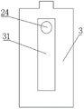
Referring to fig. 1 and 3, the invention provides a liquid metering device, which comprises a liquid storage tank 1, wherein a metering cylinder 21 is arranged in the liquid storage tank 1, the bottom of the metering cylinder 21 is communicated with a support rod 23, a sealing gasket 22 is fixedly connected to the periphery of the joint of the support rod 23 and the metering cylinder 21, and the sealing gasket 22 seals the support rod 23 and the metering cylinder 21 on one hand and can provide buffer for the metering cylinder 21 on the other hand so as to prevent the bottom of the metering cylinder 21 from colliding with the liquid storage tank 1; with reference to fig. 4, the outer bottom of the liquid storage tank 1 is fixedly connected with a guide sealing sleeve 3, the bottom end of the support rod 23 extends out of the liquid storage tank 1 and penetrates through the guide sealing sleeve 3 to be rotatably connected with one end of the lever 4, the guide sealing sleeve 3 can seal the joint of the support rod 23 and the liquid storage tank 1 and can also provide guide for the up-and-down movement of the support rod 23, so that the support rod 23 can vertically move up and down, the metering cylinder 21 is ensured to be always in a horizontal state, and the liquid measuring accuracy is improved; the connecting rod 42 of vertical setting is connected in the rotation of the other end bottom of lever 4, and the bottom sliding connection adjusting part of connecting rod 42, the bottom of lever 4 are equipped with the fulcrum subassembly, and adjusting part can drive lever 4 and rotate under the support of fulcrum subassembly, and then drive bracing piece 23 and reciprocate.
The inside water pipe 24 that is equipped with of bracing piece 23, water pipe 24 include with the vertical section that a measuring section of thick bamboo 21 link up and with the horizontal segment that vertical section link up, one side middle part of direction seal cover 3 is equipped with accommodation space 31, the horizontal segment stretches out from accommodation space 31, accommodation space 31 provides the space for the horizontal segment when bracing piece 23 drives water pipe 24 and reciprocates.
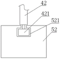
Combine fig. 6, the adjusting part includes extensible member 51, rigid coupling voussoir 52 on extensible member 51's the output shaft, extensible member 51 can drive voussoir 52 round trip movement, sliding connection connecting rod 42 on voussoir 52's the inclined plane, during voussoir 52 round trip movement, connecting rod 42 reciprocates along voussoir 52's inclined plane, locating part 53 is cup jointed at the middle part of connecting rod 42, locating part 53 is including cup jointing the stopper on connecting rod 42, one side rigid coupling horizon bar of stopper, the other end rigid coupling brace table of horizon bar, the brace table is fixed motionless, locating part 53 can make connecting rod 42 reciprocate but can not control about. It should be noted that, when the connecting rod 42 is located at the highest position of the wedge block 52, the lever 4 is located in a horizontal state, at this time, the supporting rod 23 drives the measuring cylinder 21 to be located at the bottom of the liquid storage tank 1, and when the connecting rod 42 reaches the lowest position of the wedge block 52, the lever 4 drives the supporting rod 23 to upwards enable the measuring cylinder 21 to upwards extend out of the liquid level of the liquid storage tank 1, namely, the measuring cylinder 21 is full of liquid and then extends out of the liquid level, and because the measuring cylinder 21 is full at every time, the accuracy of the measured liquid is high.
Preferably, the telescopic member 51 is an electric cylinder.
Referring to fig. 7, in order to keep the connecting rod 42 and the inclined surface of the wedge 52 in a connected state and make the connecting rod 42 run more smoothly, a limiting groove 521 is formed on the inclined surface of the wedge, a first roller 421 is slidably connected in the limiting groove 521, the first roller 421 is limited in the limiting groove 521, and the upper part of the first roller 421 is fixedly connected with the connecting rod 42. Because the connecting rod 42 is connected with one end of the lever 4 in a rotating manner, when the connecting rod 42 moves up and down, one end of the lever 4 can be driven to ascend or descend, and because the other end of the lever 4 is connected with the supporting rod 23 in a rotating manner, the supporting rod 23 moves up and down under the driving of the lever 4 under the supporting of the fulcrum assembly.
Referring to fig. 5, the fulcrum assembly includes an adjusting rod 61 vertically disposed, a second roller 62 is disposed on the top of the adjusting rod 61, the top of the second roller 62 abuts against the bottom of the lever 4, the second roller 62 can reduce friction between the adjusting rod 61 and the lever 4, the bottom of the adjusting rod 61 is slidably connected to a base 64, a lead screw 63 is disposed in the middle of the adjusting rod 61, two ends of the lead screw 63 are rotatably connected to two side walls of the base 64, one end of the lead screw 63 penetrates through a side wall of the base 64 and is fixedly connected to a motor 65, the motor 65 is fixedly connected to a side wall of the base 64, a forward rotation switch 651 and a reverse rotation switch (not shown) are disposed on the motor 65, when the wedge 52 extends out under the driving of the extensible member 51, the wedge 52 can press the forward rotation switch 651, so that the motor 65 is turned on, the motor 65 drives the lead screw 63 to rotate, the lead screw 63 rotates to drive the adjusting rod 61 to move, when the extensible member 51 resets, the motor 65 stops rotating, and the adjusting rod 61 stops, that is, whenever the lever 4 is in a horizontal state, the motor 65 drives the adjusting rod 61 to move a certain distance, and the lever 4 in the horizontal state facilitates the movement of the adjusting rod 61.
Further, the bottom of the lever 4 is provided with a slide rail 41, the second roller 62 is located in the slide rail 41, and the second roller 62 is matched with the slide rail 41, so that the device can run more stably.
The adjusting rod 61 moves along the lever 4, namely, the position of the supporting point component on the supporting lever 4 can be adjusted, so that the effect that when the connecting rod 42 drives one end of the lever 4 to descend to the same height can be realized, the position of the supporting point component on the lever 4 is different, the rising height of one end of the lever 4 connected with the supporting rod 23 is different, concretely, when the supporting point component is close to the wedge block 52, when the connecting rod 42 drives one end of the lever 4 to descend to the same height, the rising height of one end of the lever 4 connected with the supporting rod 23 is the highest, the highest position is reached when the measuring cylinder 21 rises at the moment, when the supporting point component is close to the supporting rod 23, the connecting rod 42 drives one end of the lever 4 to descend to the same height, the rising height of one end of the lever 4 connected with the supporting rod 23 is the lowest, and the lowest position is reached when the measuring cylinder 21 rises at the moment.
Furthermore, the bottom of the adjusting rod 61 is provided with a sliding block 611, the base 64 is provided with a sliding groove 641 matched with the sliding block 611, the adjusting rod 61 drives the sliding block 611 to slide in the sliding groove 641, on one hand, the adjusting rod 61 is prevented from rotating along with the screw rod 63, on the other hand, the supporting force of the adjusting rod 61 is improved, and the adjusting rod 61 is prevented from shaking when the lever 4 rotates.
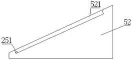
The solenoid valve 25 is arranged at the top of the vertical section of the water pipe 24, the solenoid valve 25 is electrically connected with the solenoid valve controller 251, the solenoid valve 25 is controlled to be opened and closed through the solenoid valve controller 251, the solenoid valve controller 251 is positioned at the bottom of the limiting groove 521, the wedge block 52 is driven to contract when the telescopic piece 51 contracts, the connecting rod 42 is positioned at the bottom of the limiting groove 521 to press the solenoid valve controller 251, the solenoid valve 25 is opened, the supporting rod 23 drives the metering cylinder 21 to move upwards at the moment, the metering cylinder 21 is positioned on the liquid level in the liquid storage tank 1, so quantitative liquid is contained in the metering cylinder 21, and after the solenoid valve 25 is opened, the liquid flows out of the metering cylinder 21 through the water pipe 24.
The working principle of the invention is as follows:
at the initial state, the expansion piece 51 is in the expansion state, but does not abut against the motor 65, the connecting rod 42 is close to the highest end of the wedge block 52, at this time, the lever 4 is close to the horizontal state, the adjusting rod 61 is located at one end close to the wedge block 52, the metering cylinder 21 is located below the liquid level of the liquid in the liquid storage tank 1, at this time, the metering cylinder 21 is filled with the liquid, the expansion piece 51 contracts, the wedge block 52 is paused after contracting, the connecting rod 42 is located at the lowest end of the wedge block 52, at this time, the lever 4 drives the supporting rod 23 to move upwards, so that the metering cylinder 21 extends out of the liquid level of the liquid in the liquid storage tank 1, at this time, the metering cylinder 21 can measure accurate liquid, at the same time, the electromagnetic valve controller 251 is pressed, the electromagnetic valve 25 is controlled to be opened, the liquid in the metering cylinder 21 flows out through the water pipe 24, after the liquid completely flows out, the expansion piece 51 expands, the connecting rod 42 leaves the electromagnetic valve controller 251, the electromagnetic valve 25 is closed, the connecting rod 42 is located at the highest end of the wedge block 52, the lever 4 is in a horizontal state, the metering cylinder 21 is located below the liquid level in the liquid storage tank 1 to fill liquid again, meanwhile, the wedge block 52 abuts against the forward rotation switch 651, the motor 65 drives the screw rod 63 to rotate, the adjusting rod 61 moves towards the direction of the supporting rod 23, after the metering cylinder 21 is filled, the telescopic piece 51 contracts again, the wedge block 52 leaves the forward rotation switch 651, the screw rod 63 stops rotating, the adjusting rod 61 stops moving, the connecting rod 42 is located at the lowest end of the wedge block 52, at the moment, the lever 4 drives the supporting rod 23 to move upwards to enable the metering cylinder 21 to extend out of the liquid level in the liquid storage tank 1, as the adjusting rod 61 moves a certain distance towards the supporting rod 23, the fulcrum of the lever 4 changes, the ascending height of the metering cylinder 21 at this time is lower than the ascending height at the last time, and the liquid level in the liquid storage tank descends after the last measured liquid is discharged, therefore, even if the ascending height of the metering cylinder 21 is lower than the ascending height of the last time, the metering cylinder 21 can extend out of the liquid level of the liquid storage tank, and the metering cylinder 21 can measure a certain amount of liquid, so that the running time of the metering cylinder 21 can be reduced, and the measuring speed can be improved; meanwhile, the electromagnetic valve controller 251 is pressed, the electromagnetic valve 25 is controlled to be opened, the liquid in the metering cylinder 21 flows out through the water pipe 24, the operation is sequentially performed, when the adjusting rod 61 moves to one end close to the supporting rod 23, the liquid in the liquid storage tank 1 is nearly exhausted, the metering cylinder 21 cannot be filled, at the moment, new liquid is added into the liquid storage tank 1, the reversing switch of the motor 65 is turned on, the adjusting rod 61 is enabled to return to one end of the wedge block 52, and the measuring is performed again.
In conclusion, the adjusting assembly is arranged, so that the lever can be ensured to be in a horizontal state after being rotated and reset every time, the metering cylinder can be ensured to be positioned below the liquid level to contain liquid, the adjusting assembly can also be in linkage work with the motor and the electromagnetic valve, and the stable operation of the device is ensured; through setting up the fulcrum subassembly, can realize when the connecting rod drives the one end decline same height of lever, the position that the fulcrum subassembly is located the lever is different, and the one end that the lever is connected with the bracing piece is high different that rises, descends gradually along with the liquid level in the liquid reserve tank, can make the height that the measuring cylinder rises descend gradually promptly, had both guaranteed the liquid precision in the measuring cylinder at every turn like this, also can shorten the stroke of measuring cylinder, reduces the measuring time and improves the measurement speed. The invention has the beneficial effects that: the metering precision is high, the cost is low, and the metering speed is high.
The present invention may be embodied in other specific forms without departing from the spirit or essential attributes thereof, and it should be understood that various changes and modifications can be effected therein by one skilled in the art without departing from the spirit and scope of the invention as defined in the appended claims.