Municipal domestic waste drying device and using method thereof
Technical Field
The invention belongs to the technical field of garbage drying treatment, and particularly relates to a municipal domestic garbage drying device and a using method thereof.
Background
The municipal solid waste is waste generated in daily life of people, if the municipal solid waste can not be reasonably treated, the living environment of human beings can be seriously threatened, the incineration energy and the low-temperature pyrolysis are effective means for carrying out harmless and resource treatment on the municipal solid waste, however, the municipal solid waste has high moisture, which is very unfavorable for subsequent incineration and pyrolysis, so that the dehydration and drying (namely drying) of the municipal solid waste are imperative.
At present, the most common drying mode is to blow dry hot air into the position where the garbage is located for accelerating the evaporation and loss of water in the garbage, and when drying is carried out, the main placing modes of the garbage include the following two modes:
a: the method has the advantages that the garbage is stacked in the drying box, the method has the defects that the surface layer garbage drying speed is high, but the garbage on the inner layer can be dried for a long time to remove moisture, and the method has the advantages of high laying speed and low labor cost;
b: the garbage is paved on the layered frame plate, and the method has the advantages of high drying speed; the defects are that the laying steps are complicated, the labor cost is high, the occupied space of the equipment is large, the quantity of the goods which can be dried by the equipment at one time is small, and the overall efficiency is not high.
Based on the advantages and disadvantages and working steps of the two paving modes, the invention provides the municipal domestic waste drying device which can directly dump the waste on the dynamic fork frame and has the advantages of the two paving modes and the use method thereof.
Disclosure of Invention
In view of the above situation, in order to overcome the defects of the prior art, the invention provides a drying device and a using method thereof, wherein the drying device is used for drying household garbage such as kitchen garbage and the like, and can slowly and continuously pick up the garbage in an unpowered manner in the drying process so as to enable hot air to flow through the household garbage; because the household garbage is relatively fine and broken, if the household garbage is placed on the fixed inclined fork frame, the household garbage flows back to a stacking state in a short time, so that the moisture in the garbage is difficult to dissipate; therefore, the invention is based on the dynamic principle, creatively provides the self-adaptive slow-lifting type upward picking layering device, the garbage is continuously picked up through the slowly moving fork frame, the gap allowing air circulation inside the garbage is actually changed in the process, the drying efficiency is further accelerated, the technical contradiction that the stacked garbage is layered (the drying efficiency is higher) and is not layered (the drying amount per time is less) is overcome, and the overall drying efficiency is greatly improved compared with the existing drying and laying mode.
Dynamic drying requires a power source to drive the fork frame to move slowly, but general driving units (such as a motor, an electric push rod and the like) have certain attenuation on the magnetism and the service life of the motor under the closed high temperature of the drying box, and the integral structure and the control are more complicated; in order to further simplify the structure, the invention fully utilizes the multipurpose principle and the self-service principle, the fork frame is driven to move by the rise of the temperature in the box body, and the technical effect that the fork frame slowly moves along with the rise of the temperature is realized without any independent driving unit, sensor and feedback device; meanwhile, the invention also provides a one-way permeation component which can effectively prevent filtered water from evaporating back to the garbage at high temperature.
The technical scheme adopted by the invention is as follows: the invention provides a municipal domestic waste drying device which comprises an unpowered thermal expansion type automatic overhead driving device, a self-adaptive slow-rising type upward-picking layering device, a one-way flow type semi-sealed box body and an automatic sedimentation type one-way permeation type evaporation prevention frame, wherein the unpowered thermal expansion type automatic overhead driving device is arranged in the one-way flow type semi-sealed box body in an array mode, the one-way flow type semi-sealed box body forms a relatively closed space, the unpowered thermal expansion type automatic overhead driving device can drive the self-adaptive slow-rising type upward-picking layering device to move by taking the temperature rising in the box body as a driving force, the self-adaptive slow-rising type upward-picking layering device is symmetrically arranged on the unpowered thermal expansion type automatic overhead driving device, the self-adaptive slow-rising type upward-picking layering device has two movement steps and can achieve the effects of picking up waste and layering the waste, and the automatic sedimentation type one-way permeation type evaporation prevention frame is arranged on the unpowered thermal expansion type automatic overhead driving device in a clamping and sliding mode Put on, the evaporation frame is prevented to automatic sedimentation type one-way permeation can self-adaptation lift under the effect of gravity to have the effect that prevents the upwards evaporation of moisture.
Further, the unpowered thermal expansion type automatic overhead driving device comprises a water vapor deposition base, a dome hollow heat-conducting pipe and a unpowered thermal driving device, the vapor deposition base array is arranged in the one-way flow type semi-sealed box body, base exhaust holes are uniformly distributed on the vapor deposition base in an annular manner, the vapor deposition base is provided with a base clamping table, the dome hollow heat conduction pipe is clamped on the base clamping table and is made of metal material, the heat conduction pipe has good heat conduction with the surrounding environment, the bottom of the dome hollow heat conduction pipe is symmetrically provided with a heat conduction pipe bottom fork, the heat conduction pipe bottom fork can allow water vapor and air to pass through, the heat conduction pipe dome is arranged on the dome hollow heat conduction pipe, the unpowered heat driving device is clamped in the dome hollow heat conduction pipe, and the unpowered heat driving device has a driving effect.
Preferably, the unpowered thermal driving device comprises a fixed spring base, a fixed pre-tightening spring, a thermal driving piston plate and a sealing piston disc, wherein the fixed spring base is clamped in a round top hollow heat conduction pipe, the fixed spring base is fixedly connected with the round top hollow heat conduction pipe, base sector-shaped avoiding grooves are symmetrically arranged on the fixed spring base, base anti-slip sector rings are symmetrically arranged on the fixed spring base, the fixed pre-tightening spring is arranged on the fixed spring base and can provide pre-tightening force, the thermal driving piston plate is arranged on the fixed pre-tightening spring, piston plate bottom bosses are symmetrically arranged at the bottom of the thermal driving piston plate, piston plate bottom hinge holes are arranged on the piston plate bottom bosses of the thermal driving piston plate, and the sealing piston disc is clamped on the thermal driving piston plate, the sealing piston disc is in sliding sealing contact with the inner wall of the dome hollow heat conduction pipe, and the sealing piston disc plays a role in sealing air.
Furthermore, the self-adaptive slow-lifting type upward-picking layering device comprises an arc self-adaptive upward-picking assembly and a flat plate upward-picking layering assembly, wherein the arc self-adaptive upward-picking assembly is symmetrically arranged on the thermal drive piston plate, the arc self-adaptive upward-picking assembly plays a transmission role, the flat plate upward-picking layering assembly is arranged on the arc self-adaptive upward-picking assembly, and the flat plate upward-picking layering assembly is an execution assembly.
Preferably, the arc self-adaptive upper cantilever assembly comprises a lifting type limiting rotating shaft, an arc self-adaptive upper cantilever rod, a translation type limiting rotating shaft and a translation sliding limiting seat, the lifting type limiting rotating shaft is rotatably arranged in a hinge hole at the bottom of the piston plate, an upper cantilever rod arc section is arranged on the arc self-adaptive upper cantilever rod, an upper cantilever rod top round hole is arranged at the end part of the upper cantilever rod arc section of the arc self-adaptive upper cantilever rod, the lifting type limiting rotating shaft is clamped in the upper cantilever rod top round hole, an upper cantilever rod straight section is arranged on the arc self-adaptive upper cantilever rod, an upper cantilever rod bottom boss is arranged at the connecting part of the upper cantilever rod arc section and the upper cantilever rod straight section, the arc self-adaptive upper cantilever rod is provided with an upper cantilever rod bottom round hole on the upper cantilever rod bottom boss, the translation type limiting rotating shaft is clamped in the bottom of the upper cantilever rod, and the arc self-adaptive upper cantilever rod is in a state close to the horizontal state under a no-load low-temperature state, be under the fully loaded microthermal state and be close the vertically state, be under the state of fully loaded high temperature and be close the horizontally state, the ram can be under the condition of having left out drive assembly completely in the arc self-adaptation, with the partial heat of the process of drying as the drive power of picking up rubbish, the spacing seat of translational slip is located on the one-way infiltration formula anti-evaporation frame of automatic sedimentation type, be equipped with spacing seat central spout on the spacing seat of translational slip, it slides and locates in spacing seat central spout to go up the straight section block of ram, the spacing seat of translational slip is equipped with spacing seat waist shape slide opening in spacing seat central spout department, the spacing pivot block of translational slip is located in the spacing seat waist shape slide opening.
As a further optimization of the invention, the flat plate type upper picking layering component comprises an upper picking layering plate and a picking cylinder, the upper picking layering plate is arranged on the upper picking rod straight section, layering plate strip-shaped grooves are symmetrically formed in the upper picking layering plate, the picking cylinder is arranged on the upper picking layering plate in an array mode, the upper picking layering plate can drive the picking cylinder to move when sliding and overturning, the picking cylinder is inserted into household garbage, and the picking cylinder has a garbage picking function.
Further, the semi-sealed box of one-way flow formula includes square owner box, top toper ejector pin and hot-blast air device, the bottom of square owner box is located to vapor deposition base array, be equipped with box side bleeder vent on the square owner box, top toper ejector pin is located on the square owner box, be equipped with the top cap ka tai on the toper ejector pin of top, hot-blast air device block is located in the top cap ka tai, and hot-blast air device can blow out hot-blastly from the top.
Furthermore, the automatic sedimentation type one-way permeation type evaporation prevention frame comprises an automatic sedimentation component and a one-way permeation component, the automatic sedimentation component is symmetrically arranged at the bottom of the square main box body, and the one-way permeation component is arranged on the automatic sedimentation component; the automatic sedimentation component can jack up the unidirectional osmosis component in an idle state, and comprises a rigid limiting table and a flexible limiting spring, wherein the rigid limiting table is symmetrically arranged at the bottom of the square main box body, and the flexible limiting spring is arranged at the bottom of the square main box body.
Preferably, the one-way permeation assembly comprises a lifting type permeation plate and a rubber type elastic baffle, the one-way permeation assembly only allows air and moisture to pass through in a one-way mode and can prevent the moisture below from evaporating and being in garbage, the lifting type permeation plate is arranged on a flexible limiting spring, permeation plate circular holes are symmetrically formed in the lifting type permeation plate, the lifting type permeation plate is arranged on the round top hollow heat conduction pipe in a sliding mode through the permeation plate circular holes in a clamping mode, permeation plate strip-shaped holes are formed in the lifting type permeation plate, the rubber type elastic baffle array is arranged at the bottom of the lifting type permeation plate, and the rubber type elastic baffle is located at the lower portion of the permeation plate strip-shaped holes.
The scheme also discloses a using method of the municipal solid waste drying device, which comprises the following steps:
the method comprises the following steps: pouring the water-containing domestic garbage into a square main box body, flatly paving the water-containing domestic garbage on a lifting type permeation plate, wherein the lifting type permeation plate descends under the action of the gravity of the garbage, a flexible limiting spring is compressed in the process until the water-containing domestic garbage contacts a rigid limiting table, and a large amount of water can fall below the lifting type permeation plate through strip-shaped holes of the permeation plate;
step two: starting the hot blast device, blowing high-temperature air downwards by the hot blast device, and drying the wet garbage;
step three: blowing high-temperature airflow to the surface layer of the garbage, and drying the garbage on the upper surface layer;
step four: as the drying step continues, the temperature in the square main box body rises, so that the hollow heat-conducting pipe with the dome and the air in the dome of the heat-conducting pipe also slowly rise, the square main box body keeps the air pressure of the square main box body equal to the external air pressure through the air holes in the side surface of the box body, and the heat-driven piston plate slides under the pushing of the air in the dome of the heat-conducting pipe;
step five: in the process, the arc-shaped self-adaptive upper ram gradually slides and rotates, and under the limit of the translational sliding limiting seat, the garbage is lifted and layered through the flat plate type upper lifting layering assembly, so that high-temperature air can contact the interior of the garbage, and the drying efficiency is increased;
step six: the air of the steam in this rubbish of inclusion passes through box side bleeder vent and discharges, and it can to take out rubbish through clamping jaw class instrument after the drying is accomplished.
The invention with the structure has the following beneficial effects: the invention provides an urban domestic garbage drying device and a using method thereof, wherein the urban domestic garbage drying device is used for drying domestic garbage such as kitchen garbage and the like, and can slowly and continuously pick up the garbage in the drying process so as to dry the domestic garbage from the inside by hot air; because the domestic garbage is relatively finely crushed and returns to a stacking state in a short time if placed on the fixed inclined fork frame, so that the moisture in the garbage is difficult to dissipate, the invention creatively provides the self-adaptive slow-lifting type upward picking and layering device based on the dynamic principle, and the gap allowing air circulation in the garbage is changed by continuously picking up the garbage through the slowly moving fork frame in the process, so that the drying efficiency is further accelerated, the technical contradiction that the stacked garbage is layered (the drying efficiency is higher) and cannot be layered (the drying amount is less each time) is overcome, and compared with the existing drying and laying mode, the overall drying efficiency is greatly improved.
Dynamic drying requires a power source to drive the fork to move slowly, but the magnetism and the service life of a common driving unit (such as a motor, an electric push rod and the like) can be attenuated to a certain degree under the closed high temperature of a drying box, and meanwhile, in order to further simplify the structure, the invention fully utilizes the multipurpose principle and the self-service principle to drive the fork to move by the rise of the temperature in the box body, and the technical effect that the fork moves slowly along with the rise of the temperature is realized under the condition that no independent driving unit, sensor and feedback device is arranged; meanwhile, the invention also provides a one-way permeation component which can effectively prevent filtered water from evaporating back to the garbage at high temperature.
Drawings
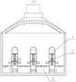
FIG. 1 is a perspective view of an apparatus for drying municipal solid waste according to the present invention;
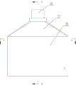
FIG. 2 is a front view of an apparatus for drying municipal solid waste according to the present invention;
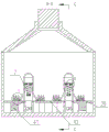
FIG. 3 is a cross-sectional view taken along section line A-A of FIG. 2;
FIG. 4 is a cross-sectional view taken along section line B-B of FIG. 2;
FIG. 5 is a cross-sectional view taken along section line C-C of FIG. 4;
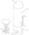
FIG. 6 is a schematic structural diagram of an unpowered thermal expansion type automatic overhead driving device of the municipal solid waste drying device provided by the invention;
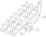
FIG. 7 is a schematic structural diagram of a self-adaptive slow-lifting type upward-lifting layering device of a municipal solid waste drying device according to the present invention;
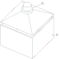
FIG. 8 is a schematic structural view of a one-way flow type semi-sealed box of the municipal solid waste drying device according to the present invention;
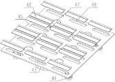
FIG. 9 is a schematic structural view of an automatic sedimentation type unidirectional penetration evaporation prevention rack of the municipal solid waste drying device according to the present invention;
FIG. 10 is an enlarged view of a portion of FIG. 4 at I;
FIG. 11 is an enlarged view of a portion of FIG. 4 at II;
FIG. 12 is an enlarged view of a portion of FIG. 5 at III;
fig. 13 is a partial enlarged view of the portion iv in fig. 3.
Wherein, 1, unpowered heat expansion type automatic overhead driving device, 2, self-adaptive slow lifting type upward-picking layering device, 3, unidirectional flow type semi-sealed box body, 4, automatic sedimentation type unidirectional permeation type evaporation prevention frame, 5, vapor deposition base, 6, dome hollow heat conduction pipe, 7, unpowered heat driving device, 8, base exhaust hole, 9, base clamping table, 10, heat conduction pipe bottom fork, 11, dome, 12, fixed spring base, 13, fixed pre-tightening spring, 14, heat driving piston plate, 15, sealing piston disc, 16, base sector-shaped avoiding groove, 17, base anti-skid sector ring, 18, piston plate bottom boss, 19, piston plate bottom hinge hole, 20, arc self-adaptive upward-picking component, 21, flat plate type upward-picking layering component, 22, lifting type limiting rotating shaft, 23, arc self-adaptive upward-picking rod, 24, translation type limiting rotating shaft, 25. the horizontal movement sliding limiting seat, 26, an upper cantilever laminated plate, 27, a cantilever cylinder, 28, an upper cantilever arc section, 29, an upper cantilever top round hole, 30, an upper cantilever straight section, 31, an upper cantilever bottom boss, 32, an upper cantilever bottom round hole, 33, a limiting seat central sliding groove, 34, a limiting seat waist-shaped sliding hole, 35, a laminated plate strip-shaped groove, 36, a square main box body, 37, a top conical ejector rod, 38, a hot blast device, 39, a box body side air hole, 40, a top cover clamping table, 41, an automatic settling assembly, 42, a one-way permeation assembly, 43, a rigid limiting table, 44, a flexible limiting spring, 45, a lifting permeation plate, 46, a rubber type elastic baffle, 47, a permeation plate, 48 and a permeation plate strip-shaped hole.
The accompanying drawings, which are included to provide a further understanding of the invention and are incorporated in and constitute a part of this specification, illustrate embodiments of the invention and together with the description serve to explain the principles of the invention and not to limit the invention.
Detailed Description
The technical solutions in the embodiments of the present invention will be clearly and completely described below with reference to the drawings in the embodiments of the present invention, and it is obvious that the described embodiments are only a part of the embodiments of the present invention, and not all of the embodiments; all other embodiments, which can be derived by a person skilled in the art from the embodiments given herein without making any creative effort, shall fall within the protection scope of the present invention.
In the description of the present invention, it is to be understood that the terms "upper", "lower", "front", "rear", "left", "right", "top", "bottom", "inner", "outer", and the like, indicate orientations or positional relationships based on the orientations or positional relationships shown in the drawings, and are only for convenience in describing the present invention and simplifying the description, but do not indicate or imply that the device or element referred to must have a particular orientation, be constructed in a particular orientation, and be operated, and thus should not be construed as limiting the present invention.
As shown in figures 1 and 5, the invention provides an urban domestic garbage drying device, which comprises an unpowered thermal expansion type automatic overhead driving device 1, a self-adaptive slow-rising type upward-lifting layered device 2, a one-way flow type semi-sealed box body 3 and an automatic sedimentation type one-way permeation type evaporation prevention frame 4, wherein the unpowered thermal expansion type automatic overhead driving device 1 is arranged in the one-way flow type semi-sealed box body 3 in an array mode, the one-way flow type semi-sealed box body 3 forms a relatively closed space, the unpowered thermal expansion type automatic overhead driving device 1 can take the temperature rising in the box body as a driving force and drive the self-adaptive slow-rising type upward-lifting layered device 2 to move, the self-adaptive slow-rising type upward-lifting layered device 2 is symmetrically arranged on the unpowered thermal expansion type automatic overhead driving device 1, and the self-adaptive slow-rising layered device 2 has two movement steps and can pick up garbage, With the effect of rubbish layering, on the automatic overhead drive arrangement 1 of unpowered heat expansion formula was located in the slip of automatic 4 blocks of settling type one-way permeation evaporation prevention frame, automatic settling type one-way permeation evaporation prevention frame 4 can self-adaptation lift under the effect of gravity to have the effect that prevents the upwards evaporation of moisture.
As shown in fig. 1, 2 and 8, the one-way flow type semi-sealed box 3 includes a square main box 36, a top conical ejector rod 37 and a hot air blower 38, wherein the square main box 36 is provided with a box side air hole 39, the top conical ejector rod 37 is arranged on the square main box 36, the top conical ejector rod 37 is provided with a top cover clamping table 40, the hot air blower 38 is clamped in the top cover clamping table 40, and the hot air blower 38 can blow out hot air from the top.
As shown in fig. 4, 5, 6, 11 and 12, the unpowered thermal expansion type automatic overhead driving device 1 includes a water vapor deposition base 5, a dome hollow heat pipe 6 and a unpowered thermal driving device 7, the water vapor deposition base 5 is arranged at the bottom of a square main box 36 in an array, base exhaust holes 8 are uniformly distributed on the water vapor deposition base 5 in an annular manner, a base clamping table 9 is arranged on the water vapor deposition base 5, the dome hollow heat pipe 6 is clamped on the base clamping table 9, the dome hollow heat pipe 6 is made of metal, the heat conduction pipe has good heat conduction with the surrounding environment, the bottom of the round top hollow heat conduction pipe 6 is symmetrically provided with a heat conduction pipe bottom fork 10, the heat conduction pipe bottom fork 10 can allow water vapor and air to pass through, the round top hollow heat conduction pipe 6 is provided with a heat conduction pipe round top 11, the unpowered heat driving device 7 is clamped in the round top hollow heat conduction pipe 6, and the unpowered heat driving device 7 has a driving function; the unpowered thermal driving device 7 comprises a fixed spring base 12, a fixed pre-tightening spring 13, a thermal driving piston plate 14 and a sealing piston disc 15, wherein the fixed spring base 12 is clamped in a dome hollow heat conduction pipe 6, the fixed spring base 12 is fixedly connected with the dome hollow heat conduction pipe 6, base fan-shaped avoiding grooves 16 are symmetrically arranged on the fixed spring base 12, base anti-skid fan-shaped rings 17 are symmetrically arranged on the fixed spring base 12, the fixed pre-tightening spring 13 is arranged on the fixed spring base 12, the fixed pre-tightening spring 13 can provide pre-tightening force, the thermal driving piston plate 14 is arranged on the fixed pre-tightening spring 13, a piston plate bottom boss 18 is symmetrically arranged at the bottom of the thermal driving piston plate 14, a piston plate bottom hinge hole 19 is arranged on the piston plate bottom boss 18 of the thermal driving piston plate 14, and the sealing piston disc 15 is clamped on the thermal driving piston plate 14, the sealing piston disk 15 is in sliding sealing contact with the inner wall of the domed hollow heat conducting tube 6, and the sealing piston disk 15 acts to seal off air.
As shown in fig. 3, 4, 5, 7 and 10, the adaptive slow-lifting type upward-lifting layering device 2 comprises an arc-shaped adaptive upward-lifting component 20 and a plate-shaped upward-lifting layering component 21, wherein the arc-shaped adaptive upward-lifting component 20 is symmetrically arranged on the heat driving piston plate 14, the arc-shaped adaptive upward-lifting component 20 plays a role in transmission, the plate-shaped upward-lifting layering component 21 is arranged on the arc-shaped adaptive upward-lifting component 20, and the plate-shaped upward-lifting layering component 21 is an executing component; the arc self-adaptive upper cantilever assembly 20 comprises a lifting limiting rotating shaft 22, an arc self-adaptive upper cantilever bar 23, a translational limiting rotating shaft 24 and a translational sliding limiting seat 25, the lifting limiting rotating shaft 22 is rotatably arranged in a piston plate bottom hinge hole 19, an upper cantilever bar arc section 28 is arranged on the arc self-adaptive upper cantilever bar 23, the arc self-adaptive upper cantilever bar 23 is provided with an upper cantilever bar top round hole 29 at the end part of the upper cantilever bar arc section 28, the lifting limiting rotating shaft 22 is clamped in the upper cantilever bar top round hole 29, the arc self-adaptive upper cantilever bar 23 is provided with an upper cantilever bar straight section 30, the arc self-adaptive upper cantilever bar 23 is provided with an upper cantilever bar bottom boss 31 at the joint of the upper cantilever bar arc section 28 and the upper cantilever bar straight section 30, the arc self-adaptive upper cantilever bar 23 is provided with an upper cantilever bar bottom round hole 32 on the upper cantilever bar bottom boss 31, the translational limiting rotating shaft 24 is clamped in the upper cantilever bar bottom round hole 32, the arc-shaped self-adaptive upper ram 23 is in a nearly horizontal state in a no-load low-temperature state, is in a nearly vertical state in a full-load low-temperature state, and is in a nearly horizontal state in a full-load high-temperature state, the arc-shaped self-adaptive upper ram 23 can take partial heat of a drying process as driving force for picking up garbage under the condition that a driving assembly is completely omitted, the translational sliding limiting seat 25 is arranged on the automatic sedimentation type one-way permeation type evaporation prevention frame 4, a limiting seat central sliding chute 33 is arranged on the translational sliding limiting seat 25, the upper ram straight section 30 is clamped and slidably arranged in the limiting seat central sliding chute 33, the translational sliding limiting seat 25 is provided with a limiting seat waist-shaped sliding hole 34 at the limiting seat central sliding chute 33, and the translational limiting rotating shaft 24 is clamped and slidably arranged in the limiting seat waist-shaped sliding hole 34; the flat plate type upward-picking layered assembly 21 comprises an upward-picking layered plate 26 and a picking cylinder 27, the upward-picking layered plate 26 is arranged on an upward-picking rod straight section 30, layered plate strip-shaped grooves 35 are symmetrically formed in the upward-picking layered plate 26, the picking cylinder 27 is arranged on the upward-picking layered plate 26 in an array mode, the upward-picking layered plate 26 can drive the picking cylinder 27 to move when sliding and overturning, the picking cylinder 27 is inserted into household garbage, and the picking cylinder 27 has the function of picking garbage.
As shown in fig. 4, 5 and 9, the automatic sedimentation type unidirectional penetration evaporation-proof rack 4 comprises an automatic sedimentation component 41 and a unidirectional penetration component 42, wherein the automatic sedimentation component 41 is symmetrically arranged at the bottom of the square main box body 36, and the unidirectional penetration component 42 is arranged on the automatic sedimentation component 41; the automatic sedimentation assembly 41 can jack up the unidirectional osmosis assembly 42 in an idle state, the automatic sedimentation assembly 41 comprises a rigid limiting table 43 and a flexible limiting spring 44, the rigid limiting table 43 is symmetrically arranged at the bottom of the square main box body 36, and the flexible limiting spring 44 is arranged at the bottom of the square main box body 36; one-way infiltration subassembly 42 includes over-and-under type infiltration board 45 and rubber formula elastic baffle 46, one-way infiltration subassembly 42 only can allow air and moisture one-way to pass through, can prevent in the evaporation of moisture meeting rubbish of below, over-and-under type infiltration board 45 is located on flexible spacing spring 44, the symmetry is equipped with infiltration board circular port 47 on the over-and-under type infiltration board 45, over-and-under type infiltration board 45 slides through infiltration board circular port 47 block and locates on calotte cavity heat pipe 6, be equipped with infiltration board bar hole 48 on the over-and-under type infiltration board 45, the bottom of over-and-under type infiltration board 45 is located to rubber formula elastic baffle 46 array, rubber formula elastic baffle 46 is located the lower part in infiltration board bar hole 48.
When the garbage can is used specifically, a user firstly needs to pour the water-containing household garbage into the square main box body 36 and lay the garbage on the lifting type penetration plate 45 in a flat manner, the lifting type penetration plate 45 descends under the action of the gravity of the garbage, the flexible limiting spring 44 is compressed in the process until the garbage contacts the rigid limiting table 43, and at the moment, a large amount of water falls below the lifting type penetration plate 45 through the penetrating plate strip-shaped holes 48; then, the hot blast device 38 is started, and the hot blast device 38 blows high-temperature air downwards to dry the wet garbage; blowing high-temperature airflow to the surface layer of the garbage, and drying the garbage on the upper surface layer; as the drying step continues, the temperature in the square main box 36 rises, and thus with the hollow heat pipe 6 in the dome and the air in the heat pipe dome 11 also slowly rise, the square main box 36 keeps its own air pressure equal to the external air pressure through the box side vent 39, and the heat driven piston plate 14 slides by the push of the air in the heat pipe dome 11; in the process, the arc-shaped self-adaptive upper ram 23 gradually slides and rotates, and under the limit of the translational sliding limit seat 25, the garbage is lifted and layered through the flat plate type upper lifting layering component 21, so that high-temperature air can contact the interior of the garbage, and the drying efficiency is increased; finally, air mixed with water vapor in the garbage is exhausted through the air holes 39 in the side face of the box body, the garbage is taken out through a clamping jaw tool after drying is completed, the whole working process is completed, and the step is repeated when the garbage is used next time.
The actual operation process is simple and easy to implement, and only comprises the following steps: pouring the water-containing domestic garbage into the square main box body 36, and flatly spreading the domestic garbage on the lifting type penetration plate 45, wherein the lifting type penetration plate 45 descends under the action of the gravity of the garbage until the domestic garbage contacts the rigid limiting table 43; then, starting the hot blast device 38, and gradually sliding and rotating the arc-shaped self-adaptive upward-picking assembly 20 in the process to pick up and layer the garbage; and finally, taking out the garbage through a clamping jaw tool after drying.
It is noted that, herein, relational terms such as first and second, and the like may be used solely to distinguish one entity or action from another entity or action without necessarily requiring or implying any actual such relationship or order between such entities or actions. Also, the terms "comprises," "comprising," or any other variation thereof, are intended to cover a non-exclusive inclusion, such that a process, method, article, or apparatus that comprises a list of elements does not include only those elements but may include other elements not expressly listed or inherent to such process, method, article, or apparatus.
Although embodiments of the present invention have been shown and described, it will be appreciated by those skilled in the art that changes, modifications, substitutions and alterations can be made in these embodiments without departing from the principles and spirit of the invention, the scope of which is defined in the appended claims and their equivalents.
The present invention and its embodiments have been described above, and the description is not intended to be limiting, and the drawings are only one embodiment of the present invention, and the actual structure is not limited thereto. In summary, those skilled in the art should appreciate that they can readily use the disclosed conception and specific embodiments as a basis for designing or modifying other structures for carrying out the same purposes of the present invention without departing from the spirit and scope of the invention as defined by the appended claims.