CN114016489A - Datum point fixing device for settlement monitoring - Google Patents
Datum point fixing device for settlement monitoring Download PDFInfo
- Publication number
- CN114016489A CN114016489A CN202111406873.9A CN202111406873A CN114016489A CN 114016489 A CN114016489 A CN 114016489A CN 202111406873 A CN202111406873 A CN 202111406873A CN 114016489 A CN114016489 A CN 114016489A
- Authority
- CN
- China
- Prior art keywords
- depth
- drill bit
- settlement
- reference point
- fixing device
- Prior art date
- Legal status (The legal status is an assumption and is not a legal conclusion. Google has not performed a legal analysis and makes no representation as to the accuracy of the status listed.)
- Pending
Links
Images
Classifications
-
- E—FIXED CONSTRUCTIONS
- E02—HYDRAULIC ENGINEERING; FOUNDATIONS; SOIL SHIFTING
- E02D—FOUNDATIONS; EXCAVATIONS; EMBANKMENTS; UNDERGROUND OR UNDERWATER STRUCTURES
- E02D1/00—Investigation of foundation soil in situ
-
- E—FIXED CONSTRUCTIONS
- E02—HYDRAULIC ENGINEERING; FOUNDATIONS; SOIL SHIFTING
- E02D—FOUNDATIONS; EXCAVATIONS; EMBANKMENTS; UNDERGROUND OR UNDERWATER STRUCTURES
- E02D15/00—Handling building or like materials for hydraulic engineering or foundations
- E02D15/02—Handling of bulk concrete specially for foundation or hydraulic engineering purposes
- E02D15/04—Placing concrete in mould-pipes, pile tubes, bore-holes or narrow shafts
-
- E—FIXED CONSTRUCTIONS
- E21—EARTH DRILLING; MINING
- E21B—EARTH DRILLING, e.g. DEEP DRILLING; OBTAINING OIL, GAS, WATER, SOLUBLE OR MELTABLE MATERIALS OR A SLURRY OF MINERALS FROM WELLS
- E21B33/00—Sealing or packing boreholes or wells
- E21B33/10—Sealing or packing boreholes or wells in the borehole
- E21B33/13—Methods or devices for cementing, for plugging holes, crevices, or the like
- E21B33/138—Plastering the borehole wall; Injecting into the formation
-
- E—FIXED CONSTRUCTIONS
- E21—EARTH DRILLING; MINING
- E21B—EARTH DRILLING, e.g. DEEP DRILLING; OBTAINING OIL, GAS, WATER, SOLUBLE OR MELTABLE MATERIALS OR A SLURRY OF MINERALS FROM WELLS
- E21B47/00—Survey of boreholes or wells
-
- E—FIXED CONSTRUCTIONS
- E21—EARTH DRILLING; MINING
- E21B—EARTH DRILLING, e.g. DEEP DRILLING; OBTAINING OIL, GAS, WATER, SOLUBLE OR MELTABLE MATERIALS OR A SLURRY OF MINERALS FROM WELLS
- E21B7/00—Special methods or apparatus for drilling
- E21B7/04—Directional drilling
Abstract
The invention discloses a datum point fixing device for settlement monitoring, wherein a fixing rod comprises a drill bit, a plurality of hollow connecting rods and a grouting guide pipe, the connecting rods are detachably connected end to end, the drill bit is fixedly connected with the bottom end of the connecting rod positioned at the lowest end, the connecting rod positioned at the lowest end is provided with a grouting hole close to the drill bit, the grouting guide pipe sequentially penetrates through the connecting rods and then is communicated with the grouting hole, a settlement plate is placed on the surface of a foundation and can move up and down along the connecting rods, and a displacement sensor can measure the descending depth of the settlement plate and is connected with a collecting device. The method has the advantages of no need of drilling in advance, construction cost saving, convenient field construction and capability of being used for large-area soft foundation treatment settlement automatic monitoring.
Description
Technical Field
The present invention relates to a reference point fixing device for sedimentation monitoring.
Background
In projects of sea reclamation or soft soil areas, foundation treatment is needed to meet the requirements of subsequent engineering construction. The observation of the surface subsidence is one of the monitoring items of the soft foundation treatment engineering, the purpose of the soft foundation treatment is consolidation subsidence, the surface subsidence is the most direct reflection for judging whether the consolidation effect is good or bad, and the surface subsidence is also the basis for controlling the loading rate and calculating the post-construction subsidence and consolidation degree, and the speed of the construction progress and the arrangement of the post-construction are determined.
The traditional manual monitoring method is often adopted for settlement monitoring, but the manual monitoring is time-consuming and labor-consuming, low in efficiency, large and tedious in workload, poor in observation precision and incapable of realizing automatic real-time monitoring.
The automatic monitoring can well solve the problems existing in the manual monitoring, for example, the Chinese patent with the application number of 201910213113.2 and the patent name of an automatic foundation settlement monitoring device based on a laser ranging module, the underground part comprises a steel pipe pile, a laser ranging module and a settlement plate which are driven into and stabilized in a foundation, the overground part comprises a wireless data acquisition module and a data processing terminal, excavation of foundation upper portion around the steel-pipe pile has the equipment fixing groove, and the setting of settlement disk level sets up the bottom at the equipment fixing groove, and laser rangefinder module sets up the top at the settlement disk vertically, and the laser rangefinder module passes through the vertical one side of fixing at the steel-pipe pile of support, and support and laser rangefinder module are installed in the equipment fixing groove, and the laser rangefinder module is equipped with and is located laser range finder, communication module, flash memory card and the group battery of below. The invention can automatically monitor the foundation settlement, does not need manual on-site measurement, can avoid manual measurement errors, has accurate and reliable data and low monitoring cost, and is convenient for specific analysis of the foundation settlement data. However, this automatic monitoring device does not give how to fix the reference motionless point.
For the automatic monitoring of the large-area soft foundation treatment settlement, the success or failure of the automatic settlement monitoring is directly determined by determining the reference motionless point. At present, the reference immobile point is determined by drilling to the position of a bed rock surface and measuring by taking the position of the bed rock surface as a reference point for automatic settlement monitoring, but the drilling cost is higher, and particularly, the construction cost is greatly increased under the condition that the burial depth of the bed rock surface is deeper. And for some weak sites, large-scale drilling machinery cannot enter the site, and the construction difficulty is high.
Disclosure of Invention
The invention provides a datum point fixing device for settlement monitoring, which overcomes the defects in the prior art. The technical scheme adopted by the invention for solving the technical problems is as follows:
the datum point fixing device for settlement monitoring comprises a settlement plate, a fixing rod, a displacement sensor and acquisition equipment, wherein the fixing rod comprises a drill bit, a plurality of hollow connecting rods and a grouting guide pipe, the connecting rods are detachably connected end to end, the drill bit is fixedly connected with the bottom ends of the connecting rods at the lowest end, the connecting rods at the lowest end are provided with grouting holes close to the drill bit, the grouting guide pipe sequentially penetrates through the connecting rods and then is communicated with the grouting holes, the settlement plate is placed on the surface of a foundation and can move up and down along the connecting rods, and the displacement sensor can measure the descending depth of the settlement plate and is connected with the acquisition equipment;
the fixed rod is driven into the soil body until the drill bit moves to a theoretical reference point, and the negative frictional resistance f generated on the connecting rod by the settlement of the soil body above the reference point is comparedsAnd the end resistance f experienced by the drillbBetweenIf f is large or smallb≥fsThe drill bit does not need to be fixed by grouting; if fb≤fsGrouting soil near the drill bit through the grouting guide pipe and the grouting hole to fix the drill bit;
wherein: calculating f using empirical coefficient asI.e. by Wherein pi d is the circumference of the connecting rod, and hi is the thickness of each layer of soil body; according to fb=qπr2Calculating fbWherein q is an empirical end-drag parameter, [ pi ] r2Is the bit plan area.
In a preferred embodiment: calculating the depth of the theoretical reference point:
firstly, a stress ratio method is adopted to calculate the self-weight stress distribution sigma of the soil bodyczAnd additional stress distribution σzTaking σz/σczWhen the soil body at a depth H of 0.2 or less is a highly compressible soil, σ is takenz/σcz0.1 corresponds to a depth H; ② adopting stress area method to calculate depth H, satisfying Δs'iTo calculate the calculated settlement of the ith layer of soil, Δ s ', over the depth range'nTaking the calculated settlement of a soil layer with the thickness of 1m upwards at the calculated depth H; and thirdly, calculating a larger value of the depth by using the two methods, and taking the depth of the surface of the bedrock as the depth of the datum point if the bedrock exists in the depth range.
In a preferred embodiment: the connecting rod top and bottom are equipped with first fixed part and second fixed part respectively, carry out fixed connection through the fixed cooperation of respective first fixed part and second fixed part between two adjacent connecting rods.
In a preferred embodiment: the top of the drill bit is provided with a third fixing part which can be matched with the second fixing part, and the connecting rod is fixedly connected with the drill bit through the fixed matching between the second fixing part and the third fixing part.
In a preferred embodiment: the first fixing part and the third fixing part are both internal threads, and the second fixing part is external threads; or, the first fixing part and the third fixing part are both external threads, and the second fixing part is an internal thread.
In a preferred embodiment: the settlement plate comprises a transverse plate and a vertical sleeve fixedly connected to the center of the transverse plate, the top end of the fixing rod penetrates through the transverse plate and then extends into the vertical sleeve, and the displacement sensor and the acquisition equipment are mounted at the top end of the vertical sleeve.
In a preferred embodiment: the sedimentation plate also comprises reinforcing ribs, wherein the reinforcing ribs are obliquely arranged, one end of each reinforcing rib is fixedly connected with the vertical sleeve, and the other end of each reinforcing rib is fixedly connected with the top surface of the transverse plate.
In a preferred embodiment: the displacement sensor is a stay wire sensor, and the bottom end of a stay wire of the displacement sensor is connected with the top end of the fixed rod.
In a preferred embodiment: the slip casting hole is provided with a plurality of slip casting holes which are arranged at intervals up and down.
In a preferred embodiment: the connecting rod is made of rigid materials.
Compared with the background technology, the technical scheme has the following advantages:
1. the fixing device only needs to drive the drill bit of the fixing rod into the depth of the theoretical reference point and generate negative frictional resistance f to the connecting rod according to the settlement of the soil body above the depth of the reference pointsAnd the end resistance f experienced by the drillbIf f, to perform grouting or non-grouting operationsb≥fsThe drill bit does not need to be fixed by grouting; if fb≤fsAnd grouting soil near the drill bit through the grouting guide pipe and the grouting hole to fix the drill bit. This kind of fixing device can effectively fix the dead lever, can not change the position of dead lever along with the influence that the ground subsides, and the steadiness of dead lever is good. And in addition, the method does not need to drill in advance, saves the construction cost, is convenient for field construction, and can be used for large-area soft foundation treatment settlement automatic monitoring.
2. The calculation of the theoretical datum point depth is that the datum point depth obtained by adopting a stress ratio method and the datum point depth obtained by adopting a stress area method are compared and then are taken out to be larger, so that the calculation of the theoretical datum point depth is more accurate.
Drawings
The invention is further illustrated by the following figures and examples.
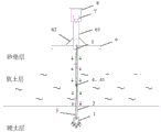
Fig. 1 is a schematic overall view of a reference point fixing device for sedimentation monitoring according to a preferred embodiment.
Detailed Description
In the claims, the specification and the drawings of the present invention, unless otherwise expressly limited, the terms "first", "second" or "third", etc. are used for distinguishing between different items and not for describing a particular sequence.
In the claims, the specification and the drawings of the present invention, unless otherwise expressly limited, all directional or positional relationships indicated by the terms "center," "lateral," "longitudinal," "horizontal," "vertical," "top," "bottom," "inner," "outer," "upper," "lower," "front," "rear," "left," "right," "clockwise," "counterclockwise," and the like are based on the directional or positional relationships indicated in the drawings and are used for convenience in describing the present invention and for simplicity in description, but do not indicate or imply that the device or element so indicated must have a particular orientation or be constructed and operated in a particular orientation, and therefore should not be construed as limiting the scope of the present invention.
In the claims, the description and the drawings of the present application, unless otherwise expressly limited, the terms "fixedly connected" and "fixedly connected" should be interpreted broadly, that is, any connection between the two that is not in a relative rotational or translational relationship, that is, non-detachably fixed, integrally connected, and fixedly connected by other devices or elements.
In the claims, the specification and the drawings of the present invention, the terms "including", "having", and variations thereof, are intended to be inclusive and not limiting.
Referring to fig. 1, a preferred embodiment of the datum point fixing device for settlement monitoring includes a settlement plate, a fixing rod, a displacement sensor 7 and a collecting device 8.
The dead lever includes drill bit 1, the hollow form connecting rod 2 of a plurality of and slip casting pipe 5, and 2 detachably of a plurality of connecting rod carry out end to end, drill bit 1 and the 2 bottom looks rigid couplings of connecting rod that are located the lowest, and the connecting rod 2 that is located the lowest is equipped with the slip casting hole 3 that is close to drill bit 1, slip casting pipe 5 passes behind each connecting rod 2 in proper order and is linked together with slip casting hole 3, the settlement plate is placed on the ground surface and can reciprocate along connecting rod 2, displacement sensor 7 measurable quantity settlement plate's depth of fall is connected with collection equipment 8.
The fixed rod is driven into the soil body until the drill bit 1 moves to a theoretical reference point, and the negative frictional resistance f generated on the connecting rod by the settlement of the soil body above the depth of the reference point is comparedsAnd the end resistance f experienced by the drillbIf f is greater than or equal tob≥fsThe drill bit 1 does not need to be fixed by grouting; if fb≤fsThen, grouting soil near the drill bit 1 through the grouting guide pipe 5 and the grouting hole 3 to fix the drill bit 1;
wherein: calculating f using empirical coefficient asI.e. by Wherein pi d is the 2-week length of the connecting rod, and hi is the thickness of each layer of soil body; according to fb=qπr2Calculating fbWherein q is an empirical end-drag parameter, [ pi ] r2Is the bit plan area.
In this embodiment, the calculation of the depth of the theoretical reference point:
firstly, a stress ratio method is adopted to calculate the self-weight stress distribution sigma of the soil bodyczAnd additional stress distribution σzTaking σz/σczWhen the soil body at a depth H of 0.2 or less is a highly compressible soil, σ is takenz/σcz0.1 corresponds to a depth H; ② adopting stress area method to calculate depth H, satisfying Δs'iTo calculate the calculated settlement of the ith layer of soil, Δ s ', over the depth range'nTaking the calculated settlement of a soil layer with the thickness of 1m upwards at the calculated depth H; and thirdly, calculating a larger value of the depth by using the two methods, and taking the depth of the surface of the bedrock as the depth of the datum point if the bedrock exists in the depth range.
In this embodiment, the top end and the bottom end of each connecting rod 2 are respectively provided with a first fixing portion and a second fixing portion, and two adjacent connecting rods 2 are fixedly connected through the fixing cooperation of the respective first fixing portion and the second fixing portion. And, the top of the drill bit 1 is provided with a third fixing part which can be matched with the second fixing part, and the connecting rod 2 and the drill bit 1 are fixedly connected through the fixed matching between the second fixing part and the third fixing part.
Specifically, the first fixing part and the third fixing part are both internal threads 4, and the second fixing part is an external thread 41; alternatively, the first fixing portion and the third fixing portion may be external threads, and the second fixing portion may be internal threads, as required.
In this embodiment, the three grouting holes 3 are arranged at intervals up and down. And, the said tie rod 2 uses the rigid material.
In this embodiment, the settlement plate includes the horizontal plate 6 and the vertical sleeve 61 of rigid coupling in the horizontal plate 6 center, the dead lever top is passed and is stretched into in the vertical sleeve 61 behind the horizontal plate 6, displacement sensor 7 and collection equipment 8 are all installed in the top department of vertical sleeve 61.
In this embodiment, the settling plate further includes a reinforcing rib 62, and the reinforcing rib 62 is obliquely arranged and has one end fixedly connected to the vertical sleeve 61 and the other end fixedly connected to the top surface of the transverse plate 6.
In this embodiment, the displacement sensor 7 is a pull-wire sensor, and the bottom end of the pull wire is connected to the top end of the fixing rod. The displacement sensor 7 may be other sensors such as a magnetoresistive displacement meter, if necessary, but not limited thereto.
The soft foundation soil body mainly comprises a sand cushion layer, a soft soil layer, a hard soil layer and a foundation layer from top to bottom. The calculated depth of the theoretical datum point is generally located above the basement layer, namely, the fixed rod can be driven into the depth of the theoretical datum point only through a small hammering machine without pre-drilling.
The use method of the datum point fixing device is as follows:
firstly, calculating the depth of a theoretical datum point;
next, it is determined whether a grouting operation is required to fix the drill bit 1. In this example, the value of fb≤fsFor example, grouting soil near the drill bit 1 is needed to fix the drill bit 1;
then, firstly connecting a fixed rod, fixing the drill bit 1 and a connecting rod 2 in a threaded connection mode, driving the fixed rod into the soil body at the surface of the soft foundation treatment site by using a small hammering machine, lengthening the connecting rod 2 when the top end of the connecting rod 2 abuts against the surface of the ground, and continuing to drive the connecting rod downwards until the drill bit 1 is located at the depth of the theoretical reference point;
then, pouring the soil around the drill bit through the grouting guide pipe 5 and the grouting hole 3 to fix the whole fixed rod;
finally, the settlement plate, the displacement sensor 7 and the acquisition equipment 8 are installed, the settlement plate sinks along with the earth surface, the stay wire sensor acquires the settlement amount of the settlement plate and transmits signals to the acquisition equipment 8 when the earth surface sinks, and the acquisition equipment 8 transmits the signals to the server.
The above description is only a preferred embodiment of the present invention, and therefore should not be taken as limiting the scope of the invention, which is defined by the appended claims and their equivalents.
Claims (10)
1. Settlement monitoring is used datum point fixing device which characterized in that: the device comprises a settlement plate, a fixed rod, a displacement sensor and acquisition equipment, wherein the fixed rod comprises a drill bit, a plurality of hollow connecting rods and a grouting guide pipe, the connecting rods are detachably connected end to end, the drill bit is fixedly connected with the bottom end of the connecting rod positioned at the lowest end, the connecting rod positioned at the lowest end is provided with a grouting hole close to the drill bit, the grouting guide pipe sequentially penetrates through the connecting rods and then is communicated with the grouting hole, the settlement plate is placed on the surface of a foundation and can move up and down along the connecting rods, and the displacement sensor can measure the descending depth of the settlement plate and is connected with the acquisition equipment;
the fixed rod is driven into the soil body until the drill bit moves to a theoretical reference point, and the negative frictional resistance f generated on the connecting rod by the settlement of the soil body above the reference point is comparedsAnd the end resistance f experienced by the drillbIf f is greater than or equal tob≥fsThe drill bit does not need to be fixed by grouting; if fb≤fsGrouting soil near the drill bit through the grouting guide pipe and the grouting hole to fix the drill bit;
wherein: calculating f using empirical coefficient asI.e. by Wherein pi d is the circumference of the connecting rod, and hi is the thickness of each layer of soil body; according to fb=qπr2Calculating fbWherein q is an empirical end-drag parameter, [ pi ] r2Is the bit plan area.
2. The reference point fixing device for sedimentation monitoring according to claim 1, wherein: calculating the depth of the theoretical reference point:
firstly, a stress ratio method is adopted to calculate the self-weight stress distribution sigma of the soil bodyczAnd additional stress distribution σzTaking σz/σczWhen the soil body at a depth H of 0.2 or less is a highly compressible soil, σ is takenz/σcz0.1 corresponds to a depth H;
② adopting stress area method to calculate depth H, satisfying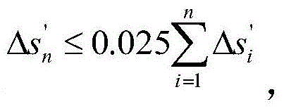 Δs′iTo calculate the calculated settlement of the ith layer of soil, Δ s ', over the depth range'nTaking the calculated settlement of a soil layer with the thickness of 1m upwards at the calculated depth H;
and thirdly, calculating a larger value of the depth by using the two methods, and taking the depth of the surface of the bedrock as the depth of the datum point if the bedrock exists in the depth range.
3. The reference point fixing device for sedimentation monitoring according to claim 2, wherein: the connecting rod top and bottom are equipped with first fixed part and second fixed part respectively, carry out fixed connection through the fixed cooperation of respective first fixed part and second fixed part between two adjacent connecting rods.
4. The reference point fixing device for sedimentation monitoring according to claim 3, wherein: the top of the drill bit is provided with a third fixing part which can be matched with the second fixing part, and the connecting rod is fixedly connected with the drill bit through the fixed matching between the second fixing part and the third fixing part.
5. The reference point fixing device for sedimentation monitoring according to claim 4, wherein: the first fixing part and the third fixing part are both internal threads, and the second fixing part is external threads; or, the first fixing part and the third fixing part are both external threads, and the second fixing part is an internal thread.
6. The reference point fixing device for sedimentation monitoring according to claim 2, wherein: the settlement plate comprises a transverse plate and a vertical sleeve fixedly connected to the center of the transverse plate, the top end of the fixing rod penetrates through the transverse plate and then extends into the vertical sleeve, and the displacement sensor and the acquisition equipment are mounted at the top end of the vertical sleeve.
7. The reference point fixing device for sedimentation monitoring according to claim 6, wherein: the sedimentation plate also comprises reinforcing ribs, wherein the reinforcing ribs are obliquely arranged, one end of each reinforcing rib is fixedly connected with the vertical sleeve, and the other end of each reinforcing rib is fixedly connected with the top surface of the transverse plate.
8. The reference point fixing device for sedimentation monitoring according to claim 1, wherein: the displacement sensor is a stay wire sensor, and the bottom end of a stay wire of the displacement sensor is connected with the top end of the fixed rod.
9. The reference point fixing device for sedimentation monitoring according to claim 1, wherein: the slip casting hole is provided with a plurality of slip casting holes which are arranged at intervals up and down.
10. The reference point fixing device for sedimentation monitoring according to claim 1, wherein: the connecting rod is made of rigid materials.
Priority Applications (1)
| Application Number | Priority Date | Filing Date | Title |
|---|---|---|---|
| CN202111406873.9A CN114016489A (en) | 2021-11-24 | 2021-11-24 | Datum point fixing device for settlement monitoring |
Applications Claiming Priority (1)
| Application Number | Priority Date | Filing Date | Title |
|---|---|---|---|
| CN202111406873.9A CN114016489A (en) | 2021-11-24 | 2021-11-24 | Datum point fixing device for settlement monitoring |
Publications (1)
| Publication Number | Publication Date |
|---|---|
| CN114016489A true CN114016489A (en) | 2022-02-08 |
Family
ID=80066165
Family Applications (1)
| Application Number | Title | Priority Date | Filing Date |
|---|---|---|---|
| CN202111406873.9A Pending CN114016489A (en) | 2021-11-24 | 2021-11-24 | Datum point fixing device for settlement monitoring |
Country Status (1)
| Country | Link |
|---|---|
| CN (1) | CN114016489A (en) |
Cited By (1)
| Publication number | Priority date | Publication date | Assignee | Title |
|---|---|---|---|---|
| CN115095711A (en) * | 2022-06-21 | 2022-09-23 | 广东易力建安工程有限公司 | Construction method of double-anticorrosion plastic-coated composite pipe |
-
2021
- 2021-11-24 CN CN202111406873.9A patent/CN114016489A/en active Pending
Cited By (1)
| Publication number | Priority date | Publication date | Assignee | Title |
|---|---|---|---|---|
| CN115095711A (en) * | 2022-06-21 | 2022-09-23 | 广东易力建安工程有限公司 | Construction method of double-anticorrosion plastic-coated composite pipe |
Similar Documents
| Publication | Publication Date | Title |
|---|---|---|
| CN102162234B (en) | Device and method for monitoring surface displacement of rock-soil body in real time | |
| WO2021017984A1 (en) | Soil pressure and displacement monitoring system and method for miniature steel pipe pile body | |
| CN201109914Y (en) | Apparatus for monitoring sedimentation of soft soil foundation | |
| CN204479060U (en) | A kind of subgrade stability recording geometry | |
| CN103243747B (en) | Deviation rectifying method of prestressed concrete pipe pile foundation | |
| CN101430199A (en) | Method and apparatus for monitoring soft soil base sedimentation | |
| CN1831250A (en) | Construction technology of dry soil taking hole forming method of rotary digging drilling machine | |
| CN204199335U (en) | A kind of pressure release well reducing PHC tube pile construction soil compaction effect | |
| CN105887947A (en) | Deviation rectification method and device for pile foundation inclination | |
| CN102561330A (en) | Integrated construction method for artificial dug pile and steel pipe concrete column | |
| CN207749499U (en) | A kind of dynamic penetrometer | |
| CN104596405B (en) | Rain dirty pipe deforming contact real-time monitoring device and method on ground | |
| CN105332394A (en) | Testing device for researching resistance of uplift piles on abrupt gush damage mechanism of foundation pits | |
| CN208363066U (en) | A kind of soft soil foundation high roadbed Sand roadbed stability monitoring system | |
| CN114016489A (en) | Datum point fixing device for settlement monitoring | |
| CN106643649B (en) | Device and method for measuring deep settlement and pore water pressure of soil body | |
| CN207113887U (en) | Dismountable pit displacement monitoring device | |
| CN207081449U (en) | Device for simultaneously monitoring water content and displacement of slope body | |
| CN102102358B (en) | Method for measuring deep sedimentation deformation of foundation by using wireless conduction water pressure meter | |
| CN105547248A (en) | Quickly-assembled automatic inclinometer casing and monitoring method thereof | |
| CN217298858U (en) | Datum point fixing device for settlement monitoring | |
| CN102183230B (en) | An anchoring device of a datum mark in a boring | |
| CN202073083U (en) | Real-time monitoring device for surface displacement of rock soil body | |
| CN206670618U (en) | A kind of concrete level mark for installing displacement transducer | |
| CN102278975B (en) | Non-contact soft soil large deformation displacement meter |
Legal Events
| Date | Code | Title | Description |
|---|---|---|---|
| PB01 | Publication | ||
| PB01 | Publication | ||
| SE01 | Entry into force of request for substantive examination | ||
| SE01 | Entry into force of request for substantive examination |