CN113975564A - Severe respiratory recovery device - Google Patents
Severe respiratory recovery device Download PDFInfo
- Publication number
- CN113975564A CN113975564A CN202111310885.1A CN202111310885A CN113975564A CN 113975564 A CN113975564 A CN 113975564A CN 202111310885 A CN202111310885 A CN 202111310885A CN 113975564 A CN113975564 A CN 113975564A
- Authority
- CN
- China
- Prior art keywords
- air
- valve
- oxygen
- oxygen cylinder
- pipe
- Prior art date
- Legal status (The legal status is an assumption and is not a legal conclusion. Google has not performed a legal analysis and makes no representation as to the accuracy of the status listed.)
- Granted
Links
- 230000000241 respiratory effect Effects 0.000 title claims abstract description 19
- 238000011084 recovery Methods 0.000 title claims description 15
- 230000007246 mechanism Effects 0.000 claims abstract description 25
- 238000012544 monitoring process Methods 0.000 claims abstract description 23
- QVGXLLKOCUKJST-UHFFFAOYSA-N atomic oxygen Chemical compound [O] QVGXLLKOCUKJST-UHFFFAOYSA-N 0.000 claims description 91
- 229910052760 oxygen Inorganic materials 0.000 claims description 91
- 239000001301 oxygen Substances 0.000 claims description 91
- 239000007789 gas Substances 0.000 claims description 37
- 230000029058 respiratory gaseous exchange Effects 0.000 claims description 14
- 230000005540 biological transmission Effects 0.000 claims description 13
- 230000033001 locomotion Effects 0.000 claims description 12
- 238000000889 atomisation Methods 0.000 claims description 4
- 239000000428 dust Substances 0.000 claims description 4
- 238000004891 communication Methods 0.000 claims description 3
- 230000008878 coupling Effects 0.000 claims description 3
- 238000010168 coupling process Methods 0.000 claims description 3
- 238000005859 coupling reaction Methods 0.000 claims description 3
- 238000000151 deposition Methods 0.000 claims description 3
- 238000010030 laminating Methods 0.000 claims description 3
- 239000007787 solid Substances 0.000 claims description 3
- 238000004659 sterilization and disinfection Methods 0.000 claims description 3
- 230000002146 bilateral effect Effects 0.000 claims description 2
- 210000004072 lung Anatomy 0.000 description 15
- 206010036790 Productive cough Diseases 0.000 description 6
- 208000024794 sputum Diseases 0.000 description 6
- 210000003802 sputum Anatomy 0.000 description 6
- 239000002912 waste gas Substances 0.000 description 6
- 238000007599 discharging Methods 0.000 description 5
- 239000003814 drug Substances 0.000 description 4
- 238000009423 ventilation Methods 0.000 description 4
- 230000006835 compression Effects 0.000 description 3
- 238000007906 compression Methods 0.000 description 3
- 210000003437 trachea Anatomy 0.000 description 3
- CURLTUGMZLYLDI-UHFFFAOYSA-N Carbon dioxide Chemical compound O=C=O CURLTUGMZLYLDI-UHFFFAOYSA-N 0.000 description 2
- 208000004756 Respiratory Insufficiency Diseases 0.000 description 2
- 238000009825 accumulation Methods 0.000 description 2
- 210000000038 chest Anatomy 0.000 description 2
- 238000010586 diagram Methods 0.000 description 2
- 239000007788 liquid Substances 0.000 description 2
- 238000000034 method Methods 0.000 description 2
- 201000004193 respiratory failure Diseases 0.000 description 2
- 206010021143 Hypoxia Diseases 0.000 description 1
- 230000009471 action Effects 0.000 description 1
- 230000002411 adverse Effects 0.000 description 1
- 230000009286 beneficial effect Effects 0.000 description 1
- 210000004204 blood vessel Anatomy 0.000 description 1
- 229910002092 carbon dioxide Inorganic materials 0.000 description 1
- 239000001569 carbon dioxide Substances 0.000 description 1
- 230000002612 cardiopulmonary effect Effects 0.000 description 1
- 238000010790 dilution Methods 0.000 description 1
- 239000012895 dilution Substances 0.000 description 1
- 230000000694 effects Effects 0.000 description 1
- 238000005516 engineering process Methods 0.000 description 1
- 238000010438 heat treatment Methods 0.000 description 1
- 230000007954 hypoxia Effects 0.000 description 1
- 239000012535 impurity Substances 0.000 description 1
- 238000012986 modification Methods 0.000 description 1
- 230000004048 modification Effects 0.000 description 1
- 230000008569 process Effects 0.000 description 1
- 208000023504 respiratory system disease Diseases 0.000 description 1
- 230000002269 spontaneous effect Effects 0.000 description 1
- 208000024891 symptom Diseases 0.000 description 1
- 238000012546 transfer Methods 0.000 description 1
Images


Classifications
-
- A—HUMAN NECESSITIES
- A61—MEDICAL OR VETERINARY SCIENCE; HYGIENE
- A61M—DEVICES FOR INTRODUCING MEDIA INTO, OR ONTO, THE BODY; DEVICES FOR TRANSDUCING BODY MEDIA OR FOR TAKING MEDIA FROM THE BODY; DEVICES FOR PRODUCING OR ENDING SLEEP OR STUPOR
- A61M16/00—Devices for influencing the respiratory system of patients by gas treatment, e.g. mouth-to-mouth respiration; Tracheal tubes
- A61M16/0003—Accessories therefor, e.g. sensors, vibrators, negative pressure
-
- A—HUMAN NECESSITIES
- A61—MEDICAL OR VETERINARY SCIENCE; HYGIENE
- A61M—DEVICES FOR INTRODUCING MEDIA INTO, OR ONTO, THE BODY; DEVICES FOR TRANSDUCING BODY MEDIA OR FOR TAKING MEDIA FROM THE BODY; DEVICES FOR PRODUCING OR ENDING SLEEP OR STUPOR
- A61M11/00—Sprayers or atomisers specially adapted for therapeutic purposes
-
- A—HUMAN NECESSITIES
- A61—MEDICAL OR VETERINARY SCIENCE; HYGIENE
- A61M—DEVICES FOR INTRODUCING MEDIA INTO, OR ONTO, THE BODY; DEVICES FOR TRANSDUCING BODY MEDIA OR FOR TAKING MEDIA FROM THE BODY; DEVICES FOR PRODUCING OR ENDING SLEEP OR STUPOR
- A61M16/00—Devices for influencing the respiratory system of patients by gas treatment, e.g. mouth-to-mouth respiration; Tracheal tubes
- A61M16/0057—Pumps therefor
-
- A—HUMAN NECESSITIES
- A61—MEDICAL OR VETERINARY SCIENCE; HYGIENE
- A61M—DEVICES FOR INTRODUCING MEDIA INTO, OR ONTO, THE BODY; DEVICES FOR TRANSDUCING BODY MEDIA OR FOR TAKING MEDIA FROM THE BODY; DEVICES FOR PRODUCING OR ENDING SLEEP OR STUPOR
- A61M16/00—Devices for influencing the respiratory system of patients by gas treatment, e.g. mouth-to-mouth respiration; Tracheal tubes
- A61M16/06—Respiratory or anaesthetic masks
- A61M16/0683—Holding devices therefor
-
- A—HUMAN NECESSITIES
- A61—MEDICAL OR VETERINARY SCIENCE; HYGIENE
- A61M—DEVICES FOR INTRODUCING MEDIA INTO, OR ONTO, THE BODY; DEVICES FOR TRANSDUCING BODY MEDIA OR FOR TAKING MEDIA FROM THE BODY; DEVICES FOR PRODUCING OR ENDING SLEEP OR STUPOR
- A61M16/00—Devices for influencing the respiratory system of patients by gas treatment, e.g. mouth-to-mouth respiration; Tracheal tubes
- A61M16/10—Preparation of respiratory gases or vapours
- A61M16/105—Filters
- A61M16/106—Filters in a path
- A61M16/107—Filters in a path in the inspiratory path
-
- A—HUMAN NECESSITIES
- A61—MEDICAL OR VETERINARY SCIENCE; HYGIENE
- A61M—DEVICES FOR INTRODUCING MEDIA INTO, OR ONTO, THE BODY; DEVICES FOR TRANSDUCING BODY MEDIA OR FOR TAKING MEDIA FROM THE BODY; DEVICES FOR PRODUCING OR ENDING SLEEP OR STUPOR
- A61M16/00—Devices for influencing the respiratory system of patients by gas treatment, e.g. mouth-to-mouth respiration; Tracheal tubes
- A61M16/10—Preparation of respiratory gases or vapours
- A61M16/12—Preparation of respiratory gases or vapours by mixing different gases
-
- A—HUMAN NECESSITIES
- A61—MEDICAL OR VETERINARY SCIENCE; HYGIENE
- A61M—DEVICES FOR INTRODUCING MEDIA INTO, OR ONTO, THE BODY; DEVICES FOR TRANSDUCING BODY MEDIA OR FOR TAKING MEDIA FROM THE BODY; DEVICES FOR PRODUCING OR ENDING SLEEP OR STUPOR
- A61M16/00—Devices for influencing the respiratory system of patients by gas treatment, e.g. mouth-to-mouth respiration; Tracheal tubes
- A61M16/10—Preparation of respiratory gases or vapours
- A61M16/14—Preparation of respiratory gases or vapours by mixing different fluids, one of them being in a liquid phase
- A61M16/16—Devices to humidify the respiration air
-
- A—HUMAN NECESSITIES
- A61—MEDICAL OR VETERINARY SCIENCE; HYGIENE
- A61M—DEVICES FOR INTRODUCING MEDIA INTO, OR ONTO, THE BODY; DEVICES FOR TRANSDUCING BODY MEDIA OR FOR TAKING MEDIA FROM THE BODY; DEVICES FOR PRODUCING OR ENDING SLEEP OR STUPOR
- A61M31/00—Devices for introducing or retaining media, e.g. remedies, in cavities of the body
-
- A—HUMAN NECESSITIES
- A61—MEDICAL OR VETERINARY SCIENCE; HYGIENE
- A61M—DEVICES FOR INTRODUCING MEDIA INTO, OR ONTO, THE BODY; DEVICES FOR TRANSDUCING BODY MEDIA OR FOR TAKING MEDIA FROM THE BODY; DEVICES FOR PRODUCING OR ENDING SLEEP OR STUPOR
- A61M2202/00—Special media to be introduced, removed or treated
- A61M2202/02—Gases
- A61M2202/0208—Oxygen
Abstract
The invention relates to a severe respiratory restorer, which comprises a base, wherein an air supply mechanism and a mask communicated with the air supply mechanism through an air supply pipe are arranged on the base, rollers are arranged at the lower end of the base, a support column extends upwards on the base, the air supply mechanism is arranged on the support column far away from the base end, the air supply mechanism comprises an air supply part and a monitoring part, a display is arranged on the end surface of the monitoring part, the air supply part is provided with the air supply pipe, and the end of the air supply pipe far away from the air supply part is connected with the mask.
Description
Technical Field
The invention belongs to the technical field of medical equipment, and particularly relates to a severe respiratory recovery device.
Background
The breathing machine is necessary medical equipment for rescuing patients with respiratory failure and treating respiratory system diseases, and can be realized by tracheal cannula type invasive ventilation, the main ventilation modes comprise a volume control ventilation mode and a pressure control ventilation mode, many severe patients can have cardiopulmonary function pause and sometimes even respiratory failure symptoms in the treatment process, however, a plurality of cell tissues of a body can be damaged irreparably due to long-time hypoxia of the body, particularly severe patients, when the respiration is stopped, the most timely and effective method is to forcedly force oxygen into the lung, then the oxygen entering the lung is replaced by carbon dioxide and discharged outwards by utilizing the elastic compression of the lung tissues behind the thorax, and then the patient can gradually recover the spontaneous respiratory capacity by external mechanical chest compression, the existing respiratory restorer mainly adopts a manual compression instrument, oxygen delivery is carried out, and reasonable air inlet and exhalation frequency cannot be controlled; patients with tight occlusions do not have the ability to deliver oxygen, and therefore a need exists for a breathing restorer that can autonomously force oxygen into the lungs.
Disclosure of Invention
The invention aims to solve the problems in the background technology, and provides a severe respiratory recovery device which is simple in structure and convenient to use.
In order to achieve the purpose, the technical scheme adopted by the invention is as follows: the utility model provides a severe breathing restorer, includes the base, is equipped with the face guard that air feed mechanism and air feed mechanism are linked together through the gas-supply pipe on the base, the base lower extreme is equipped with the gyro wheel, and it has the support column to upwards extend on the base, keeps away from the base end on the support column and is equipped with air feed mechanism, and air feed mechanism includes air feed portion and monitoring portion, is equipped with the display on the monitoring portion terminal, is equipped with the gas-supply pipe on the air feed portion, and the gas-supply pipe is kept away from air feed portion end and is connected with the face guard.
Preferably, the support column adopts flexible post, is equipped with the push rod that is convenient for promote the base motion with the support column rigid coupling at the support column rear end face, and the support column side is equipped with at least one oxygen cylinder fixation clamp, is equipped with the containing box that is used for depositing spare part on the support column and the corresponding side of oxygen cylinder fixation clamp.
Preferably, the oxygen cylinder fixing clamp comprises a semicircular annular clamp body, the annular clamp body is connected with the support column in a sliding mode through a connecting plate, a third magic tape rough surface is arranged at one end of the annular clamp body, a third magic tape hook surface matched with the third magic tape rough surface is arranged on the outer side face of the other end of the annular clamp body, and an oxygen cylinder is arranged in the oxygen cylinder fixing clamp body.
Preferably, the oxygen cylinder includes the body with oxygen cylinder fixation clamp matched with, and the body upper end is equipped with the bottleneck, and the bottleneck includes the oxygen cylinder valve, and the oxygen cylinder valve is linked together through the pipeline and the body, and oxygen cylinder valve department is equipped with the manometer of being connected with in the body, is equipped with the adjusting device who is used for adjusting the air current size on the oxygen cylinder valve.
Preferably, be equipped with the buffer tank that is linked together with the oxygen cylinder on the base, the buffer tank lateral surface is equipped with the admission valve that is linked together through gas-supply pipe and oxygen cylinder, admission valve department is equipped with flow sensor, the buffer tank lateral surface still is equipped with the air admission valve, is equipped with the dust cover on the air admission valve, has arranged at least one ultraviolet lamp along medial surface annular in the buffer tank, the buffer tank upper end is equipped with the relief pressure valve that is linked together through gas-supply pipe and air feed mechanism, be equipped with on the base terminal surface and be used for the solid fixed ring fixed with the buffer tank.
Preferably, the air supply mechanism includes air supply portion and monitoring portion, is equipped with control module and communication module in the monitoring portion, and air supply portion lateral surface is equipped with the first oxygen valve that is connected with indoor oxygen, and first oxygen valve is connected with the air transmission pump that is located air supply portion inside through the gas-supply pipe, and air transmission pump one end side is equipped with the gear train, and gear train one end is equipped with the motor.
Preferably, the air delivery pump includes the shell, and one side is equipped with the pivot in the shell, is equipped with the crank in the pivot, connecting rod on the crank, is equipped with the piston on the connecting rod, and the region between piston and the shell constitutes the workspace, and the workspace both sides are equipped with air inlet and gas vent, and the pivot is coaxial with the pinion of gear train, and the pinion bilateral symmetry has arranged the gear wheel, and the gear wheel is equipped with the live-rollers along axis department, is equipped with the cam on the live-rollers, is equipped with the push rod with cam matched with on the shell, and the push rod is kept away from the cam end and is equipped with the valve that closes with air inlet and gas vent matched with.
Preferably, air inlet department is equipped with the three-way valve, and an air inlet of three-way valve is linked together through gas-supply pipe and first oxygen valve or relief pressure valve, and an air inlet of three-way valve is linked together through gas-supply pipe discharge valve, is equipped with the blender in the air feed portion and is linked together through the gas vent of gas-supply pipe with the gas transmission pump, is equipped with ultraviolet disinfection lamp and pressure sensor in the blender, is equipped with the humidifier in the air feed portion and is linked together through gas-supply pipe and blender, is equipped with first relief pressure valve on the blender and is linked together through gas-supply pipe and face guard.
Preferably, the face guard includes the first interface that is linked together with the gas-supply pipe, is equipped with on the face guard and is convenient for carry out the fixed last fixed band and the lower fixed band of fixing with face guard and head, goes up to be equipped with on fixed band and the lower fixed band that the second magic is pasted and first magic is pasted, goes up to be equipped with the screen panel of laminating with the head between fixed band and the lower fixed band.
Preferably, an atomization connecting pipe is arranged at the first connecting port, and a filter is arranged at the outlet of the mixer.
The invention has the beneficial effects that the movement of the breathing restorer is facilitated through the roller wheel, meanwhile, the braking device is arranged at the roller wheel, the breathing restorer is convenient to be fixed in position, the gear set is driven to rotate by adopting the motor, the crank in the air transmission pump is driven to do reciprocating motion, the piston is driven to do reciprocating motion, the large gear of the gear set drives the rotating roller to rotate, the cam on the rotating roller does reciprocating motion to the push rod, and the opening and closing of the air inlet and the air outlet of the air transmission pump are controlled; when the air supply device is used indoors, the air supply device can be connected with an oxygen supply port to supply oxygen into an air supply pump, the air supply pump pressurizes the oxygen entering the air supply pump, the oxygen is pressed into a mixer, the oxygen is diluted and sterilized in the mixer, finally, the air is humidified through a humidifier, the air is pressed into the lung of a patient under the condition that the air supply pump pressurizes, the air is exchanged with blood vessels in the lung, then, the air supply pump contracts, the pressure intensity is reduced, the air in the lung of the patient is pumped out from the lung, and the respiratory circulation of the patient is realized.
Drawings
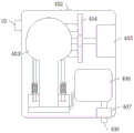
Fig. 1 is a schematic diagram of the critical breathing restorer of the present invention.
Fig. 2 is a schematic view of the mask of the present invention.
Fig. 3 is a schematic view of a surge tank of the present invention.
Fig. 4 is a schematic view of the oxygen cylinder fixing clip of the present invention.
Fig. 5 is a schematic view of an oxygen cylinder of the present invention.
Fig. 6 is a side view of the air supply mechanism of the present invention.
Fig. 7 is a plan view of the gas supply portion of the present invention.
Fig. 8 is a schematic view of the gas transfer pump of the present invention.
Fig. 9 is a schematic view of a humidifier of the present invention.
Fig. 10 is a schematic diagram of a first interface of the present invention.
In the figure: the device comprises a base 1, rollers 2, support columns 3, an air supply mechanism 4, a monitoring part 401, an air supply part 402, an air supply pump 403, a gear set 404, a motor 405, a mixer 406, a humidifier 407, a first pressure reducing valve 408, an air inlet 409, an air outlet 410, an oxygen bottle fixing clamp 5, a ring clamp 501, a third magic tape matt surface 502, a third magic tape hook surface 503, an oxygen bottle 6, an oxygen bottle valve 601, a pressure gauge 602, an adjusting device 603, a display 7, a mask 8, a first connecting port 801, a lower fixing belt 802, a first magic tape 803, an upper fixing belt 804, a mesh enclosure 805, a buffer tank 9, a pressure reducing valve 901, a flow sensor 902, an ultraviolet lamp 903, an air inlet valve 904, a dust hood 905, a first oxygen supply valve 10, an air inlet valve 11, an air pipe 12 and a fixing ring 13.
Detailed Description
For a better understanding of the present invention, reference will now be made to the following examples.
The following further describes embodiments of the present invention with reference to the drawings.
The first embodiment is as follows:
as shown in fig. 1-8, the severe respiratory recovery device comprises a base 1, a face mask 8 which is provided with a gas supply mechanism 4 and communicated with the gas supply mechanism 4 through a gas pipe 12 is arranged on the base 1, rollers 2 are arranged at the lower end of the base 1, a support column 3 is upwards extended on the base 1, the end, far away from the base 1, of the support column 3 is provided with the gas supply mechanism 4, the gas supply mechanism 4 comprises a gas supply part 402 and a monitoring part 401, a display 7 is arranged on the end face of the monitoring part 401, the gas pipe 12 is arranged on the gas supply part 402, and the end, far away from the gas supply part 402, of the gas pipe 12 is connected with the face mask 8.
Oxygen cylinder fixation clamp 5 includes semicircular in shape ring clamp 501, and ring clamp 501 passes through connecting plate and support column 3 sliding connection, and ring clamp 501 one end is equipped with third magic tape matt surface 502, and ring clamp 501 other end lateral surface is equipped with the third magic tape hook face 503 with third magic tape matt surface 502 matched with, is equipped with oxygen cylinder 6 in oxygen cylinder fixation clamp 5.
The oxygen cylinder 6 comprises a cylinder body matched with the oxygen cylinder fixing clamp 5, a bottle mouth is arranged at the upper end of the cylinder body and comprises an oxygen cylinder valve 601, the oxygen cylinder valve 601 is communicated with the cylinder body through a pipeline, a pressure gauge 602 connected with the inside of the cylinder body is arranged at the oxygen cylinder valve 601, and an adjusting device 602 used for adjusting the size of air flow is arranged on the oxygen cylinder valve 601.
Be equipped with the buffer tank 9 that is linked together with oxygen cylinder 6 on base 1, 9 lateral surfaces of buffer tank are equipped with the admission valve 11 that is linked together through gas-supply pipe 12 and oxygen cylinder 6, 11 departments of admission valve are equipped with flow sensor 902, 9 lateral surfaces of buffer tank still are equipped with air admission valve 904, be equipped with dust cover 905 on the air admission valve 904, there is at least one ultraviolet lamp 903 along medial surface annular arrangement in buffer tank 9, 9 upper ends of buffer tank are equipped with the relief pressure valve 901 that is linked together through gas-supply pipe 12 and air feed mechanism 4, be equipped with on the 1 terminal surface of base and be used for the solid fixed ring 13 fixed with buffer tank 9.
The air supply mechanism 4 comprises an air supply part 402 and a monitoring part 401, a control module and a communication module are arranged in the monitoring part 401, a first oxygen supply valve 10 connected with indoor oxygen is arranged on the outer side face of the air supply part 402, the first oxygen supply valve 10 is connected with an air transmission pump 403 positioned in the air supply part 402 through an air transmission pipe 12, a gear set 404 is arranged on the side face of one end of the air transmission pump 403, and an electric motor 405 is arranged at one end of the gear set 404.
The air delivery pump 403 comprises a shell, a rotating shaft is arranged on one side in the shell, a crank is arranged on the rotating shaft, a connecting rod is arranged on the crank, a piston is arranged on the connecting rod, a working area is formed in an area between the piston and the shell, an air inlet 409 and an air outlet 410 are arranged on two sides of the working area, the rotating shaft is coaxial with a pinion of the gear set 404, large gears are symmetrically arranged on two sides of the pinion, a rotating roller is arranged on each large gear along an axis, a cam is arranged on each rotating roller, a push rod matched with the cam is arranged on the shell, and an air closing valve matched with the air inlet 409 and the air outlet 410 is arranged at the end, far away from the cam, of each push rod.
The air inlet 409 is provided with a three-way valve, one air inlet of the three-way valve is communicated with the first oxygen supply valve 10 or the pressure reducing valve 901 through an air conveying pipe 12, one air inlet of the three-way valve is communicated with an exhaust valve of the air conveying pipe 12, a mixer 406 is arranged in the air supply part 402 and is communicated with an exhaust port 410 of the air conveying pump 403 through the air conveying pipe 12, an ultraviolet disinfection lamp and a pressure sensor are arranged in the mixer 406, a humidifier 407 is arranged in the air supply part 402 and is communicated with the mixer 406 through the air conveying pipe 12, and a first pressure reducing valve 408 is arranged on the mixer 406 and is communicated with the mask 8 through the air conveying pipe 12.
The face guard 8 includes the first interface 801 that is linked together with the air-supply pipe 12, is equipped with on the face guard 8 and is convenient for carry out the fixed upper fixing band 804 and the lower fixed band 802 that fix with face guard 8 and head, is equipped with second magic subsides and first magic subsides 803 on upper fixing band 804 and the lower fixed band 802, is equipped with the screen panel 805 with the head laminating between upper fixing band 804 and the lower fixed band 802.
In this embodiment, when the patient is indoors, the oxygen source in the ward is connected to the first oxygen valve 10 through the gas pipe 12, then the respiration monitoring apparatus of the monitoring part 401 is installed on the patient, the respiration state of the patient is monitored in real time, the monitoring data is displayed on the display 7, the monitoring part 401 is provided with a control button, the motor 405 of the gas supply part 401 of the gas transmission pump is started through the control button, the motor 405 drives the pinion in the middle of the gear set 404 to rotate, the pinion drives the gearwheel meshed with the pinion to rotate, the pinion drives the crank to rotate through the rotating shaft, so as to drive the connecting rod and the piston connected with the crank to do reciprocating motion, the two gearwheels drive the rotating roller to rotate, the cam on the rotating roller to do circular motion, thereby realizing the reciprocating motion of the push rod matched with the cam to realize the opening and closing control of the gas inlet 409 and the gas outlet 410 of the gas transmission pump 403, when the air delivery pump 403 inhales air from the outside, a valve communicated with the first oxygen delivery valve 10 in a three-way valve connected with the air inlet 409 is opened, the waste gas valve is closed, a piston moves downwards when inhaling air, the pressure in the air delivery pump 403 is reduced, oxygen enters a working area in the air delivery pump 403 through the air delivery pipe 12, then the piston moves upwards to compress the oxygen inside, at the moment, a push rod at an air outlet 410 moves upwards to open a gas closing valve at the upper end of the push rod, the oxygen enters the mixer 406 through the air outlet 410, the mixer 406 is connected with the air pump through the air delivery pipe 12, a filter layer is arranged at the air inlet of the air pump, the air and the oxygen are mixed in the mixer 406 and humidified through the humidifier 407 after being sterilized, then the oxygen is delivered into the air delivery pipe 12 through a pressure reducing valve 408, the other end of the air delivery pipe 12 is connected with a first connecting port 801 of the mask 8, and the air delivery pipe 12 protrudes out of the inner side of the mask 8, the air pipe 12 of the convex part is inserted into the trachea of a patient, then the face mask 8 is tightly attached to the face of the patient through the upper fixing belt 804, the lower fixing belt 802 and the mesh enclosure 805, oxygen enters the lung through the air pipe 12 to exchange gas, the air pipe 12 between the face mask 8 and the pressure reducing valve 408 is in a Y-shaped structure, the air pipe 12 comprises a passive air suction pipe and a passive exhalation pipe, the passive air suction pipe and the passive exhalation pipe are communicated at the face mask 8, a liquid accumulation bottle is arranged at the joint of the passive exhalation pipe and the air supply part 402, an exhaust three-way valve is arranged at the air outlet 410, the passive exhalation pipe is communicated with the exhaust three-way valve at the air outlet 410, then a piston moves downwards, the valve communicated with the passive exhalation pipe at the air outlet 410 is opened, the valve communicated with the mixer 406 is closed, at the air closing valve at the air outlet 410 is in an open state, the pressure of a working area in the air pump 403 is reduced, the air in the lung of the patient is sucked out, the waste gas in the lung of the patient enters a working area through a passive expiration pipe, then the piston is compressed again, at the moment, the air closing valve at the exhaust port 410 is closed, the air closing valve at the air inlet 409 is opened, the exhaust valve of the three-way valve at the air inlet 409 is opened, the waste gas is discharged through the three-way valve, then the exhaust valve of the three-way valve is closed, and then the piston moves downwards to enter the next cycle, so that the passive breathing cycle is realized when the patient cannot breathe autonomously.
Example two:
as shown in fig. 6, compared with the embodiment 1, the severe respiratory recovery apparatus has an atomizing connection pipe at the first connection port 801, a filter at the outlet of the mixer 406,
in this embodiment, when the patient is outdoors, the oxygen cylinder 6 is fixed on the support column 3 through the oxygen cylinder fixing clamp 5, the support column 3 is a telescopic column, the length of the support column 3 can be adjusted, then the oxygen cylinder valve 601 of the oxygen cylinder 6 is communicated with the air inlet valve 11 of the buffer tank 9 through the air pipe 12, the oxygen enters the buffer tank 9 and then is decompressed and buffered, so as to avoid adverse effects of oxygen pressure fluctuation on the patient, meanwhile, a small amount of air is added into the buffer tank 9 through the air inlet valve for dilution, then the entering air and oxygen are sterilized under the action of the ultraviolet lamp 903 in the buffer tank 9, then the pressure reducing valve 901 of the buffer tank 9 is communicated with the first oxygen supply valve 10 through the air pipe 12, then the respiration monitoring instrument of the monitoring part 401 is installed on the patient, the respiration state of the patient is monitored in real time, and the monitoring data is displayed on the display 7, a control key is arranged on the monitoring part 401, then a motor 405 of the air supply part 401 of the air supply pump is started through the control key, the motor 405 drives a pinion in the middle of a gear set 404 to rotate, the pinion drives a gearwheel meshed with the pinion to rotate, the pinion drives a crank to rotate through a rotating shaft, so that a connecting rod and a piston connected with the crank are driven to reciprocate, two gearwheels drive a rotating roller to rotate, a cam on the rotating roller does circular motion, and therefore a push rod matched with the cam does reciprocating motion to realize the opening and closing control of an air inlet 409 and an air outlet 410 of the air supply pump 403, when the air supply pump 403 sucks air from the buffer tank 9, a valve communicated with a first oxygen supply valve 10 in a three-way valve connected with the air inlet 409 is opened, a waste gas valve is closed, when the piston moves downwards during air suction, the pressure in the air supply pump 403 is reduced, and oxygen enters a working area in the air supply pump 403 through an air supply pipe 12, then the piston moves upwards to compress the oxygen inside, at the moment, the push rod at the exhaust port 410 moves upwards to open the air-closing valve at the upper end of the push rod, the oxygen enters the mixer 406 through the exhaust port 410, the mixer 406 is connected with the air pump through the air pipe 12, the air inlet of the air pump is provided with a filter layer, the air and the oxygen are mixed in the mixer 406 and are disinfected, then a nanometer filter is arranged between the air pipe 12 and the humidifier 407 to further filter impurities in the mixed gas completely, then the mixed gas enters the humidifier 407 to be humidified, the humidifier 407 is provided with a temperature sensor, meanwhile, the humidifier 407 is externally provided with a heating mechanism, then the oxygen is sent into the air pipe 12 through a pressure reducing valve 408, the other end of the air pipe 12 is connected with the first connecting port 801 of the mask 8, the air pipe 12 protrudes out of the mask 8, and the air pipe 12 at the protruding part is inserted into the trachea of a patient, then the face mask 8 is closely attached to the face of the patient through the upper fixing band 804, the lower fixing band 802 and the mesh enclosure 805, oxygen enters the lung through the air pipe 12 to exchange gas, the air pipe 12 between the face mask 8 and the pressure reducing valve 408 is in a Y-shaped structure, the air pipe 12 comprises a passive air suction pipe and a passive exhalation pipe, the passive air suction pipe and the passive exhalation pipe are communicated at the face mask 8, a sputum discharging port is arranged on the outer side face of the first connecting port 801, a sputum discharging buckle communicated with the sputum discharging port is reserved on the air pipe 12, when the patient needs to discharge sputum, sputum in the trachea of the patient is sucked through the sputum discharging port, meanwhile, if the lung of the patient needs to be treated by adding medicine, the medicine can be put into the atomizer, the medicine is communicated with the air pipe 12 through additional atomization, the atomization connecting pipe is communicated with the atomizer, the outlet of the atomizer is communicated with the first connecting port 801, mixing the medicine with the humidified mixed gas, arranging a liquid accumulation bottle at the joint of a passive exhalation pipe and a gas supply part 402, arranging an exhaust three-way valve at an exhaust port 410, communicating the passive exhalation pipe with the exhaust three-way valve at the exhaust port 410, moving a piston downwards, opening a valve communicated with the exhaust three-way valve at the exhaust port 410 and a valve communicated with a mixer 406, closing the valve at the exhaust port 410, reducing the pressure of a working area in a gas transmission pump 403, sucking the gas in the lung of a patient, allowing the waste gas in the lung of the patient to enter the working area through the passive exhalation pipe, compressing the piston again, closing the gas closing valve at the exhaust port 410, opening the gas closing valve at a gas inlet 409, opening an exhaust valve of the three-way valve at the gas inlet 409, discharging the waste gas through the three-way valve, and closing an exhaust valve of the three-way valve, then the piston moves downwards to enter the next cycle, so that the breathing cycle is passively carried out when the patient cannot breathe autonomously.
It should be noted that, for those skilled in the art, many changes and modifications can be made without departing from the spirit and scope of the invention, and the invention is not to be considered limited to the embodiments illustrated in the above description.
Claims (10)
1. The utility model provides a severe breathing restorer, includes base (1), is equipped with air feed mechanism (4) and face guard (8) that are linked together through gas-supply pipe (12) and air feed mechanism (4) on base (1), its characterized in that: base (1) lower extreme is equipped with gyro wheel (2), and it has support column (3) to upwards extend on base (1), keeps away from base (1) end on support column (3) and is equipped with air feed mechanism (4), and air feed mechanism (4) are equipped with display (7) including air feed portion (402) and monitoring portion (401) on monitoring portion (401) terminal surface, are equipped with gas-supply pipe (12) on air feed portion (402), and gas-supply pipe (12) are kept away from air feed portion (402) end and are connected with face guard (8).
2. The severe respiratory recovery apparatus according to claim 1, wherein: support column (3) adopt flexible post, are equipped with the push rod that is convenient for promote base (1) motion with support column (3) rigid coupling at support column (3) rear end face, and support column (3) side is equipped with at least one oxygen cylinder fixation clamp (5), is equipped with the containing box that is used for depositing spare part on support column (3) and the corresponding side of oxygen cylinder fixation clamp (5).
3. The severe respiratory recovery apparatus according to claim 2, wherein: oxygen cylinder fixation clamp (5) are including semicircular in shape ring clamp (501), and ring clamp (501) pass through connecting plate and support column (3) sliding connection, and ring clamp (501) one end is equipped with third magic tape matte surface (502), and ring clamp (501) other end lateral surface is equipped with and pastes hook surface (503) with third magic tape matte surface (502) matched with third magic, is equipped with oxygen cylinder (6) in oxygen cylinder fixation clamp (5).
4. The severe respiratory recovery apparatus according to claim 3, wherein: oxygen cylinder (6) include with oxygen cylinder fixation clamp (5) matched with body, the body upper end is equipped with the bottleneck, the bottleneck includes oxygen cylinder valve (601), oxygen cylinder valve (601) are linked together through pipeline and body, oxygen cylinder valve (601) department is equipped with manometer (602) of being connected with in the body, is equipped with adjusting device (602) that are used for adjusting the air current size on oxygen cylinder valve (601).
5. The severe respiratory recovery apparatus according to claim 4, wherein: be equipped with buffer tank (9) that are linked together with oxygen cylinder (6) on base (1), buffer tank (9) lateral surface is equipped with admission valve (11) that are linked together through gas-supply pipe (12) and oxygen cylinder (6), admission valve (11) department is equipped with flow sensor (902), buffer tank (9) lateral surface still is equipped with air admission valve (904), be equipped with dust cover (905) on air admission valve (904), at least one ultraviolet lamp (903) have been arranged along the medial surface annular in buffer tank (9), buffer tank (9) upper end is equipped with relief pressure valve (901) that are linked together through gas-supply pipe (12) and air feed mechanism (4), be equipped with on base (1) terminal surface and be used for solid fixed ring (13) fixed with buffer tank (9).
6. The severe respiratory recovery apparatus of claim 5, wherein: air feed mechanism (4) are equipped with control module and communication module including air feed portion (402) and monitoring portion (401) in monitoring portion (401), air feed portion (402) lateral surface is equipped with first oxygen valve (10) that are connected with indoor oxygen, first oxygen valve (10) are connected with air transmission pump (403) that are located air feed portion (402) inside through gas-supply pipe (12), air transmission pump (403) one end side is equipped with gear train (404), gear train (404) one end is equipped with motor (405).
7. The severe respiratory recovery apparatus according to claim 6, wherein: air delivery pump (403) includes the shell, one side is equipped with the pivot in the shell, be equipped with the crank in the pivot, connecting rod on the crank, be equipped with the piston on the connecting rod, the region between piston and the shell constitutes the workspace, the workspace both sides are equipped with air inlet (409) and gas vent (410), the pivot is coaxial with the pinion of gear train (404), pinion bilateral symmetry has the gear wheel, the gear wheel is equipped with the live-rollers along axis department, be equipped with the cam on the live-rollers, be equipped with the push rod with cam matched with on the shell, the push rod is kept away from the cam end and is equipped with the valve that closes with air inlet (409) and gas vent (410) matched with.
8. The severe respiratory recovery apparatus according to claim 7, wherein: the mask is characterized in that a three-way valve is arranged at the air inlet (409), one air inlet of the three-way valve is communicated with a first oxygen supply valve (10) or a pressure reducing valve (901) through an air pipe (12), one air inlet of the three-way valve is communicated with an exhaust valve of the air pipe (12), a mixer (406) is arranged in the air supply part (402) and is communicated with an exhaust port (410) of an air supply pump (403) through the air pipe (12), an ultraviolet disinfection lamp and a pressure sensor are arranged in the mixer (406), a humidifier (407) is arranged in the air supply part (402) and is communicated with the mixer (406) through the air pipe (12), and a first pressure reducing valve (408) is arranged on the mixer (406) and is communicated with the mask (8) through the air pipe (12).
9. The severe respiratory recovery apparatus according to claim 8, wherein: the face guard (8) includes first interface (801) that are linked together with gas-supply pipe (12), is equipped with on face guard (8) and is convenient for go on fixed band (804) and fixed band (802) down that fix face guard (8) and head, is equipped with second magic subsides and first magic subsides (803) on fixed band (804) and fixed band (802) down, is equipped with screen panel (805) with the head laminating between fixed band (804) and fixed band (802) down.
10. The severe respiratory recovery apparatus according to claim 9, wherein: an atomization connecting pipe is arranged at the first connecting port (801), and a filter is arranged at the outlet of the mixer (406).
Priority Applications (1)
| Application Number | Priority Date | Filing Date | Title |
|---|---|---|---|
| CN202111310885.1A CN113975564B (en) | 2021-11-08 | 2021-11-08 | Severe respiratory recovery device |
Applications Claiming Priority (1)
| Application Number | Priority Date | Filing Date | Title |
|---|---|---|---|
| CN202111310885.1A CN113975564B (en) | 2021-11-08 | 2021-11-08 | Severe respiratory recovery device |
Publications (2)
| Publication Number | Publication Date |
|---|---|
| CN113975564A true CN113975564A (en) | 2022-01-28 |
| CN113975564B CN113975564B (en) | 2023-11-03 |
Family
ID=79746916
Family Applications (1)
| Application Number | Title | Priority Date | Filing Date |
|---|---|---|---|
| CN202111310885.1A Active CN113975564B (en) | 2021-11-08 | 2021-11-08 | Severe respiratory recovery device |
Country Status (1)
| Country | Link |
|---|---|
| CN (1) | CN113975564B (en) |
Cited By (1)
| Publication number | Priority date | Publication date | Assignee | Title |
|---|---|---|---|---|
| CN114984390A (en) * | 2022-07-22 | 2022-09-02 | 南通大学附属医院 | Wearable inhalation administration equipment for department of respiration |
Citations (9)
| Publication number | Priority date | Publication date | Assignee | Title |
|---|---|---|---|---|
| GB1030404A (en) * | 1962-10-16 | 1966-05-25 | David Ritchie | Improved aid to artificial respiration |
| DE202015106233U1 (en) * | 2015-11-17 | 2016-02-05 | Matthias Godthardt | Device for switching a rebreather from closed to open breathing mode |
| CN108310568A (en) * | 2018-04-20 | 2018-07-24 | 刘琳 | A kind of division of respiratory disease nursing multifunctional breath device |
| CN109692384A (en) * | 2019-01-07 | 2019-04-30 | 李霞 | A kind of Emergence worry oxygen breathing equipment |
| CN111494761A (en) * | 2020-04-21 | 2020-08-07 | 宋方强 | Severe medical science branch of academic or vocational study respiratory recovery ware |
| CN211272950U (en) * | 2019-07-12 | 2020-08-18 | 孙秀红 | Emergency breathing device for internal medicine clinic |
| CN112472939A (en) * | 2020-12-20 | 2021-03-12 | 成都菲斯普科技有限公司 | Medical oxygen supply device for respiratory medicine |
| CN112891693A (en) * | 2021-03-05 | 2021-06-04 | 山西白求恩医院(山西医学科学院) | Anesthesia machine with gaseous automatic humidification function for surgery operation |
| US20210338952A1 (en) * | 2020-05-01 | 2021-11-04 | Groman Inc. | Two pneumatic cylinder medical ventilator, system and method |
-
2021
- 2021-11-08 CN CN202111310885.1A patent/CN113975564B/en active Active
Patent Citations (9)
| Publication number | Priority date | Publication date | Assignee | Title |
|---|---|---|---|---|
| GB1030404A (en) * | 1962-10-16 | 1966-05-25 | David Ritchie | Improved aid to artificial respiration |
| DE202015106233U1 (en) * | 2015-11-17 | 2016-02-05 | Matthias Godthardt | Device for switching a rebreather from closed to open breathing mode |
| CN108310568A (en) * | 2018-04-20 | 2018-07-24 | 刘琳 | A kind of division of respiratory disease nursing multifunctional breath device |
| CN109692384A (en) * | 2019-01-07 | 2019-04-30 | 李霞 | A kind of Emergence worry oxygen breathing equipment |
| CN211272950U (en) * | 2019-07-12 | 2020-08-18 | 孙秀红 | Emergency breathing device for internal medicine clinic |
| CN111494761A (en) * | 2020-04-21 | 2020-08-07 | 宋方强 | Severe medical science branch of academic or vocational study respiratory recovery ware |
| US20210338952A1 (en) * | 2020-05-01 | 2021-11-04 | Groman Inc. | Two pneumatic cylinder medical ventilator, system and method |
| CN112472939A (en) * | 2020-12-20 | 2021-03-12 | 成都菲斯普科技有限公司 | Medical oxygen supply device for respiratory medicine |
| CN112891693A (en) * | 2021-03-05 | 2021-06-04 | 山西白求恩医院(山西医学科学院) | Anesthesia machine with gaseous automatic humidification function for surgery operation |
Cited By (2)
| Publication number | Priority date | Publication date | Assignee | Title |
|---|---|---|---|---|
| CN114984390A (en) * | 2022-07-22 | 2022-09-02 | 南通大学附属医院 | Wearable inhalation administration equipment for department of respiration |
| CN114984390B (en) * | 2022-07-22 | 2023-07-25 | 南通大学附属医院 | Wearable inhalation drug delivery device for respiratory department |
Also Published As
| Publication number | Publication date |
|---|---|
| CN113975564B (en) | 2023-11-03 |
Similar Documents
| Publication | Publication Date | Title |
|---|---|---|
| CN112057715A (en) | Severe medical science branch of academic or vocational study respiratory recovery ware | |
| CN212973802U (en) | Multifunctional respiratory therapy system for hospital and family environment | |
| CN205867254U (en) | Novel anesthesia machine that has disinfection function | |
| CN110559532A (en) | Waste gas treatment device of anesthesia machine | |
| CN110269987B (en) | Artificial respirator with medicine delivery and oxygen delivery functions and use method thereof | |
| CN113975564B (en) | Severe respiratory recovery device | |
| CN108404269B (en) | Breathe internal medicine with breathing therapeutic instrument | |
| CN109939319A (en) | A kind of recyclable anesthetic gases purification device | |
| CN209611914U (en) | Pre hospital care respiratory support systems with oxygen supply, suction sputum and trachea cannula | |
| CN211986581U (en) | A atomizing device for department of respiration nursing | |
| CN210186206U (en) | Recyclable anesthetic gas purification device | |
| CN204637213U (en) | A kind of emergency oxygen apparatus | |
| CN208641462U (en) | A kind of portable respirator | |
| CN109939318A (en) | A kind of Inhalational anesthesia device | |
| CN107929909A (en) | A kind of Emergence clinic breathing equipment and its application method | |
| CN114796757A (en) | Portable emergency respirator for emergency nursing | |
| CN115177836A (en) | Disinfection purifies and nursing device is breathed to humidification integral type | |
| CN2787238Y (en) | Hiccup therapeutic equipment | |
| CN210673973U (en) | Invasive breathing machine for assisting medical operation | |
| CN2319062Y (en) | Circulating helium-oxygen mixing auxiliary breathing appts. | |
| CN207722195U (en) | A kind of severe medicine breathing restorer | |
| CN212369396U (en) | Constant-current type low-ineffective-cavity breathing machine | |
| CN218392039U (en) | Lung function exercise device for respiratory department | |
| CN215653202U (en) | Severe medical science branch of academic or vocational study respiratory recovery ware | |
| CN211068530U (en) | Emergency respirator for internal medicine clinic |
Legal Events
| Date | Code | Title | Description |
|---|---|---|---|
| PB01 | Publication | ||
| PB01 | Publication | ||
| SE01 | Entry into force of request for substantive examination | ||
| SE01 | Entry into force of request for substantive examination | ||
| GR01 | Patent grant | ||
| GR01 | Patent grant |