CN113909363A - Full-automatic feeding and discharging system of numerical control punch - Google Patents
Full-automatic feeding and discharging system of numerical control punch Download PDFInfo
- Publication number
- CN113909363A CN113909363A CN202111293945.3A CN202111293945A CN113909363A CN 113909363 A CN113909363 A CN 113909363A CN 202111293945 A CN202111293945 A CN 202111293945A CN 113909363 A CN113909363 A CN 113909363A
- Authority
- CN
- China
- Prior art keywords
- plate
- punch
- numerical control
- processing
- full
- Prior art date
- Legal status (The legal status is an assumption and is not a legal conclusion. Google has not performed a legal analysis and makes no representation as to the accuracy of the status listed.)
- Pending
Links
- 238000007599 discharging Methods 0.000 title claims abstract description 23
- 238000004080 punching Methods 0.000 claims abstract description 33
- 239000000463 material Substances 0.000 claims abstract description 27
- 230000007246 mechanism Effects 0.000 claims description 19
- 230000000694 effects Effects 0.000 claims description 7
- 238000003754 machining Methods 0.000 claims description 6
- 239000000109 continuous material Substances 0.000 abstract description 2
- 238000011010 flushing procedure Methods 0.000 abstract description 2
- 238000000034 method Methods 0.000 description 8
- 230000008569 process Effects 0.000 description 5
- 238000009434 installation Methods 0.000 description 3
- 238000004519 manufacturing process Methods 0.000 description 2
- FGRBYDKOBBBPOI-UHFFFAOYSA-N 10,10-dioxo-2-[4-(N-phenylanilino)phenyl]thioxanthen-9-one Chemical compound O=C1c2ccccc2S(=O)(=O)c2ccc(cc12)-c1ccc(cc1)N(c1ccccc1)c1ccccc1 FGRBYDKOBBBPOI-UHFFFAOYSA-N 0.000 description 1
- 230000009471 action Effects 0.000 description 1
- 230000009286 beneficial effect Effects 0.000 description 1
- 230000007547 defect Effects 0.000 description 1
- 238000010586 diagram Methods 0.000 description 1
- 230000005484 gravity Effects 0.000 description 1
- 239000002184 metal Substances 0.000 description 1
- 238000012986 modification Methods 0.000 description 1
- 230000004048 modification Effects 0.000 description 1
- 238000003466 welding Methods 0.000 description 1
Images




Classifications
-
- B—PERFORMING OPERATIONS; TRANSPORTING
- B21—MECHANICAL METAL-WORKING WITHOUT ESSENTIALLY REMOVING MATERIAL; PUNCHING METAL
- B21D—WORKING OR PROCESSING OF SHEET METAL OR METAL TUBES, RODS OR PROFILES WITHOUT ESSENTIALLY REMOVING MATERIAL; PUNCHING METAL
- B21D22/00—Shaping without cutting, by stamping, spinning, or deep-drawing
- B21D22/02—Stamping using rigid devices or tools
-
- B—PERFORMING OPERATIONS; TRANSPORTING
- B21—MECHANICAL METAL-WORKING WITHOUT ESSENTIALLY REMOVING MATERIAL; PUNCHING METAL
- B21D—WORKING OR PROCESSING OF SHEET METAL OR METAL TUBES, RODS OR PROFILES WITHOUT ESSENTIALLY REMOVING MATERIAL; PUNCHING METAL
- B21D37/00—Tools as parts of machines covered by this subclass
- B21D37/04—Movable or exchangeable mountings for tools
-
- B—PERFORMING OPERATIONS; TRANSPORTING
- B21—MECHANICAL METAL-WORKING WITHOUT ESSENTIALLY REMOVING MATERIAL; PUNCHING METAL
- B21D—WORKING OR PROCESSING OF SHEET METAL OR METAL TUBES, RODS OR PROFILES WITHOUT ESSENTIALLY REMOVING MATERIAL; PUNCHING METAL
- B21D43/00—Feeding, positioning or storing devices combined with, or arranged in, or specially adapted for use in connection with, apparatus for working or processing sheet metal, metal tubes or metal profiles; Associations therewith of cutting devices
- B21D43/003—Positioning devices
-
- B—PERFORMING OPERATIONS; TRANSPORTING
- B21—MECHANICAL METAL-WORKING WITHOUT ESSENTIALLY REMOVING MATERIAL; PUNCHING METAL
- B21D—WORKING OR PROCESSING OF SHEET METAL OR METAL TUBES, RODS OR PROFILES WITHOUT ESSENTIALLY REMOVING MATERIAL; PUNCHING METAL
- B21D43/00—Feeding, positioning or storing devices combined with, or arranged in, or specially adapted for use in connection with, apparatus for working or processing sheet metal, metal tubes or metal profiles; Associations therewith of cutting devices
- B21D43/02—Advancing work in relation to the stroke of the die or tool
- B21D43/04—Advancing work in relation to the stroke of the die or tool by means in mechanical engagement with the work
Landscapes
- Engineering & Computer Science (AREA)
- Mechanical Engineering (AREA)
- Perforating, Stamping-Out Or Severing By Means Other Than Cutting (AREA)
Abstract
The invention discloses a full-automatic feeding and discharging system of a numerical control punch press, and relates to the field of numerical control punch presses. The device is including processing the punch press, and the internal assembly of processing the punch press has conveyer, and the last fixed surface of processing the punch press installs the support frame, and the lower extreme of support frame is equipped with the punching press head, and the both sides of processing the punch press are equipped with material loading platform and unloading platform respectively. This full-automatic unloading system of going up of numerical control punch press is when using, through placing multiunit panel at the upper surface of material loading platform, along with the increase of panel quantity, multiunit panel pushes down the inside fixing base of material loading platform for the fixing base compresses the inside first spring of material loading platform, and the panel that is located the top all the time with the surface of processing punch press to flushing, and then makes in the course of working, makes things convenient for the continuous material loading of a set of panel, inconvenience when reducing the workman and carrying.
Description
Technical Field
The invention relates to the technical field of numerical control punches, in particular to a full-automatic feeding and discharging system of a numerical control punch.
Background
The numerical control punch is an automatic machine tool equipped with a program control system, can logically process a program specified by a control code or other symbolic instructions and decode the program so as to enable the punch to act and machine parts, can be used for machining various sheet metal parts, and can automatically finish various complex hole patterns and shallow drawing forming machining at one time.
In the production process of numerical control punch press, the material loading unloading operation of panel generally adopts manual operation, at the in-process of carrying out panel material loading, carries through a lot mostly, nevertheless because the punch press has certain height, makes artifical unloading occupy the very big part time of board punching press production for numerical control punch press's high efficiency can not obtain full play, can only carry one at every turn, the condition of repeated operation many times, cause great fatigue for the staff easily.
The size of panel has the difference, and general material loading in-process can't fix a position panel for panel can not place numerical control punch press punching press head place central point accurately and put, and then makes panel shift easily at the material loading in-process, influences the processing of panel, and generally very inconvenient when changing the punching press head, and the welding is inseparable between punching press head and the equipment, makes can not satisfy the different processing demand of panel, to above-mentioned condition, we provide a full-automatic unloading system on numerical control punch press.
Disclosure of Invention
Technical problem to be solved
Aiming at the defects of the prior art, the invention discloses a full-automatic feeding and discharging system of a numerical control punch press, which aims to solve the problems in the prior art.
(II) technical scheme
In order to achieve the purpose, the invention is realized by the following technical scheme: a full-automatic feeding and discharging system of a numerical control punch comprises a feeding device, a discharging device and a discharging device, wherein the feeding device is arranged on the feeding device;
the processing device comprises a processing punch, a conveying belt is assembled inside the processing punch, a bearing plate is assembled on the outer surface of the conveying belt, a support frame is fixedly installed on the upper surface of the processing punch, a punching head is assembled at the lower end of the support frame, and a feeding platform and a discharging platform are respectively assembled on two sides of the processing punch;
the limiting mechanism is installed inside the feeding table and comprises limiting plates, the limiting plates are connected to the upper surface of the feeding table in a sliding mode and are two groups, plates are assembled on the upper surface of the feeding table, and the plates are located between the limiting plates.
Preferably, the feeding table is provided with a moving mechanism, the moving mechanism comprises a placing groove, a first spring and a convex plate, the placing groove is formed in the feeding table, the first spring is movably arranged in the placing groove, and the fixing seat is slidably connected to the inside of the feeding table.
Preferably, one side fixed mounting of fixing base has the flange, the spread groove has been seted up to one side of material loading platform, flange sliding connection is in the inside of spread groove, the last fixed surface of fixing base installs the fixed plate, the last surface mounting of fixed plate has stop gear.
Preferably, stop gear still includes first threaded rod, second threaded rod and screw ring, the inside fixed mounting of fixing base has first threaded rod and second threaded rod, the surface threaded connection of first threaded rod and second threaded rod has the screw ring, the last fixed surface of screw ring installs the limiting plate, the spacing groove has been seted up to the upper surface of fixed plate, the one end of limiting plate is passed through spacing groove sliding connection at the upper surface of fixed plate.
Preferably, the outer surface of the joint of the first threaded rod and the second threaded rod is fixedly sleeved with a first bevel gear, one side of the first bevel gear is meshed with a second bevel gear, a rotating handle is fixedly inserted into the second bevel gear, and one end of the rotating handle is rotatably connected to one side of the fixed seat.
Preferably, the inside of support frame is equipped with the connecting seat, the inside fixed mounting of connecting seat has first gear, the inside threaded connection of first gear has the screw thread piece, the lower fixed surface of screw thread piece installs the punching press head.
Preferably, a strip-shaped groove is formed in one side of the support frame, a pull rod is assembled inside the strip-shaped groove, a fixed block is fixedly installed at one end of the pull rod, an elastic sleeve ring is assembled at one end of the fixed block, and the elastic sleeve ring is movably sleeved on the outer surface of the stamping head and located on the lower surface of the thread block.
Preferably, a clamping plate is fixedly mounted on one side of the fixed block, one end of the clamping plate is movably clamped on the outer surface of the threaded block through a first gear, and a second spring is movably mounted between the pull rod and the fixed block.
Preferably, a blanking table is installed on one side of the processing punch press assembled at the lower end of the support frame, a blanking plate is installed inside the blanking table, and a hydraulic column is fixedly installed on the lower surface of the blanking plate.
Preferably, the PLC controller is installed to S1, one side of support frame, at first through operating the PLC controller, sets for corresponding parameter for the inside conveyer belt of processing punch press drives the loading board and moves together, and at this moment after material loading bench surface mounting' S panel removed to the surface of processing punch press, panel touched the inductor of processing punch press internally mounted.
S2, when the plate touches the sensor arranged inside the processing punch press, the sensor transmits a corresponding signal to the PLC controller, so that the PLC controller drives the punching head for assembling inside the support frame to punch the plate, and drives the connecting seat arranged at one end of the punching head to slide inside the support frame.
S3, after the processing is completed, the PLC is operated, the blanking table is lifted to one side of the processing punch by the PLC, the plate is moved to the upper surface of the blanking table, and then after the plate on the surface of the processing punch is moved out, the sensor transmits information to the PLC, so that the PLC drives the hydraulic column to move up and down, and the plate is conveniently unloaded.
The invention discloses a full-automatic feeding and discharging system of a numerical control punch, which has the following beneficial effects:
1. this full-automatic unloading system of going up of numerical control punch press is when using, through placing multiunit panel at the upper surface of material loading platform, along with the increase of panel quantity, multiunit panel pushes down the inside fixing base of material loading platform, make the fixing base compress the inside first spring of material loading platform, and the panel that is located the top all the time with the surface of processing punch press to flushing, and then make in the course of working, make things convenient for the continuous material loading of a set of panel, it is inconvenient that the manual work only can carry one at every turn to reduce, thereby reduce the influence to machining efficiency.
2. This full-automatic unloading system of going up of numerical control punch press is when using, through the rotation handle that rotates fixing base one side for rotate the handle and drive second bevel gear and rotate, and then make the first bevel gear with second bevel gear engaged with drive two sets of threaded rods and rotate, make two sets of limiting plates of two sets of threaded rod surface threaded connection move to both sides or centre simultaneously, conveniently fix a position the panel of not unidimensional size, and then make panel accurately move numerical control punch press punching press head place central point and put.
3. This full-automatic unloading system of going up of numerical control punch when using, through the pull rod of pull rod support frame internally mounted's connecting seat one side for the pinion rack of pull rod one end shifts out from the gear, and the elastic sleeve ring of pull rod one side installation shifts out from the lower surface of the screw thread piece of punching press head one end installation this moment, then rotates the punching press head, makes the screw thread piece of the one end of punching press head rotate out from the gear, and then conveniently changes the punching press head.
Drawings
FIG. 1 is a schematic diagram of the overall structure of the present invention;
FIG. 2 is a schematic structural view of a loading platform according to the present invention;
FIG. 3 is a schematic view of the internal structure of the loading platform according to the present invention;
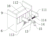
FIG. 4 is a schematic view of a spacing mechanism of the present invention;
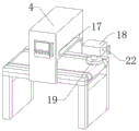
FIG. 5 is a schematic view of a punch head according to the present invention;
FIG. 6 is a schematic view of the internal structure of the punch head according to the present invention;
FIG. 7 is a schematic view of the structure of FIG. 6 at A in accordance with the present invention;
FIG. 8 is a schematic view of the blanking table of the present invention.
In the figure: 1. processing a punch; 2. a conveyor belt; 3. a carrier plate; 4. a support frame; 5. a PLC controller; 6. a feeding table; 7. a plate material; 8. a moving mechanism; 801. a placement groove; 802. a first spring; 803. a convex plate; 9. a fixed seat; 10. a fixing plate; 11. a limiting mechanism; 111. a limiting plate; 112. a first threaded rod; 113. a second threaded rod; 114. a threaded ring; 12. connecting grooves; 13. a first bevel gear; 14. a second bevel gear; 15. rotating the handle; 16. a limiting groove; 17. a strip-shaped groove; 18. a connecting seat; 19. punching a head; 20. a thread block; 21. a first gear; 22. a pull rod; 23. a fixed block; 24. an elastic collar; 25. clamping a plate; 26. a second spring; 27. a blanking table; 28. a hydraulic column.
Detailed Description
The embodiment of the invention discloses a full-automatic feeding and discharging system of a numerical control punch, as shown in figures 1-8, comprising:
referring to fig. 1, processing punch press 1, the internal assembly of processing punch press 1 has conveyer 2, conveyer 2's surface assembly has loading board 3, processing punch press 1's last fixed surface installs support frame 4, one side of support frame 4 is equipped with PLC controller 5, the lower extreme of support frame 4 is equipped with punching press head 19, processing punch press 1's both sides are equipped with material loading platform 6 and unloading platform 27 respectively, through installing material loading platform 6 and unloading platform 27 in processing punch press 1's both sides, and through conveyer 2's effect, conveniently remove panel 7 to punching press head 19's lower extreme through material loading platform 6, then process panel 7.
Referring to fig. 2-3, the feeding table 6 is provided with a moving mechanism 8, the moving mechanism 8 includes a placing groove 801, a first spring 802 and a convex plate 803, the placing groove 801 is formed inside the feeding table 6, the first spring 802 is movably mounted inside the placing groove 801, the fixing base 9 is slidably connected inside the feeding table 6, the convex plate 803 is fixedly mounted on one side of the fixing base 9, the connecting groove 12 is formed on one side of the feeding table 6, the convex plate 803 is slidably connected inside the connecting groove 12, the fixing plate 10 is fixedly mounted on the upper surface of the fixing base 9, the limiting mechanism 11 is mounted on the upper surface of the fixing plate 10, when more plates 7 are placed on the upper surface of the feeding table 6 under the action of the moving mechanism 8, the fixing base 9 inside the feeding table 6 is pressed downward by the groups of plates 7 under the gravity of the groups of plates 7, so that the fixing base 9 compresses the first spring 802 inside the feeding table 6, and the plate 7 positioned at the top is always flush with the surface of the processing punch 1, so that the continuous feeding of a group of plates 7 is facilitated in the processing process.
Referring to fig. 3-4, the device further includes a limiting mechanism 11, the limiting mechanism 11 is installed inside the feeding table 6, the limiting mechanism 11 includes limiting plates 111, two sets of limiting plates 111 are slidably connected to the upper surface of the feeding table 6, plates 7 are installed on the upper surface of the feeding table 6, the plates 7 are located between the limiting plates 111, the limiting mechanism 11 further includes a first threaded rod 112, a second threaded rod 113 and a threaded ring 114, a first threaded rod 112 and a second threaded rod 113 are fixedly installed inside the fixing seat 9, the threaded rings 114 are connected to the outer surfaces of the first threaded rod 112 and the second threaded rod 113 through threads, the limiting plates 111 are fixedly installed on the upper surface of the threaded ring 114, a limiting groove 16 is formed on the upper surface of the fixing plate 10, one end of each limiting plate 111 is slidably connected to the upper surface of the fixing plate 10 through a limiting groove 16, and a plurality of sets of plates 7 are placed between the two sets of limiting plates 111, and through the effect of stop gear 11 for two sets of limiting plate 111 move to both sides simultaneously or middle simultaneously, and then adjust the distance between two sets of limiting plate 111 in order to adapt to the diameter size of panel 7.
Referring to fig. 4, a first bevel gear 13 is fixedly sleeved on the outer surface of the joint of a first threaded rod 112 and a second threaded rod 113, a second bevel gear 14 is engaged with one side of the first bevel gear 13, a rotating handle 15 is fixedly inserted into the second bevel gear 14, one end of the rotating handle 15 is rotatably connected with one side of a fixed seat 9, one end of the feeding table 6 is provided with a groove, so that the rotating handle 15 does not collide with the feeding table 6 in the downward movement process of the fixed seat 9, and the rotating handle 15 is rotated on one side of the fixed seat 9, so that the rotating handle 15 drives the second bevel gear 14 to rotate, and further the first bevel gear 13 engaged with the second bevel gear 14 drives the first threaded rod 112 and the second threaded rod 113 to rotate simultaneously, and the outer surface threads of the first threaded rod 112 and the second threaded rod 113 are opposite, so that two groups of limiting plates 111, which are screwed on the outer surfaces of the first threaded rod 112 and the second threaded rod 113, are simultaneously rotated towards both sides or simultaneously towards both sides The middle of the plate 7 is moved, and then the plate 7 with different lower sizes is limited and positioned.
Referring to fig. 5-6, a connecting seat 18 is assembled inside a supporting frame 4, a first gear 21 is fixedly installed inside the connecting seat 18, a thread block 20 is connected inside the first gear 21 in a threaded manner, a punch 19 is fixedly installed on the lower surface of the thread block 20, a strip-shaped groove 17 is formed in one side of the supporting frame 4, a pull rod 22 is assembled inside the strip-shaped groove 17, a fixing block 23 is fixedly installed at one end of the pull rod 22, an elastic collar 24 is assembled at one end of the fixing block 23, the elastic collar 24 is movably sleeved on the outer surface of the punch 19 and is located on the lower surface of the thread block 20, by screwing one end of the punch 19 inside the first gear 21, and the elastic collar 24 mounted on one end of the pull rod 22 is located at the lower end of the screw block 20 on one end of the punch 19, the screw block 20 is limited so that the screw block 20 does not move out of the inside of the first gear 21.
Referring to fig. 6-7, one side fixed mounting of fixed block 23 has cardboard 25, the one end of cardboard 25 passes through first gear 21 activity joint at the surface of screw block 20, movable mounting has second spring 26 between pull rod 22 and the fixed block 23, the locating hole has been seted up to one side of first gear 21, make one side fixed mounting of fixed block 23 have cardboard 25 can peg graft in the inside of the screw block 20 of punching head 19 one end installation through the locating hole, in order to prevent that punching head 19 from shifting out from the inside of first gear 21, and later stage is through pulling pull rod 22, make cardboard 25 and elastic sleeve ring 24 all separate with screw block 20, and then conveniently shift out punching head 19 from first gear 21, and then reach the purpose of changing punching head 19.
Referring to fig. 8, a blanking table 27 is installed on one side of a processing punch press 1 assembled at the lower end of a support frame 4, a blanking plate is installed inside the blanking table 27, a hydraulic column 28 is fixedly installed on the lower surface of the blanking plate, by operating a PLC controller 5, when a plate 7 leaves from the upper surface of the processing punch press 1, a corresponding signal is transmitted to the PLC controller 5 by an inductor, the PLC controller 5 controls the hydraulic column 28 to lift the blanking table 27 to one side of the processing punch press 1, so that the plate 7 moves to the upper surface of the blanking table 27, the blanking table 27 moves downwards through the hydraulic column 28, and the plate 7 is conveniently unloaded.
In order to make the objects, technical solutions and advantages of the embodiments of the present invention clearer, the technical solutions of the embodiments of the present invention will be clearly and completely described below by way of examples with reference to the accompanying drawings in the present invention.
The working principle is as follows:
when the feeding table 6 is at the initial position, the fixing plate 10 mounted on the upper surface of the fixing seat 9 inside the feeding table 6 is flush with the upper surface of the processing punch 1, and the first spring 802 inside the feeding table 6 is in an extended state.
Further, at first according to the size of the panel 7 that needs to process, adjust the distance between two sets of limiting plate 111 of material loading platform 6 internal assembly, can be earlier through the rotation handle 15 that rotates fixing base 9 one side, make rotation handle 15 drive second bevel gear 14 and rotate, and then make the first bevel gear 13 with second bevel gear 14 meshing drive first threaded rod 112 and second threaded rod 113 and rotate simultaneously, make the screw cup joint to move to both sides or middle simultaneously at two sets of limiting plate 111 of first threaded rod 112 and second threaded rod 113 surface, and then carry out limit positioning to the panel 7 of different lower belt sizes.
Further, then place the upper surface of the fixed plate 10 of the assembly of material loading platform 6 upper surface with multiunit panel 7, when constantly placing panel 7 to the upper surface of fixed plate 10, 7 whole weights of panel constantly increase this moment for multiunit panel 7 constantly produces pressure effect to fixed plate 10 lower surface mounting's fixing base 9, and then makes multiunit panel press down the inside fixing base 9 of material loading platform.
Further, when fixing base 9 moved to the inside standing groove 801 of material loading platform 6, fixing base 9 made the inside first spring 802 of standing groove 801 compressed gradually, and then made the multiunit be located the fixed plate 10 the top board 7 flush with the surface of processing punch press 1 mutually all the time, and then made in the course of working, made things convenient for constantly going on the material loading of a set of board 7.
Before the full-automatic feeding and discharging system of the numerical control punch is used, firstly, according to the processing requirement, one end of the punch 19 is in threaded connection with the inside of the first gear 21, the first gear 21 is fixedly installed in the fixing block 23, then the pull rod 22 is released, the elastic sleeve ring 24 installed at one end of the pull rod 22 is located at the lower end of the thread block 20 at one end of the punch 19, the thread block 20 is limited, and the thread block 20 cannot move out of the inside of the first gear 21.
Meanwhile, one side of the first gear 21 is provided with a positioning hole, so that one side of the fixing block 23 is fixedly provided with a clamping plate 25 which can be inserted into the thread block 20 arranged at one end of the stamping head 19 through the positioning hole, so as to prevent the stamping head 19 from moving out of the first gear 21.
When the full-automatic unloading system of going up of numerical control punch press is using, through operation PLC controller 5 for processing 1 inside conveyer 2 of punch press and driving loading board 3 and moving together, and at this moment after material loading 6 upper surface mounting's panel 7 removed to the surface of processing punch press 1, panel 7 touches the inductor of 1 internally mounted of processing punch press, the corresponding signal of inductor conveying is to PLC controller 5, make PLC controller 5 drive 4 internally mounted's of support frame punching press head 19 carry out the punching press to panel 7.
Finally, when finishing processing to panel 7, panel 7 moves to the upper surface of unloading platform 27 under conveyer 2's effect, when panel 7 that the processing was accomplished leaves from processing punch press 1 upper surface, the corresponding signal of inductor conveying arrives PLC controller 5, get PLC controller 5 control unloading platform 27 inside hydraulic column 28 and promote unloading platform 27 to the one side of processing punch press 1, make panel 7 move to the upper surface of unloading platform 27, rethread control hydraulic column 28 makes unloading platform 27 move down, and then conveniently unload panel 7.
The foregoing shows and describes the general principles and broad features of the present invention and advantages thereof. It will be understood by those skilled in the art that the present invention is not limited to the embodiments described above, which are described in the specification and illustrated only to illustrate the principle of the present invention, but that various changes and modifications may be made therein without departing from the spirit and scope of the present invention, which fall within the scope of the invention as claimed. The scope of the invention is defined by the appended claims and equivalents thereof.
Claims (10)
1. A full-automatic feeding and discharging system of a numerical control punch is characterized by comprising;
the processing punching machine comprises a processing punching machine (1), wherein a conveying belt (2) is assembled inside the processing punching machine (1), a bearing plate (3) is assembled on the outer surface of the conveying belt (2), a supporting frame (4) is fixedly installed on the upper surface of the processing punching machine (1), a PLC (programmable logic controller) (5) is assembled on one side of the supporting frame (4), a punching head (19) is assembled at the lower end of the supporting frame (4), and a feeding platform (6) and a discharging platform (27) are respectively assembled on two sides of the processing punching machine (1);
limiting mechanism (11), limiting mechanism (11) are installed in the inside of material loading platform (6), limiting mechanism (11) are including limiting plate (111), and are two sets of limiting plate (111) sliding connection is at the upper surface of material loading platform (6), the upper surface of material loading platform (6) is equipped with panel (7), panel (7) are located between limiting plate (111).
2. The full-automatic feeding and discharging system of the numerical control punch as claimed in claim 1, wherein: the feeding table is characterized in that a moving mechanism (8) is installed on the feeding table (6), the moving mechanism (8) comprises a placing groove (801), a first spring (802) and a convex plate (803), the placing groove (801) is formed in the feeding table (6), the first spring (802) is movably installed in the placing groove (801), and a fixing seat (9) is connected to the inside of the feeding table (6) in a sliding mode.
3. The full-automatic feeding and discharging system of the numerical control punch as claimed in claim 2, wherein: one side fixed mounting of fixing base (9) has flange (803), spread groove (12) have been seted up to one side of material loading platform (6), flange (803) sliding connection is in the inside of spread groove (12), the last fixed surface of fixing base (9) installs fixed plate (10), the last surface mounting of fixed plate (10) has stop gear (11).
4. The full-automatic feeding and discharging system of the numerical control punch as claimed in claim 3, wherein: stop gear (11) still include first threaded rod (112), second threaded rod (113) and screw ring (114), the inside fixed mounting of fixing base (9) has first threaded rod (112) and second threaded rod (113), the surface threaded connection of first threaded rod (112) and second threaded rod (113) has screw ring (114), the last fixed surface of screw ring (114) installs limiting plate (111), spacing groove (16) have been seted up to the upper surface of fixed plate (10), the upper surface of spacing groove (16) sliding connection at fixed plate (10) is passed through to the one end of limiting plate (111).
5. The full-automatic feeding and discharging system of the numerical control punch as claimed in claim 4, wherein: the outer surface of the joint of the first threaded rod (112) and the second threaded rod (113) is fixedly sleeved with a first bevel gear (13), one side of the first bevel gear (13) is meshed with a second bevel gear (14), the inner part of the second bevel gear (14) is fixedly inserted with a rotating handle (15), and one end of the rotating handle (15) is rotatably connected to one side of the fixed seat (9).
6. The full-automatic feeding and discharging system of the numerical control punch as claimed in claim 1, wherein: the inside of support frame (4) is equipped with connecting seat (18), the inside fixed mounting of connecting seat (18) has first gear (21), the inside threaded connection of first gear (21) has screw block (20), the lower fixed mounting of screw block (20) has punching press head (19).
7. The full-automatic feeding and discharging system of the numerical control punch as claimed in claim 6, wherein: strip-shaped groove (17) have been seted up to one side of support frame (4), the inside in strip-shaped groove (17) is equipped with pull rod (22), the one end fixed mounting of pull rod (22) has fixed block (23), the one end of fixed block (23) is equipped with the elastic sleeve ring (24), the lower surface that just is located screw thread piece (20) at the surface of punching press head (19) is cup jointed in the activity of elastic sleeve ring (24).
8. The full-automatic feeding and discharging system of the numerical control punch as claimed in claim 7, wherein: one side fixed mounting of fixed block (23) has cardboard (25), the one end of cardboard (25) is passed through first gear (21) activity joint in the surface of screw block (20), movable mounting has second spring (26) between pull rod (22) and fixed block (23).
9. The full-automatic feeding and discharging system of the numerical control punch as claimed in claim 8, wherein: the blanking table (27) is installed on one side of the processing punch (1) assembled at the lower end of the support frame (4), a blanking plate is installed inside the blanking table (27), and a hydraulic column (28) is fixedly installed on the lower surface of the blanking plate.
10. The full-automatic feeding and discharging system of the numerical control punch as claimed in any one of claims 1 to 9, wherein:
s1, a PLC controller is installed on one side of the supporting frame, corresponding parameters are set through operating the PLC controller, so that the conveying belt in the machining punch drives the bearing plate to move together, and at the moment, after the plate mounted on the upper surface of the feeding table moves to the surface of the machining punch, the plate touches an inductor mounted in the machining punch.
S2, when the plate touches the sensor arranged inside the processing punch press, the sensor transmits a corresponding signal to the PLC controller, so that the PLC controller drives the punching head for assembling inside the support frame to punch the plate, and drives the connecting seat arranged at one end of the punching head to slide inside the support frame.
S3, after the processing is completed, the PLC is operated, the blanking table is lifted to one side of the processing punch by the PLC, the plate is moved to the upper surface of the blanking table, and then after the plate on the surface of the processing punch is moved out, the sensor transmits information to the PLC, so that the PLC drives the hydraulic column to move up and down, and the plate is conveniently unloaded.
Priority Applications (1)
| Application Number | Priority Date | Filing Date | Title |
|---|---|---|---|
| CN202111293945.3A CN113909363A (en) | 2021-11-03 | 2021-11-03 | Full-automatic feeding and discharging system of numerical control punch |
Applications Claiming Priority (1)
| Application Number | Priority Date | Filing Date | Title |
|---|---|---|---|
| CN202111293945.3A CN113909363A (en) | 2021-11-03 | 2021-11-03 | Full-automatic feeding and discharging system of numerical control punch |
Publications (1)
| Publication Number | Publication Date |
|---|---|
| CN113909363A true CN113909363A (en) | 2022-01-11 |
Family
ID=79244915
Family Applications (1)
| Application Number | Title | Priority Date | Filing Date |
|---|---|---|---|
| CN202111293945.3A Pending CN113909363A (en) | 2021-11-03 | 2021-11-03 | Full-automatic feeding and discharging system of numerical control punch |
Country Status (1)
| Country | Link |
|---|---|
| CN (1) | CN113909363A (en) |
Cited By (1)
| Publication number | Priority date | Publication date | Assignee | Title |
|---|---|---|---|---|
| CN115007933A (en) * | 2022-07-12 | 2022-09-06 | 苏州达观克电子科技有限公司 | Board cutting machine capable of automatically feeding |
Citations (7)
| Publication number | Priority date | Publication date | Assignee | Title |
|---|---|---|---|---|
| JPH0639458A (en) * | 1991-05-17 | 1994-02-15 | Amada Co Ltd | Punch press machine |
| CN209006562U (en) * | 2018-10-26 | 2019-06-21 | 嘉兴亿宸龙箱包有限公司 | A kind of press machine |
| CN211135111U (en) * | 2019-12-15 | 2020-07-31 | 青岛崎美塑料制品有限公司 | Punch press device with go up unloading function |
| CN211304522U (en) * | 2019-12-03 | 2020-08-21 | 南京瀚孚机械有限公司 | EI piece tempering is with loading tray's feed arrangement |
| CN211758056U (en) * | 2020-03-19 | 2020-10-27 | 任圆圆 | Mechanical die mounting seat convenient for replacing die head |
| CN112676440A (en) * | 2020-12-09 | 2021-04-20 | 廖日豪 | Many specifications aluminum alloy stamping device |
| CN216606820U (en) * | 2021-11-03 | 2022-05-27 | 惠州市华兴誉实业有限公司 | Full-automatic feeding and discharging system of numerical control punch |
-
2021
- 2021-11-03 CN CN202111293945.3A patent/CN113909363A/en active Pending
Patent Citations (7)
| Publication number | Priority date | Publication date | Assignee | Title |
|---|---|---|---|---|
| JPH0639458A (en) * | 1991-05-17 | 1994-02-15 | Amada Co Ltd | Punch press machine |
| CN209006562U (en) * | 2018-10-26 | 2019-06-21 | 嘉兴亿宸龙箱包有限公司 | A kind of press machine |
| CN211304522U (en) * | 2019-12-03 | 2020-08-21 | 南京瀚孚机械有限公司 | EI piece tempering is with loading tray's feed arrangement |
| CN211135111U (en) * | 2019-12-15 | 2020-07-31 | 青岛崎美塑料制品有限公司 | Punch press device with go up unloading function |
| CN211758056U (en) * | 2020-03-19 | 2020-10-27 | 任圆圆 | Mechanical die mounting seat convenient for replacing die head |
| CN112676440A (en) * | 2020-12-09 | 2021-04-20 | 廖日豪 | Many specifications aluminum alloy stamping device |
| CN216606820U (en) * | 2021-11-03 | 2022-05-27 | 惠州市华兴誉实业有限公司 | Full-automatic feeding and discharging system of numerical control punch |
Cited By (1)
| Publication number | Priority date | Publication date | Assignee | Title |
|---|---|---|---|---|
| CN115007933A (en) * | 2022-07-12 | 2022-09-06 | 苏州达观克电子科技有限公司 | Board cutting machine capable of automatically feeding |
Similar Documents
| Publication | Publication Date | Title |
|---|---|---|
| CN103394606B (en) | Full-automatic feeding device of punching machine | |
| CN110883510B (en) | Sleeve work piece upset pressure equipment mechanism | |
| CN110814191B (en) | Full-automatic pipe expanding machine and pipe expanding method | |
| CN101020248A (en) | Automatic feeder of machine tool | |
| CN102228925B (en) | Numerical control metal spinning machine and software operating method thereof | |
| CN108637776B (en) | Rotary feeding and discharging machine | |
| CN108296577B (en) | PMC car silk machine material loading manipulator | |
| CN202701893U (en) | Bin adjustable tray of automatic grabbing production line | |
| CN216606820U (en) | Full-automatic feeding and discharging system of numerical control punch | |
| CN210060337U (en) | Automatic clamp spring press-fitting equipment | |
| CN113909363A (en) | Full-automatic feeding and discharging system of numerical control punch | |
| CN109079047B (en) | Automatic feeding and discharging equipment of stamping robot | |
| CN111185791A (en) | Feeding and discharging mechanism and machine tool | |
| CN209614869U (en) | A kind of part end face Multi-station synchronous processing tool | |
| CN203751620U (en) | Automatic burnishing machine | |
| CN116673423A (en) | Bearing frame forging equipment | |
| CN116619015A (en) | Pipe joint assembling equipment | |
| CN211165434U (en) | Press machine | |
| CN202037223U (en) | Numerical control metal spinning machine | |
| CN108942365B (en) | Automatic feeding and discharging device of motor end cover porous drilling machine equipment | |
| CN220862739U (en) | Numerical control lathe with automatic feeding and discharging functions | |
| CN208600606U (en) | Flange location locking mechanism | |
| CN207807122U (en) | A kind of building-block machine multistation processing structure | |
| CN111807055A (en) | Double-station feeder | |
| CN206343955U (en) | A kind of automatic numerical control lathe automatic loading/unloading feed bin and automatic clamping robotic device |
Legal Events
| Date | Code | Title | Description |
|---|---|---|---|
| PB01 | Publication | ||
| PB01 | Publication | ||
| SE01 | Entry into force of request for substantive examination | ||
| SE01 | Entry into force of request for substantive examination |