CN113826594B - Tea garden pest control is with catching device of killing based on insect phototaxis is traped escape prevention - Google Patents
Tea garden pest control is with catching device of killing based on insect phototaxis is traped escape prevention Download PDFInfo
- Publication number
- CN113826594B CN113826594B CN202111107493.5A CN202111107493A CN113826594B CN 113826594 B CN113826594 B CN 113826594B CN 202111107493 A CN202111107493 A CN 202111107493A CN 113826594 B CN113826594 B CN 113826594B
- Authority
- CN
- China
- Prior art keywords
- pipe
- pest
- shell
- tea garden
- trapping
- Prior art date
- Legal status (The legal status is an assumption and is not a legal conclusion. Google has not performed a legal analysis and makes no representation as to the accuracy of the status listed.)
- Active
Links
Images


Classifications
-
- A—HUMAN NECESSITIES
- A01—AGRICULTURE; FORESTRY; ANIMAL HUSBANDRY; HUNTING; TRAPPING; FISHING
- A01M—CATCHING, TRAPPING OR SCARING OF ANIMALS; APPARATUS FOR THE DESTRUCTION OF NOXIOUS ANIMALS OR NOXIOUS PLANTS
- A01M1/00—Stationary means for catching or killing insects
- A01M1/08—Attracting and catching insects by using combined illumination or colours and suction effects
-
- A—HUMAN NECESSITIES
- A01—AGRICULTURE; FORESTRY; ANIMAL HUSBANDRY; HUNTING; TRAPPING; FISHING
- A01M—CATCHING, TRAPPING OR SCARING OF ANIMALS; APPARATUS FOR THE DESTRUCTION OF NOXIOUS ANIMALS OR NOXIOUS PLANTS
- A01M1/00—Stationary means for catching or killing insects
- A01M1/22—Killing insects by electric means
- A01M1/223—Killing insects by electric means by using electrocution
-
- Y—GENERAL TAGGING OF NEW TECHNOLOGICAL DEVELOPMENTS; GENERAL TAGGING OF CROSS-SECTIONAL TECHNOLOGIES SPANNING OVER SEVERAL SECTIONS OF THE IPC; TECHNICAL SUBJECTS COVERED BY FORMER USPC CROSS-REFERENCE ART COLLECTIONS [XRACs] AND DIGESTS
- Y02—TECHNOLOGIES OR APPLICATIONS FOR MITIGATION OR ADAPTATION AGAINST CLIMATE CHANGE
- Y02A—TECHNOLOGIES FOR ADAPTATION TO CLIMATE CHANGE
- Y02A50/00—TECHNOLOGIES FOR ADAPTATION TO CLIMATE CHANGE in human health protection, e.g. against extreme weather
- Y02A50/30—Against vector-borne diseases, e.g. mosquito-borne, fly-borne, tick-borne or waterborne diseases whose impact is exacerbated by climate change
Abstract
The invention discloses a tea garden pest control trapping and killing device based on pest phototaxis for trapping and preventing escape, which comprises a shell, a top cover, a pest inlet, barbs, an electric network and a trap lamp, wherein the top cover is fixedly installed at the upper end of the shell, a funnel-shaped pest inlet convenient for pests to enter is formed in the side of the shell, the barbs are fixedly arranged in the pest inlet, the electric network for electrically killing the entering pests is installed in the shell, and the trap lamp for emitting a trapping light source is arranged on the inner side of the electric network; further comprising: the cleaning brush is arranged in the shell, and a blocking screen plate is arranged below the inner part of the shell; the moving block is sleeved at the upper end of the flow guide pipe; the upper end of the water suction pipe is connected with the auxiliary cavity. This tea garden sick worm prevention and cure based on insect phototaxis is traped anti-escape is with catching and killing device can reduce the possibility that the pest appears escaping, can play good cooling effect to luring the fluorescent tube simultaneously, improves follow-up electric wire netting and kills the effect to the pest.
Description
Technical Field
The invention relates to the technical field of tea garden pest control, in particular to a catching and killing device for tea garden pest control, which is used for catching and preventing escape based on phototaxis of pests.
Background
Tea garden is the region that is used for planting tealeaves, when planting tealeaves in the tea garden, can unavoidably have corresponding pest in the tea garden, kills through spraying chemical agent in order to prevent and treat the pest mostly in the past, but chemical agent influences the quality of tealeaves after spraying easily, consequently kills the pest to the mode that solves this type of problem and all can trap usually.
However, the prior trapping and killing device has the following problems:
the pest trapping device for tea garden pest control comprises a top seat and a base, wherein a transparent outer cover pipe, a power grid cover pipe, a transparent inner cover pipe and an inducing lamp tube are sequentially fixed on the lower side of the top seat;
(1) in the process of catching pests, the pests enter the device through the through hole, and the pests are killed by using an internal power grid, wherein the through hole is not provided with a corresponding escape-proof structure, the pests are easy to escape after entering the device, meanwhile, some pest power grids only have a corona effect, and the pests can still move or even escape from the inside of the through hole after being recovered for a period of time;
(2) the trapping device is internally provided with the corresponding trapping lamp tube to trap pests by utilizing phototaxis of the pests, but the trapping lamp tube is easy to have high temperature after being used for a long time, so the service life of the trapping lamp tube is easy to reduce for a long time;
(3) inside electric wire netting structure is after long-time use, adheres to a large amount of pests easily on the electric wire netting, and these pests influence the holistic electrically conductive effect of electric wire netting easily after adhering to on the electric wire netting to lead to can not electrocute it the very first time after the pest touches.
Therefore, we have proposed a catching and killing device for preventing and controlling diseases and insects in a tea garden based on phototaxis trapping and escape of pests so as to solve the problems set forth above.
Disclosure of Invention
The invention aims to provide a phototaxis trapping and anti-escape catching and killing device for controlling diseases and insects in a tea garden, which is used for solving the problems that the pests are easy to escape in the catching and killing process of the existing catching and killing device in the market, the high temperature of an inducing lamp tube is easy to occur after long-time use, and the subsequent killing effect on the pests is easy to influence after a large amount of pests are attached to a power grid.
In order to achieve the purpose, the invention provides the following technical scheme: a tea garden pest control based on insect phototaxis is trapped and is prevented escape with catching and killing device, includes casing, top cap, insect inlet, barb, electric wire netting and moth-killing lamp, the upper end fixed mounting of casing has the top cap, and the avris of casing is provided with the infundibulate insect inlet that is convenient for the pest to get into, and the inside fixed barb that is provided with of insect inlet, the inside of casing is installed and is gone into the electric wire netting that the pest electricity killed, and the inboard of electric wire netting is provided with the moth-killing lamp that sends and trap the light source;
further comprising:
the cleaning brush is arranged in the shell, the barrier screen plate is arranged below the interior of the shell, the middle of the lower end of the shell is provided with a servo motor for providing power, and the output end of the servo motor is connected with a flow guide pipe;
the moving block is sleeved at the upper end of the flow guide pipe, the moving block and the inner end of the piston block are connected with each other through a transmission rod, and the piston block is arranged in the auxiliary cavity;
one end of the linking pipe is communicated with the auxiliary cavity, the other end of the linking pipe is arranged on the side of the central pipe, and the lower end of the central pipe and the upper end of the flow guide pipe are connected with each other through a bearing;
the upper end of the water suction pipe is connected with the auxiliary cavity, the other end of the water suction pipe is arranged in the water tank, and the water suction pipe and the connecting pipe are both provided with one-way valves;
the negative pressure fan is fixedly arranged on the flow guide pipe, the negative pressure fan is arranged inside the sleeve, and a branch pipeline is arranged on the side of the sleeve;
and the contact block is arranged on the outer side of the flow guide pipe and is connected with the trap lamp through the heat conduction column.
Preferably, the height of the cleaning brush is equal to the height of the power grid, the cleaning brush is attached to the power grid, and the power grid is fixedly connected with the flow guide pipe.
Through adopting above-mentioned technical scheme, thereby utilize the setting of cleaning brush to clean the pest corpse that adheres to on the electric wire netting surface, guarantee the cleanliness factor of electric wire netting, avoid the pest corpse to influence the electrically conductive effect of electric wire netting.
Preferably, the upper end of the guide pipe is provided with reciprocating threads, the guide pipe is in threaded connection with the moving block, and the guide pipe and the center pipe are both provided with hollow structures.
By adopting the technical scheme, the rotation of the flow guide pipe can utilize the reciprocating threads at the upper end of the flow guide pipe to enable the moving block to move up and down in a reciprocating mode.
Preferably, the moving block and the piston block are movably connected with the end part of the transmission rod, and a sliding connection structure is formed between the piston block and the auxiliary cavity.
By adopting the technical scheme, the piston block can reciprocate leftwards and rightwards in the auxiliary cavity under the action of the movably connected transmission rod by utilizing the vertical reciprocating movement of the movable block.
Preferably, the interior of the sleeve is a hollow structure, and the sleeve and the guide pipe are connected with each other through a bearing.
Through adopting above-mentioned technical scheme, the honeycomb duct can avoid driving the sleeve pipe through the bearing and carry out synchronous revolution at rotatory in-process.
Preferably, the lateral sides of the sleeves are uniformly distributed with branch pipes, the outer ends of the branch pipes are arranged to be open, and the branch pipes are communicated with the sleeves.
Through adopting above-mentioned technical scheme, can introduce its outside air to the inside of sheathed tube through the lateral conduit after the inside negative pressure that produces of sleeve pipe.
Preferably, the branched pipelines correspond to the insect inlets on the side edge of the shell one by one, and the outer end openings of the branched pipelines and the insect inlets are positioned on the same horizontal straight line.
By adopting the technical scheme, the branch pipeline can attract pests entering from the pest inlet after generating negative pressure, and the probability of escaping of the pests is reduced.
Preferably, the contact blocks are uniformly distributed in the sleeve, and the uniformly distributed contact blocks are connected with the trap lamp through the heat conduction columns.
Through adopting above-mentioned technical scheme, the heat that its produced of moth-killing lamp after long-time work can be to the conduction of heat conduction post to the contact block on.
Preferably, be provided with the recess that coincide each other with honeycomb duct side arch on the conflict piece, and the outer wall of conflict piece and honeycomb duct is laminated each other.
Through adopting above-mentioned technical scheme, thereby the protruding area of contact between the touch piece that can improve that sets up on the honeycomb duct utilizes the water source that flows in the honeycomb duct to reduce the absorptive temperature of touch piece.
Compared with the prior art, the invention has the beneficial effects that: the catching and killing device for preventing and controlling the diseases and the pests in the tea garden based on pest phototaxis trapping and escape can reduce the possibility of the pests escaping, simultaneously play a good cooling role on the trapping lamp tube and improve the killing effect of a subsequent power grid on the pests;
1. the device is provided with a branch pipeline, the possibility of the escape of pests can be reduced through the pest inlet of the funnel-shaped structure and the barbs arranged in the funnel-shaped structure, and meanwhile, when the negative pressure fan rotates, external air can be introduced into the sleeve through the branch pipeline, so that the opening of the branch pipeline generates negative pressure, and at the moment, the negative pressure fan can attract the pests entering from the pest inlet, so that the possibility of the escape of the pests is further reduced;
2. the water source can be sprayed out through the guide pipe and the water spraying pipe arranged on the guide pipe, pests staying on the inclined plane of the bottom of the shell after corona can be washed onto the separation screen plate by utilizing the sprayed water source, the used water source enters the water tank to be recycled, pest wings after corona can be wetted by the sprayed water source, the flying difficulty of the pests is increased, and meanwhile, the pests staying on the inclined plane can be washed onto the separation screen plate collectively, so that the subsequent centralized treatment of the pests is facilitated;
3. be provided with to the touch multitouch, the moth-killing lamp can be conducted to the touch multitouch on by the heat conduction post through its temperature that produces after long-time use, thereby can carry out the heat transfer to the touch multitouch through the water source of carrying in the honeycomb duct this moment, thereby reduce the absorptive temperature of touch multitouch, simultaneously after negative pressure fan introduces the inside back of sheathed tube with external cold air through the lateral conduit, thereby can carry out further cooling to the touch multitouch through the air of introducing, avoid the moth-killing lamp to be in high temperature state for a long time after long-term work, improve the life of its moth-killing lamp.
Drawings
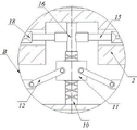
FIG. 1 is a schematic sectional front view of the present invention;
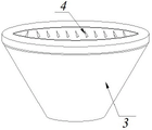
FIG. 2 is a schematic view of the three-dimensional structure of the insect inlet and the barbs of the present invention;
FIG. 3 is an enlarged view of the structure at A in FIG. 1 according to the present invention;
FIG. 4 is an enlarged view of the structure at B in FIG. 1 according to the present invention;
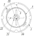
FIG. 5 is a schematic top-down view of the power grid and cleaning brush of the present invention;
FIG. 6 is a perspective view of the cannula and branch conduit of the present invention;
FIG. 7 is a schematic cross-sectional view of a flow guide tube and a collision block according to the present invention;
fig. 8 is a schematic perspective view of a collision block according to the present invention.
In the figure: 1. a housing; 2. a top cover; 3. an insect inlet; 4. a barb; 5. a power grid; 6. a trap lamp; 7. a cleaning brush; 8. blocking the screen plate; 9. a servo motor; 10. a flow guide pipe; 11. a moving block; 12. a transmission rod; 13. a piston block; 14. an auxiliary cavity; 15. connecting the pipe; 16. a central tube; 17. a suction pipe; 18. a one-way valve; 19. a water tank; 20. a negative pressure fan; 21. a sleeve; 22. a branch pipe; 23. a contact block; 24. a heat-conducting column.
Detailed Description
The technical solutions in the embodiments of the present invention will be clearly and completely described below with reference to the drawings in the embodiments of the present invention, and it is obvious that the described embodiments are only a part of the embodiments of the present invention, and not all of the embodiments. All other embodiments, which can be obtained by a person skilled in the art without making any creative effort based on the embodiments in the present invention, belong to the protection scope of the present invention.
Referring to fig. 1-8, the present invention provides a technical solution: a tea garden pest control based on pest phototaxis is trapped and is prevented escaping with catching and killing device, including body 1, top cap 2, enter the insect mouth 3, barb 4, electric wire netting 5 and moth-killing lamp 6, the upper end of the body 1 is fixedly equipped with the top cap 2, and the avris of the body 1 has funnel-shaped that facilitates the pest to enter into and enter the insect mouth 3, and enter the inside of the insect mouth 3 and fixedly equipped with the barb 4, the inside of the body 1 is fitted with and entered the electric wire netting 5 that the pest electricity kills, and the inboard of the electric wire netting 5 has sending and traps the moth-killing lamp 6 of the light source;
further comprising:
the cleaning brush 7 is arranged in the shell 1, the barrier screen plate 8 is arranged below the inner part of the shell 1, the middle part of the lower end of the shell 1 is provided with a servo motor 9 for providing power, and the output end of the servo motor 9 is connected with a flow guide pipe 10;
the moving block 11 is sleeved at the upper end of the flow guide pipe 10, the moving block 11 and the inner end of the piston block 13 are connected with each other through a transmission rod 12, and the piston block 13 is arranged in the auxiliary cavity 14;
one end of the connecting pipe 15 is communicated with the auxiliary cavity 14, the other end of the connecting pipe 15 is arranged on the side of the central pipe 16, and the lower end of the central pipe 16 is connected with the upper end of the guide pipe 10 through a bearing;
the upper end of the water suction pipe 17 is connected with the auxiliary cavity 14, the other end of the water suction pipe 17 is arranged in the water tank 19, and the water suction pipe 17 and the connecting pipe 15 are both provided with one-way valves 18;
the negative pressure fan 20 is fixedly arranged on the draft tube 10, the negative pressure fan 20 is arranged inside the sleeve 21, and a branch pipeline 22 is arranged at the side of the sleeve 21;
and the contact block 23 is arranged on the outer side of the draft tube 10, and the contact block 23 is connected with the trap lamp 6 through the heat conducting column 24.
The height of cleaning brush 7 equals with the height of electric wire netting 5, and laminates each other between cleaning brush 7 and the electric wire netting 5 to be fixed connection between electric wire netting 5 and the honeycomb duct 10.
The upper end of the draft tube 10 is provided with a reciprocating screw thread, the draft tube 10 is in threaded connection with the moving block 11, and the inside of the draft tube 10 and the inside of the central tube 16 are both provided with hollow structures.
The moving block 11 and the piston block 13 are movably connected with the end part of the transmission rod 12, and a sliding connection structure is formed between the piston block 13 and the auxiliary cavity 14.
The interior of the sleeve 21 is provided as a hollow structure, and the sleeve 21 and the draft tube 10 are connected to each other by a bearing.
The lateral sides of the sleeve 21 are evenly distributed with branch pipes 22, the outer ends of the branch pipes 22 are arranged to be open, and the branch pipes 22 are communicated with the sleeve 21.
The branch pipelines 22 are in one-to-one correspondence with the insect inlets 3 on the side of the shell 1, and the outer end openings of the branch pipelines 22 and the insect inlets 3 are positioned on the same horizontal straight line.
As shown in fig. 1-6, the electric network 5 and the trap lamp 6 inside the housing 1 are opened, the phototropism of the pests can be utilized to attract the pests by turning on the trap lamp 6, the pests can enter the housing 1 through the pest inlet 3 and can be electrically killed through the electrified electric network 5, meanwhile, the servo motor 9 is started, the guide pipe 10 can be rotated by turning on the servo motor 9, the moving block 11 at the upper end can be reciprocated up and down by the rotation of the guide pipe 10, the piston block 13 can be reciprocated left and right by the up and down reciprocating movement of the moving block 11 under the action of the movably connected transmission rod 12, the water source in the water tank 19 can be introduced into the auxiliary cavity 14 by the water suction pipe 17 and can be conveyed into the central pipe 16 by the connecting pipe 15 by the left and right reciprocating movement of the piston block 13 inside the auxiliary cavity 14, the water source enters the central pipe 16 and then enters the flow guiding pipe 10, the water source is sprayed outwards to the inclined plane at the lower end inside the shell 1 through the water spraying pipe arranged at the side edge of the lower end of the flow guiding pipe 10, the water flow flows downwards along the inclined plane, the wings of pests dropping on the inclined plane by corona can be wetted through the scouring of the water flow, the flying difficulty of the pests after reviving is increased, meanwhile, the pests staying on the inclined plane can be collectively scoured to the separation screen plate 8, the subsequent centralized treatment of the pests is convenient, the water source flowing downwards along the inclined plane penetrates through the separation screen plate 8 and enters the water tank 19 again, the water resource is recycled, and the flow guiding pipe 10 is in a rotating state, so that the flow guiding pipe 10 can uniformly spray water on the inclined plane at the lower end inside the shell 1 in the rotating process, the cleaning effect of the pests staying on the inclined plane is improved, the flow guiding pipe 10 is fixedly connected with the power grid 5, therefore, the honeycomb duct 10 can drive the power grid 5 to rotate in the rotating process, when the power grid 5 rotates, the pest corpses attached to the outer surface of the power grid 5 can be cleaned through mutual contact with the cleaning brush 7, and the later-stage conductive effect is prevented from being influenced by the large number of pest corpses attached to the outer surface of the power grid 5.
The contact blocks 23 are uniformly distributed in the sleeve 21, and the uniformly distributed contact blocks 23 are connected with the trap lamp 6 through the heat conducting columns 24.
The contact block 23 is provided with a groove matched with the protrusion on the side edge of the honeycomb duct 10, and the contact block 23 is attached to the outer wall of the honeycomb duct 10.
As shown in fig. 1, 3 and 6-8, when the draft tube 10 rotates, the fixedly connected negative pressure fan 20 rotates synchronously, the opening at the end of the branch pipe 22, which is communicated with the sleeve 21, generates negative pressure through the rotation of the negative pressure fan 20, so that the outside air can be introduced into the sleeve 21, because the opening at the end of the branch pipe 22 and the insect inlet 3 are positioned on the same horizontal straight line, the negative pressure generated through the opening of the branch pipe 22 can generate attraction force to the pests entering through the insect inlet 3, so that the pests can be more easily attached to the electric network 5 to be killed, the possibility of the pests escaping can be reduced again through the generation of the attraction force, the temperature generated by the pest-luring lamp 6 after long-time operation is conducted to the collision block 23 by the heat conducting column 24, and the collision block 23 can be cooled by the cold air introduced into the sleeve 21, meanwhile, the honeycomb duct 10 can exchange heat with the contact block 23 which is attached to the honeycomb duct 10 after the water source is conveyed, the temperature of the contact block 23 is further reduced, the insect-attracting lamp 6 can work in a low-temperature state by reducing the temperature of the contact block 23, and the influence of the long-term overhigh temperature on the service life of the insect-attracting lamp 6 is avoided.
The working principle is as follows: when the catching and killing device for preventing and controlling the diseases and the pests in the tea garden based on phototaxis trapping and escape of the pests is used, firstly, as shown in figures 1-8, the pests enter the shell 1 through the pest inlet 3 and are electrically killed through the electrified power grid 5, the piston block 13 reciprocates left and right in the auxiliary cavity 14, a water source in the water tank 19 can be introduced into the water suction pipe 17 through the water suction pipe 17 and the connecting pipe 15, the water source is sprayed outwards through the water spray pipe arranged on the side of the lower end of the water suction pipe 17, the wings of the pests after corona can be wetted through the washing of water flow, the guide pipe 10 drives the power grid 5 to rotate in the rotating process, the pest corpses attached to the outer surface of the power grid 5 can be cleaned through the cleaning brush 7, the opening at the end of the branch pipeline 22 can generate negative pressure through the rotation of the negative pressure fan 20, the negative pressure generated by the opening of the branch pipeline 22 can generate attraction to the pests entering through the pest inlet 3, the cold air introduced into the sleeve 21 by the negative pressure effect is used to cool the contact block 23, and after the water source is delivered to the guide tube 10, the water source flowing inside the guide tube 10 can exchange heat with the contact block 23 attached to the guide tube 10, so that the trap lamp 6 works in a low temperature state.
Although the present invention has been described in detail with reference to the foregoing embodiments, it will be apparent to those skilled in the art that modifications may be made to the embodiments described in the foregoing embodiments, or equivalents may be substituted for elements thereof.
Claims (7)
1. A tea garden pest control based on pest phototaxis is trapped and is prevented escaping with catching and killing device, includes casing (1), top cap (2), advances worm mouth (3), barb (4), electric wire netting (5) and moth-killing lamp (6), the upper end fixed mounting of casing (1) has top cap (2), and the avris of casing (1) is provided with funnel-shaped advances worm mouth (3) that the pest of being convenient for gets into, and advances the inside fixed barb (4) that is provided with of worm mouth (3), the inside of casing (1) is installed and is gone into the electric wire netting (5) that the pest electrocute, and the inboard of electric wire netting (5) is provided with the moth-killing lamp (6) that send and trap the light source;
it is characterized by also comprising:
the cleaning brush (7) is arranged inside the shell (1), the blocking screen plate (8) is arranged below the inside of the shell (1), the servo motor (9) for providing power is arranged in the middle of the lower end of the shell (1), and the output end of the servo motor (9) is connected with the flow guide pipe (10);
the moving block (11) is sleeved at the upper end of the flow guide pipe (10), the moving block (11) and the piston block (13) are connected with each other through a transmission rod (12), and the piston block (13) is arranged in the auxiliary cavity (14);
one end of the connecting pipe (15) is communicated with the auxiliary cavity (14), the other end of the connecting pipe (15) is arranged on the side of the central pipe (16), and the lower end of the central pipe (16) is connected with the upper end of the guide pipe (10) through a bearing;
the upper end of the water suction pipe (17) is connected with the auxiliary cavity (14), the other end of the water suction pipe (17) is arranged in the water tank (19), and the water suction pipe (17) and the connecting pipe (15) are both provided with one-way valves (18);
the negative pressure fan (20) is fixedly arranged on the draft tube (10), the negative pressure fan (20) is arranged in the sleeve (21), and a branch pipeline (22) is arranged at the side of the sleeve (21);
the contact block (23) is arranged on the outer side of the flow guide pipe (10), the contact block (23) is connected with the trap lamp (6) through the heat conduction column (24), and a water spray pipe is arranged on the side of the lower end of the flow guide pipe (10);
the upper end of the draft tube (10) is provided with reciprocating threads, reciprocating threads are arranged between the draft tube (10) and the moving block (11), and the interior of the draft tube (10) and the interior of the central tube (16) are both provided with hollow structures;
the moving block (11) and the piston block (13) are movably connected with the end part of the transmission rod (12), and a sliding connection structure is formed between the piston block (13) and the auxiliary cavity (14).
2. The catching and killing device for controlling tea garden diseases and insects based on phototaxis trapping and escape prevention of pests as claimed in claim 1, wherein: the height of cleaning brush (7) equals with the height of electric wire netting (5), and laminates each other between cleaning brush (7) and electric wire netting (5) to be fixed connection between electric wire netting (5) and honeycomb duct (10).
3. The catching and killing device for controlling tea garden diseases and insects based on insect phototaxis trapping and preventing escape of claim 1, wherein: the interior of the sleeve (21) is of a hollow structure, and the sleeve (21) and the guide pipe (10) are connected with each other through a bearing.
4. The catching and killing device for controlling tea garden diseases and insects based on insect phototaxis trapping and preventing escape of claim 3, wherein: the avris evenly distributed of sleeve pipe (21) has branch pipeline (22), and the outer end of branch pipeline (22) sets up to the opening form to communicate each other between branch pipeline (22) and sleeve pipe (21).
5. The catching and killing device for controlling tea garden diseases and insects based on insect phototaxis trapping and preventing escape of claim 4, wherein: the branch pipelines (22) are in one-to-one correspondence with the insect inlets (3) on the side of the shell (1), and the outer end openings of the branch pipelines (22) and the insect inlets (3) are positioned on the same horizontal straight line.
6. The catching and killing device for controlling tea garden diseases and insects based on insect phototaxis trapping and preventing escape of claim 1, wherein: the contact blocks (23) are uniformly distributed in the sleeve (21), and the uniformly distributed contact blocks (23) are connected with the trap lamp (6) through the heat conducting columns (24).
7. The catching and killing device for controlling tea garden diseases and insects based on insect phototaxis trapping and preventing escape of claim 6, wherein: the contact block (23) is provided with a groove which is matched with the protrusion of the side edge of the honeycomb duct (10), and the contact block (23) is attached to the outer wall of the honeycomb duct (10).
Priority Applications (1)
| Application Number | Priority Date | Filing Date | Title |
|---|---|---|---|
| CN202111107493.5A CN113826594B (en) | 2021-09-22 | 2021-09-22 | Tea garden pest control is with catching device of killing based on insect phototaxis is traped escape prevention |
Applications Claiming Priority (1)
| Application Number | Priority Date | Filing Date | Title |
|---|---|---|---|
| CN202111107493.5A CN113826594B (en) | 2021-09-22 | 2021-09-22 | Tea garden pest control is with catching device of killing based on insect phototaxis is traped escape prevention |
Publications (2)
| Publication Number | Publication Date |
|---|---|
| CN113826594A CN113826594A (en) | 2021-12-24 |
| CN113826594B true CN113826594B (en) | 2022-08-26 |
Family
ID=78960200
Family Applications (1)
| Application Number | Title | Priority Date | Filing Date |
|---|---|---|---|
| CN202111107493.5A Active CN113826594B (en) | 2021-09-22 | 2021-09-22 | Tea garden pest control is with catching device of killing based on insect phototaxis is traped escape prevention |
Country Status (1)
| Country | Link |
|---|---|
| CN (1) | CN113826594B (en) |
Families Citing this family (2)
| Publication number | Priority date | Publication date | Assignee | Title |
|---|---|---|---|---|
| CN115176775A (en) * | 2022-06-22 | 2022-10-14 | 贵州师范学院 | Efficient insect killing device and method for grapefruit orchard |
| CN115443967B (en) * | 2022-09-15 | 2023-09-19 | 山西农业大学小麦研究所 | Plant pest trapping and controlling device |
Citations (4)
| Publication number | Priority date | Publication date | Assignee | Title |
|---|---|---|---|---|
| US6216383B1 (en) * | 1996-03-22 | 2001-04-17 | Trent L. Klabunde | Earwig insect trap |
| CN205567559U (en) * | 2016-04-10 | 2016-09-14 | 蔡承志 | Oranges and tangerines pest control case |
| CN207767335U (en) * | 2017-12-10 | 2018-08-28 | 成都金桥果业专业合作社 | A kind of trapping flusher |
| CN108513963A (en) * | 2018-03-08 | 2018-09-11 | 蒋安绍 | A kind of municipal park deinsectization device |
-
2021
- 2021-09-22 CN CN202111107493.5A patent/CN113826594B/en active Active
Patent Citations (4)
| Publication number | Priority date | Publication date | Assignee | Title |
|---|---|---|---|---|
| US6216383B1 (en) * | 1996-03-22 | 2001-04-17 | Trent L. Klabunde | Earwig insect trap |
| CN205567559U (en) * | 2016-04-10 | 2016-09-14 | 蔡承志 | Oranges and tangerines pest control case |
| CN207767335U (en) * | 2017-12-10 | 2018-08-28 | 成都金桥果业专业合作社 | A kind of trapping flusher |
| CN108513963A (en) * | 2018-03-08 | 2018-09-11 | 蒋安绍 | A kind of municipal park deinsectization device |
Also Published As
| Publication number | Publication date |
|---|---|
| CN113826594A (en) | 2021-12-24 |
Similar Documents
| Publication | Publication Date | Title |
|---|---|---|
| CN113826594B (en) | Tea garden pest control is with catching device of killing based on insect phototaxis is traped escape prevention | |
| CN209862052U (en) | Environment-friendly insecticidal lamp is used in gardens | |
| CN112293374A (en) | Poultry is with automatic pest control device of high efficiency night | |
| CN210113980U (en) | Agricultural insecticidal lamp with self-cleaning function | |
| CN112314558A (en) | Multifunctional trap lamp for fishpond culture | |
| CN112602686B (en) | Electric wire netting self-cleaning mosquito killer lamp | |
| CN213074148U (en) | Green prevention and control device for tea tree insect pests | |
| CN204682253U (en) | A kind of rotary disinsector with function of auto-lift | |
| CN217242265U (en) | Agricultural pest control lures worm device | |
| CN108157314A (en) | A kind of mosquito killer | |
| CN205161659U (en) | Kill mosquito device of mosquito of killing | |
| CN211482351U (en) | Animal husbandry breeding greenhouse | |
| CN208639395U (en) | Efficiently kill roach device | |
| CN209121052U (en) | A kind of duckery's trap lamp | |
| CN219088191U (en) | Disease and insect prevention and control device | |
| CN212116781U (en) | Insect trap | |
| CN112119989A (en) | Agricultural pest control and trapping device and using method | |
| CN112205371B (en) | Automatic energy-conserving moth-killing lamp of cleaning type | |
| CN204518987U (en) | A kind of full landform disinsector | |
| CN219719529U (en) | Insecticidal mechanism | |
| CN218977789U (en) | Insecticidal trap lamp for gardens | |
| CN212987012U (en) | Gardens are with landscape lamp that has kill mosquito effect | |
| CN216651067U (en) | LED pest control device | |
| CN212279556U (en) | Tobacco whitefly pest trapping and killing device capable of transmitting plant viruses | |
| CN210538362U (en) | Energy-saving deinsectization lamp |
Legal Events
| Date | Code | Title | Description |
|---|---|---|---|
| PB01 | Publication | ||
| PB01 | Publication | ||
| SE01 | Entry into force of request for substantive examination | ||
| SE01 | Entry into force of request for substantive examination | ||
| GR01 | Patent grant | ||
| GR01 | Patent grant |