CN113798939A - Frame grinding device is used in door and window production - Google Patents
Frame grinding device is used in door and window production Download PDFInfo
- Publication number
- CN113798939A CN113798939A CN202110059088.4A CN202110059088A CN113798939A CN 113798939 A CN113798939 A CN 113798939A CN 202110059088 A CN202110059088 A CN 202110059088A CN 113798939 A CN113798939 A CN 113798939A
- Authority
- CN
- China
- Prior art keywords
- fixedly connected
- frame
- disc
- grinding
- polishing
- Prior art date
- Legal status (The legal status is an assumption and is not a legal conclusion. Google has not performed a legal analysis and makes no representation as to the accuracy of the status listed.)
- Granted
Links
Images


Classifications
-
- B—PERFORMING OPERATIONS; TRANSPORTING
- B24—GRINDING; POLISHING
- B24B—MACHINES, DEVICES, OR PROCESSES FOR GRINDING OR POLISHING; DRESSING OR CONDITIONING OF ABRADING SURFACES; FEEDING OF GRINDING, POLISHING, OR LAPPING AGENTS
- B24B7/00—Machines or devices designed for grinding plane surfaces on work, including polishing plane glass surfaces; Accessories therefor
- B24B7/10—Single-purpose machines or devices
- B24B7/16—Single-purpose machines or devices for grinding end-faces, e.g. of gauges, rollers, nuts, piston rings
- B24B7/17—Single-purpose machines or devices for grinding end-faces, e.g. of gauges, rollers, nuts, piston rings for simultaneously grinding opposite and parallel end faces, e.g. double disc grinders
-
- B—PERFORMING OPERATIONS; TRANSPORTING
- B24—GRINDING; POLISHING
- B24B—MACHINES, DEVICES, OR PROCESSES FOR GRINDING OR POLISHING; DRESSING OR CONDITIONING OF ABRADING SURFACES; FEEDING OF GRINDING, POLISHING, OR LAPPING AGENTS
- B24B41/00—Component parts such as frames, beds, carriages, headstocks
- B24B41/005—Feeding or manipulating devices specially adapted to grinding machines
-
- B—PERFORMING OPERATIONS; TRANSPORTING
- B24—GRINDING; POLISHING
- B24B—MACHINES, DEVICES, OR PROCESSES FOR GRINDING OR POLISHING; DRESSING OR CONDITIONING OF ABRADING SURFACES; FEEDING OF GRINDING, POLISHING, OR LAPPING AGENTS
- B24B41/00—Component parts such as frames, beds, carriages, headstocks
- B24B41/04—Headstocks; Working-spindles; Features relating thereto
-
- Y—GENERAL TAGGING OF NEW TECHNOLOGICAL DEVELOPMENTS; GENERAL TAGGING OF CROSS-SECTIONAL TECHNOLOGIES SPANNING OVER SEVERAL SECTIONS OF THE IPC; TECHNICAL SUBJECTS COVERED BY FORMER USPC CROSS-REFERENCE ART COLLECTIONS [XRACs] AND DIGESTS
- Y02—TECHNOLOGIES OR APPLICATIONS FOR MITIGATION OR ADAPTATION AGAINST CLIMATE CHANGE
- Y02W—CLIMATE CHANGE MITIGATION TECHNOLOGIES RELATED TO WASTEWATER TREATMENT OR WASTE MANAGEMENT
- Y02W30/00—Technologies for solid waste management
- Y02W30/50—Reuse, recycling or recovery technologies
- Y02W30/62—Plastics recycling; Rubber recycling
Abstract
The application discloses frame grinding device is used in door and window production, including supporting mechanism, feed mechanism, defeated material mechanism and grinding machanism. The feeding mechanism is arranged on one side of the supporting mechanism and used for assisting in feeding, the conveying mechanism is arranged on the upper side of the supporting mechanism and used for clamping and conveying workpieces, and the polishing mechanisms are arranged on the upper side and the lower side of the conveying mechanism and used for polishing the workpieces. When the feeding mechanism is used, a workpiece to be processed is placed on the lifting platform, the window frame is manually pushed, feeding can be carried out, the lifting platform is lifted once every time the feeding is carried out, and therefore the window frame to be fed is flush with the conveying mechanism, and feeding is facilitated; promote forward can block the recess at window frame edge to the sand grip of belt on, the belt rotates, can carry the window frame, and two belt clamp tightly the window frame, can steadily carry the window frame, set up two sets of grinding machanism about, can polish simultaneously to the upper and lower surface of window frame, have improved the efficiency of polishing, have saved the manual work.
Description
Technical Field
The application relates to the technical field of machining, particularly, relate to a frame grinding device is used in door and window production.
Background
When a sliding door and a window are produced, the frames of the sliding door and the window need to be polished, when the frames of the existing sliding door and the window are polished, a workpiece is turned over after one side is polished, and the other side is polished, so that the workpiece needs to be frequently fixed, manpower is consumed, and the clamped part of the window frame cannot be polished generally; and is inconvenient to feed.
Disclosure of Invention
The main objective of this application provides a frame grinding device is used in door and window production to improve the problem in the correlation technique.
In order to realize above-mentioned purpose, the application provides a frame grinding device is used in door and window production, including supporting mechanism, feed mechanism, defeated material mechanism and grinding machanism.
The supporting mechanism comprises a base platform and a supporting component; the supporting component is fixedly connected to the lower side of the base platform;
the feeding mechanism comprises a supporting plate, a lifting table and a limiting assembly, the supporting plate is fixedly connected to the supporting assembly, the supporting plate is horizontally arranged, the lifting table is installed on the supporting plate, and the limiting assembly is installed on the upper side of the lifting table;
the material conveying mechanism comprises two groups of supports, two groups of belt pulley assemblies and two groups of belts, wherein the two groups of supports are arranged on the base station, the two groups of belt pulley assemblies are respectively arranged on the two groups of supports, the two groups of belts are respectively in transmission connection with the two groups of belt pulley assemblies, and convex strips are arranged on the outer surfaces of the belts;
the polishing mechanism comprises a first rack, a first polishing assembly, a second rack and a second polishing assembly, wherein the first rack and the second rack are fixedly connected on the base platform, the first polishing assembly is installed on the first rack, and the second polishing assembly is installed on the second rack.
In an embodiment of the present application, the supporting component is configured as a vertical plate, and an upper side of the vertical plate is fixedly connected to a lower surface of the base platform.
In an embodiment of the application, the elevating platform comprises an electric push rod, an elevating platform main body, a sleeve and an insert rod, wherein a base of the electric push rod is fixedly connected to the support plate, the elevating platform main body is fixedly connected to the upper end of the electric push rod, the sleeve is fixedly connected to the support plate, the insert rod is fixedly connected to the lower surface of the elevating platform main body, and the lower end of the insert rod is slidably inserted into the sleeve.
In an embodiment of this application, spacing subassembly includes fixed plate and movable plate, the fixed plate fixed connection in the upside of elevating platform, the movable plate is installed through adjusting the support the upside of elevating platform, movable plate and fixed plate parallel arrangement.
In one embodiment of the present application, one side of the moving plate is provided with a groove, and the telescopic rod is arranged inside the groove.
In one embodiment of the present application, one set of the supports is a fixed support and the other set of the supports is a mobile support.
In one embodiment of the present application, a horizontal height of the first frame is less than a horizontal height of the belt;
the first grinding assembly comprises a first motor, a first rotating shaft, a first rotary disc, a first grinding disc, a second rotary disc and a second grinding disc, the first motor is fixedly connected to the first rack, and the first rotating shaft is fixedly connected to the output end of the first motor;
the first rotary disc is fixedly connected to the upper end of the first rotary shaft, and the circumferential surface of the first rotary disc is fixedly connected with a first outer gear ring;
the first polishing disc is fixedly connected to the first rotating disc;
the outer circle surface of the second rotary table is fixedly connected with a second outer gear ring, the second outer gear ring is meshed with the first outer gear ring, and the second rotary table is rotatably connected to the first rack through a rotating shaft;
and the second polishing disc is fixedly connected to the second turntable.
In one embodiment of the present application, the second frame has a greater horizontal height than a belt;
the second grinding assembly comprises a second motor, a second rotating shaft, a third rotary table, a third grinding disc, a fourth rotary table and a fourth grinding disc, the second motor is fixedly connected to the second rack, and the second rotating shaft is fixedly connected to the output end of the second motor;
the third rotary table is fixedly connected to the upper end of the second rotating shaft, and a third outer gear ring is fixedly connected to the circumferential surface of the third rotary table;
the third polishing disc is fixedly connected to the third turntable;
a fourth outer gear ring is fixedly connected to the outer circle surface of the fourth rotary table, the fourth outer gear ring is meshed with the third outer gear ring, and a rotary shaft of the fourth rotary table is rotatably connected to the second rack through a rotary shaft;
the fourth polishing disc is fixedly connected to the fourth turntable.
In one embodiment of the present application, the first polishing assemblies are provided with a plurality of groups, the second polishing assemblies are provided with a plurality of groups, and the plurality of groups of the first polishing assemblies and the plurality of groups of the second polishing assemblies are staggered.
Compared with the prior art, the beneficial effects of this application are:
1. when the frame polishing device for door and window production is used, the feeding mechanism is arranged, a workpiece to be processed is placed on the lifting platform, the window frame is manually pushed, feeding can be performed, and the lifting platform is lifted once every time the window frame is fed, so that the window frame to be fed is flush with the conveying mechanism, and feeding is facilitated; promote forward can block the recess at window frame edge to the sand grip of belt on, the belt rotates, can carry the window frame, and two belt clamp tightly the window frame, can steadily carry the window frame, set up two sets of grinding machanism about, can polish simultaneously to the upper and lower surface of window frame, have improved the efficiency of polishing, have saved the manual work.
Drawings
Fig. 1 is a schematic top view of a frame polishing device for door and window production according to an embodiment of the present application;
fig. 2 is a schematic front view structural view of a frame polishing device for door and window production provided in an embodiment of the present application;
FIG. 3 is an enlarged schematic view of a portion A of FIG. 2;
fig. 4 is a schematic top view of the frame polishing apparatus for door and window production provided in the embodiment of the present application, with the second frame and the second polishing assembly omitted;
fig. 5 is a schematic front view structure diagram of a feeding mechanism of a frame polishing device for door and window production according to an embodiment of the present application;
fig. 6 is a schematic structural view of a telescopic rod part of the frame polishing device for door and window production provided by the embodiment of the application;
FIG. 7 is a schematic side view of a polishing mechanism of a frame polishing device for door and window production according to an embodiment of the present application;
fig. 8 is a schematic side view of a first grinding assembly of the frame grinding device for door and window production according to the embodiment of the present application;
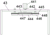
fig. 9 is a schematic side view of a second polishing assembly of the frame polishing device for door and window production according to the embodiment of the present application.
In the figure: 1. a support mechanism; 11. a base station; 12. a support assembly; 2. a feeding mechanism; 21. a support plate; 22. a lifting platform; 221. an electric push rod; 222. a lifting platform main body; 223. a sleeve; 224. inserting a rod; 23. a limiting component; 231. a fixing plate; 232. moving the plate; 2321. a groove; 2322. a telescopic rod; 3. a material conveying mechanism; 31. a support; 32. a pulley assembly; 33. a belt; 331. a convex strip; 4. a polishing mechanism; 41. a first frame; 42. a first grinding assembly; 421. a first motor; 422. a first rotating shaft; 423. a first turntable; 424. a first abrasive disc; 425. a second turntable; 426. a second sanding disc; 427. a first outer ring gear; 428. a second outer gear ring; 43. a second frame; 44. a second grinding assembly; 441. a second motor; 442. a second rotating shaft; 443. a third turntable; 444. a third polishing disc; 445. a fourth turntable; 446. a fourth sanding disc; 447. a third outer gear ring; 448. a fourth outer gear ring.
Detailed Description
In order to make the technical solutions better understood by those skilled in the art, the technical solutions in the embodiments of the present application will be clearly and completely described below with reference to the drawings in the embodiments of the present application, and it is obvious that the described embodiments are only partial embodiments of the present application, but not all embodiments. All other embodiments, which can be derived by a person skilled in the art from the embodiments given herein without making any creative effort, shall fall within the protection scope of the present application.
It should be noted that the terms "first," "second," and the like in the description and claims of this application and in the drawings described above are used for distinguishing between similar elements and not necessarily for describing a particular sequential or chronological order. It should be understood that the data so used may be interchanged under appropriate circumstances such that embodiments of the application described herein may be used. Furthermore, the terms "comprises," "comprising," and "having," and any variations thereof, are intended to cover a non-exclusive inclusion, such that a process, method, system, article, or apparatus that comprises a list of steps or elements is not necessarily limited to those steps or elements expressly listed, but may include other steps or elements not expressly listed or inherent to such process, method, article, or apparatus.
In this application, the terms "upper", "lower", "left", "right", "front", "rear", "top", "bottom", "inner", "outer", "middle", "vertical", "horizontal", "lateral", "longitudinal", and the like indicate orientations or positional relationships based on the orientations or positional relationships shown in the drawings. These terms are used primarily to better describe the present application and its embodiments, and are not used to limit the indicated devices, elements or components to a particular orientation or to be constructed and operated in a particular orientation.
Moreover, some of the above terms may be used to indicate other meanings besides the orientation or positional relationship, for example, the term "on" may also be used to indicate some kind of attachment or connection relationship in some cases. The specific meaning of these terms in this application will be understood by those of ordinary skill in the art as appropriate.
In addition, the term "plurality" shall mean two as well as more than two.
It should be noted that the embodiments and features of the embodiments in the present application may be combined with each other without conflict. The present application will be described in detail below with reference to the embodiments with reference to the attached drawings.
Example 1
Referring to fig. 1-9, the present application provides a frame polishing device for door and window production, which includes a supporting mechanism 1, a feeding mechanism 2, a material conveying mechanism 3 and a polishing mechanism 4. The feeding mechanism 2 is arranged on one side of the supporting mechanism 1 and used for assisting in feeding, the conveying mechanism 3 is arranged on the upper side of the supporting mechanism 1 and used for clamping and conveying workpieces, and the polishing mechanisms 4 are arranged on the upper side and the lower side of the conveying mechanism 3 and used for polishing the workpieces.
The support mechanism 1 comprises a base 11 and a support component 12; the supporting component 12 is fixedly connected to the lower side of the base 11;
the supporting component 12 is a vertical plate, and the upper side of the vertical plate is fixedly connected to the lower surface of the base 11.
The feeding mechanism 2 comprises a supporting plate 21, a lifting platform 22 and a limiting component 23, the supporting plate 21 is fixedly connected to the supporting component 12, the supporting plate 21 is horizontally arranged, the lifting platform 22 is installed on the supporting plate 21, and the limiting component 23 is installed on the upper side of the lifting platform 22;
the lifting platform 22 comprises an electric push rod 221, a lifting platform main body 222, a sleeve 223 and an insertion rod 224, wherein the base of the electric push rod 221 is fixedly connected to the support plate 21, the lifting platform main body 222 is fixedly connected to the upper end of the electric push rod 221, the sleeve 223 is fixedly connected to the support plate 21, the insertion rod 224 is fixedly connected to the lower surface of the lifting platform main body 222, and the lower end of the insertion rod 224 is slidably inserted into the sleeve 223.
The limiting assembly 23 comprises a fixing plate 231 and a moving plate 232, the fixing plate 231 is fixedly connected to the upper side of the lifting table 22, the moving plate 232 is installed on the upper side of the lifting table 22 through an adjusting support, and the moving plate 232 and the fixing plate 231 are arranged in parallel.
One side of the moving plate 232 is provided with a groove 2321, and the inside of the groove 2321 is provided with a telescopic rod 2322.
The fixed plate 231 and the moving plate 232 are respectively aligned with one side of the two groups of belts 33, and the window frame is placed between the fixed plate 231 and the moving plate 232, so that the window frame and the material conveying mechanism 3 can be aligned, and the feeding is convenient. After the position of the feeding mechanism 3 is adjusted, the position of the moving plate 232 needs to be adjusted correspondingly, and during adjustment, the telescopic rod 2322 is manually extended to the vicinity of the belt 33, so that the moving plate 232 and the belt can be aligned in an auxiliary manner.
The material conveying mechanism 3 comprises two groups of supports 31, two groups of belt pulley assemblies 32 and two groups of belts 33, wherein the two groups of supports 31 are arranged on the base station 11, the two groups of belt pulley assemblies 32 are respectively arranged on the two groups of supports 31, the two groups of belts 33 are respectively in transmission connection with the two groups of belt pulley assemblies 32, and convex strips 331 are arranged on the outer surfaces of the belts 33;
one set of mounts 31 is a fixed mount and the other set of mounts 31 is a moving mount. The distance between the two groups of belts 33 can be adjusted, so that the window frames with different sizes can be conveniently processed.
The grinding mechanism 4 comprises a first frame 41, a first grinding assembly 42, a second frame 43 and a second grinding assembly 44, wherein the first frame 41 and the second frame 43 are fixedly connected to the base 11, the first grinding assembly 42 is mounted on the first frame 41, and the second grinding assembly 44 is mounted on the second frame 43.
The horizontal height of the first frame 41 is smaller than the horizontal height of the belt 33;
the first grinding assembly 42 comprises a first motor 421, a first rotating shaft 422, a first rotating disc 423, a first grinding disc 424, a second rotating disc 425 and a second grinding disc 426, the first motor 421 is fixedly connected to the first frame 41, and the first rotating shaft 422 is fixedly connected to the output end of the first motor 421;
the first rotary disc 423 is fixedly connected to the upper end of the first rotary shaft 422, and the circumferential surface of the first rotary disc 423 is fixedly connected with a first outer gear ring 427;
the first abrasive disc 424 is fixedly attached to the first rotating disc 423;
the outer circle surface of the second rotary disc 425 is fixedly connected with a second outer gear ring 428, the second outer gear ring 428 is meshed with the first outer gear ring 427, and the second rotary disc 425 is rotatably connected to the first frame 41 through a rotating shaft;
a second sanding disc 426 is fixedly attached to the second turntable 425.
The horizontal height of the second frame 43 is greater than the horizontal height of the belt 33;
the second grinding assembly 44 comprises a second motor 441, a second rotating shaft 442, a third rotating disc 443, a third grinding disc 444, a fourth rotating disc 445 and a fourth grinding disc 446, the second motor 441 is fixedly connected to the second frame 43, and the second rotating shaft 442 is fixedly connected to the output end of the second motor 441;
the third rotary table 443 is fixedly connected to the upper end of the second rotary shaft 442, and a third outer ring gear 447 is fixedly connected to the circumferential surface of the third rotary table 443;
the third polishing disc 444 is fixedly connected to the third turntable 443;
the outer circle surface of the fourth turntable 445 is fixedly connected with a fourth external gear ring 448, the fourth external gear ring 448 is meshed with the third external gear ring 447, and the rotating shaft of the fourth turntable 445 is rotatably connected to the second frame 43 through a rotating shaft;
a fourth sanding disc 446 is fixedly attached to the fourth turntable 445.
The first sanding assemblies 42 are arranged in groups and the second sanding assemblies 44 are arranged in groups, the groups of first sanding assemblies 42 and the groups of second sanding assemblies 44 being staggered.
The working principle is as follows: when the feeding mechanism 2 is used, a workpiece to be processed is placed on the lifting platform 22, the window frame is pushed manually, feeding can be carried out, the lifting platform 22 is lifted once every time feeding is carried out, and therefore the window frame to be fed is flush with the conveying mechanism 3, and feeding is facilitated; promote forward can block the recess at window frame edge to the sand grip 331 of belt 33 on, belt 33 rotates, can carry the window frame, and two belts 33 press from both sides tight window frame, can steadily carry the window frame, set up two sets of polishing assemblies from top to bottom, can polish simultaneously to the upper and lower surface of window frame, have improved the efficiency of polishing, have saved the manual work.
The above description is only a preferred embodiment of the present application and is not intended to limit the present application, and various modifications and changes may be made by those skilled in the art. Any modification, equivalent replacement, improvement and the like made within the spirit and principle of the present application shall be included in the protection scope of the present application.
Claims (9)
1. The utility model provides a frame grinding device is used in door and window production which characterized in that includes:
a support mechanism (1), the support mechanism (1) comprising a base (11) and a support assembly (12); the supporting component (12) is fixedly connected to the lower side of the base platform (11);
the feeding mechanism (2) comprises a supporting plate (21), a lifting platform (22) and a limiting assembly (23), the supporting plate (21) is fixedly connected to the supporting assembly (12), the supporting plate (21) is horizontally arranged, the lifting platform (22) is installed on the supporting plate (21), and the limiting assembly (23) is installed on the upper side of the lifting platform (22);
the material conveying mechanism (3) comprises two groups of supports (31), two groups of belt pulley assemblies (32) and two groups of belts (33), the two groups of supports (31) are installed on the base station (11), the two groups of belt pulley assemblies (32) are installed on the two groups of supports (31) respectively, the two groups of belts (33) are in transmission connection with the two groups of belt pulley assemblies (32) respectively, and convex strips (331) are arranged on the outer surfaces of the belts (33);
grinding machanism (4), grinding machanism (4) are including first frame (41), first subassembly (42) of polishing, second frame (43) and the second subassembly (44) of polishing, first frame (41) and second frame (43) all fixed connection be in on base station (11), first subassembly (42) of polishing is installed on first frame (41), second subassembly (44) of polishing is installed on second frame (43).
2. The frame grinding device for door and window production as claimed in claim 1, wherein the support component (12) is a vertical plate, and the upper side of the vertical plate is fixedly connected to the lower surface of the base (11).
3. The frame grinding device for door and window production as claimed in claim 1, wherein the lifting table (22) comprises an electric push rod (221), a lifting table main body (222), a sleeve (223) and an insertion rod (224), a base of the electric push rod (221) is fixedly connected to the support plate (21), the lifting table main body (222) is fixedly connected to an upper end of the electric push rod (221), the sleeve (223) is fixedly connected to the support plate (21), the insertion rod (224) is fixedly connected to a lower surface of the lifting table main body (222), and a lower end of the insertion rod (224) is slidably inserted into the sleeve (223).
4. The frame polishing device for door and window production as claimed in claim 1, wherein the limiting assembly (23) comprises a fixed plate (231) and a moving plate (232), the fixed plate (231) is fixedly connected to the upper side of the lifting table (22), the moving plate (232) is mounted on the upper side of the lifting table (22) through an adjusting support, and the moving plate (232) and the fixed plate (231) are arranged in parallel.
5. The frame grinding device for door and window production as claimed in claim 4, wherein a groove (2321) is formed in one side of the moving plate (232), and a telescopic rod (2322) is arranged inside the groove (2321).
6. A jamb grinding device for door and window production according to claim 1, wherein one group of said holders (31) is a fixed holder, and the other group of said holders (31) is a movable holder.
7. The frame grinding device for door and window production as claimed in claim 1, wherein the horizontal height of the first frame (41) is smaller than the horizontal height of the belt (33);
the first grinding assembly (42) comprises a first motor (421), a first rotating shaft (422), a first rotating disc (423), a first grinding disc (424), a second rotating disc (425) and a second grinding disc (426), the first motor (421) is fixedly connected to the first frame (41), and the first rotating shaft (422) is fixedly connected to the output end of the first motor (421);
the first rotary disc (423) is fixedly connected to the upper end of the first rotating shaft (422), and the circumferential surface of the first rotary disc (423) is fixedly connected with a first outer gear ring (427);
the first polishing disc (424) is fixedly connected to the first rotating disc (423);
a second external gear ring (428) is fixedly connected to the outer circular surface of the second rotary disc (425), the second external gear ring (428) is meshed with the first external gear ring (427), and the second rotary disc (425) is rotatably connected to the first rack (41) through a rotating shaft;
the second polishing disc (426) is fixedly connected to the second rotating disc (425).
8. The frame grinding device for door and window production as claimed in claim 1, wherein the second frame (43) has a horizontal height greater than that of the belt (33);
the second grinding assembly (44) comprises a second motor (441), a second rotating shaft (442), a third rotating disc (443), a third grinding disc (444), a fourth rotating disc (445) and a fourth grinding disc (446), the second motor (441) is fixedly connected to a second frame (43), and the second rotating shaft (442) is fixedly connected to the output end of the second motor (441);
the third rotary table (443) is fixedly connected to the upper end of the second rotary shaft (442), and a third outer gear ring (447) is fixedly connected to the circumferential surface of the third rotary table (443);
the third polishing disc (444) is fixedly connected to the third rotating disc (443);
a fourth external gear ring (448) is fixedly connected to the outer circle surface of the fourth rotary disc (445), the fourth external gear ring (448) is meshed with the third external gear ring (447), and a rotating shaft of the fourth rotary disc (445) is rotatably connected to the second frame (43) through a rotating shaft;
the fourth polishing disc (446) is fixedly connected to the fourth turntable (445).
9. A jamb grinding apparatus for door and window production according to claim 1, wherein said first grinding unit (42) is provided with a plurality of sets, said second grinding unit (44) is provided with a plurality of sets, and said plurality of sets of first grinding units (42) and said plurality of sets of second grinding units (44) are staggered.
Priority Applications (1)
| Application Number | Priority Date | Filing Date | Title |
|---|---|---|---|
| CN202110059088.4A CN113798939B (en) | 2021-01-18 | 2021-01-18 | Frame grinding device is used in door and window production |
Applications Claiming Priority (1)
| Application Number | Priority Date | Filing Date | Title |
|---|---|---|---|
| CN202110059088.4A CN113798939B (en) | 2021-01-18 | 2021-01-18 | Frame grinding device is used in door and window production |
Publications (2)
| Publication Number | Publication Date |
|---|---|
| CN113798939A true CN113798939A (en) | 2021-12-17 |
| CN113798939B CN113798939B (en) | 2022-09-09 |
Family
ID=78892885
Family Applications (1)
| Application Number | Title | Priority Date | Filing Date |
|---|---|---|---|
| CN202110059088.4A Active CN113798939B (en) | 2021-01-18 | 2021-01-18 | Frame grinding device is used in door and window production |
Country Status (1)
| Country | Link |
|---|---|
| CN (1) | CN113798939B (en) |
Citations (5)
| Publication number | Priority date | Publication date | Assignee | Title |
|---|---|---|---|---|
| GB604406A (en) * | 1945-12-05 | 1948-07-02 | Leaderflush Ltd | Improvements in doors and similar articles of joinery and the means for and method of making the same |
| US3348342A (en) * | 1964-07-22 | 1967-10-24 | Joseph P Zachek | Finishing machine |
| CN202922712U (en) * | 2012-11-12 | 2013-05-08 | 东莞市南兴家具装备制造股份有限公司 | Automatic feeding mechanism of edge sealing machine |
| CN107553241A (en) * | 2017-10-25 | 2018-01-09 | 湖州欧贝得门业有限公司 | A kind of two-sided sander of plank |
| CN211661758U (en) * | 2020-01-20 | 2020-10-13 | 王炎彬 | Bamboo wood autoloading polisher |
-
2021
- 2021-01-18 CN CN202110059088.4A patent/CN113798939B/en active Active
Patent Citations (5)
| Publication number | Priority date | Publication date | Assignee | Title |
|---|---|---|---|---|
| GB604406A (en) * | 1945-12-05 | 1948-07-02 | Leaderflush Ltd | Improvements in doors and similar articles of joinery and the means for and method of making the same |
| US3348342A (en) * | 1964-07-22 | 1967-10-24 | Joseph P Zachek | Finishing machine |
| CN202922712U (en) * | 2012-11-12 | 2013-05-08 | 东莞市南兴家具装备制造股份有限公司 | Automatic feeding mechanism of edge sealing machine |
| CN107553241A (en) * | 2017-10-25 | 2018-01-09 | 湖州欧贝得门业有限公司 | A kind of two-sided sander of plank |
| CN211661758U (en) * | 2020-01-20 | 2020-10-13 | 王炎彬 | Bamboo wood autoloading polisher |
Also Published As
| Publication number | Publication date |
|---|---|
| CN113798939B (en) | 2022-09-09 |
Similar Documents
| Publication | Publication Date | Title |
|---|---|---|
| CN110977693A (en) | Air conditioner refrigeration accessory processing equipment | |
| CN111113219A (en) | Cell-phone shell revolving stage numerical control grinder | |
| CN113770902B (en) | Shaping device of ecological plate | |
| CN105033827A (en) | Full-automatic grinding and polishing device | |
| CN112008558A (en) | Automatic polishing equipment for machining special-shaped plates and working method thereof | |
| CN215092617U (en) | Efficient toughened glass edge grinding device | |
| CN113798939B (en) | Frame grinding device is used in door and window production | |
| CN113579893A (en) | Special-shaped corner connector processing equipment capable of grinding burrs | |
| CN108406539B (en) | Automatic go up unloading formula cell body grinding device from top to bottom | |
| CN108655904B (en) | Automatic groove body line of polishing about measurement formula | |
| CN205915142U (en) | Follow -on automatic cell phone case edging all -in -one | |
| CN108214120B (en) | Axe polishing robot | |
| CN113878461B (en) | Automatic special-shaped processing grinding machine for permanent magnetic ferrite | |
| CN216706971U (en) | Deburring machine for cold-rolled steel plate | |
| CN211277845U (en) | Cell-phone shell revolving stage numerical control grinder | |
| CN202399107U (en) | Edge grinding machine for mobile phone screens | |
| CN214419217U (en) | Automatic chamfering machine for ceramic ferrule | |
| CN211992280U (en) | Grinding machine | |
| CN114178951A (en) | Steel cutting surface equipment of polishing based on car processing | |
| CN212581940U (en) | Double-sided buffing equipment for artificial leather production | |
| CN117532454B (en) | Knitting needle tip polishing device | |
| CN216099070U (en) | Carrier band side cut device | |
| CN220699089U (en) | Metal electroplating front surface polishing treatment device | |
| CN220372866U (en) | Steel plate polishing and deburring device | |
| CN219562513U (en) | Automatic material taking mechanism of bearing grinding machine |
Legal Events
| Date | Code | Title | Description |
|---|---|---|---|
| PB01 | Publication | ||
| PB01 | Publication | ||
| SE01 | Entry into force of request for substantive examination | ||
| SE01 | Entry into force of request for substantive examination | ||
| GR01 | Patent grant | ||
| GR01 | Patent grant |