CN113798639B - Argon arc welding machine - Google Patents
Argon arc welding machine Download PDFInfo
- Publication number
- CN113798639B CN113798639B CN202111054306.1A CN202111054306A CN113798639B CN 113798639 B CN113798639 B CN 113798639B CN 202111054306 A CN202111054306 A CN 202111054306A CN 113798639 B CN113798639 B CN 113798639B
- Authority
- CN
- China
- Prior art keywords
- belt wheel
- telescopic rod
- tensioning
- argon arc
- belt
- Prior art date
- Legal status (The legal status is an assumption and is not a legal conclusion. Google has not performed a legal analysis and makes no representation as to the accuracy of the status listed.)
- Active
Links
Images

Classifications
-
- B—PERFORMING OPERATIONS; TRANSPORTING
- B23—MACHINE TOOLS; METAL-WORKING NOT OTHERWISE PROVIDED FOR
- B23K—SOLDERING OR UNSOLDERING; WELDING; CLADDING OR PLATING BY SOLDERING OR WELDING; CUTTING BY APPLYING HEAT LOCALLY, e.g. FLAME CUTTING; WORKING BY LASER BEAM
- B23K9/00—Arc welding or cutting
- B23K9/16—Arc welding or cutting making use of shielding gas
- B23K9/167—Arc welding or cutting making use of shielding gas and of a non-consumable electrode
-
- B—PERFORMING OPERATIONS; TRANSPORTING
- B23—MACHINE TOOLS; METAL-WORKING NOT OTHERWISE PROVIDED FOR
- B23K—SOLDERING OR UNSOLDERING; WELDING; CLADDING OR PLATING BY SOLDERING OR WELDING; CUTTING BY APPLYING HEAT LOCALLY, e.g. FLAME CUTTING; WORKING BY LASER BEAM
- B23K9/00—Arc welding or cutting
- B23K9/12—Automatic feeding or moving of electrodes or work for spot or seam welding or cutting
-
- B—PERFORMING OPERATIONS; TRANSPORTING
- B23—MACHINE TOOLS; METAL-WORKING NOT OTHERWISE PROVIDED FOR
- B23K—SOLDERING OR UNSOLDERING; WELDING; CLADDING OR PLATING BY SOLDERING OR WELDING; CUTTING BY APPLYING HEAT LOCALLY, e.g. FLAME CUTTING; WORKING BY LASER BEAM
- B23K9/00—Arc welding or cutting
- B23K9/24—Features related to electrodes
- B23K9/28—Supporting devices for electrodes
-
- B—PERFORMING OPERATIONS; TRANSPORTING
- B23—MACHINE TOOLS; METAL-WORKING NOT OTHERWISE PROVIDED FOR
- B23K—SOLDERING OR UNSOLDERING; WELDING; CLADDING OR PLATING BY SOLDERING OR WELDING; CUTTING BY APPLYING HEAT LOCALLY, e.g. FLAME CUTTING; WORKING BY LASER BEAM
- B23K9/00—Arc welding or cutting
- B23K9/32—Accessories
Abstract
The invention relates to the technical field of industrial welding equipment, in particular to an argon arc welding machine. An argon arc welding machine comprises a frame body, wherein a driving mechanism is arranged at the top end of the frame body, a motor is arranged outside the top end of the frame body, a tensioning mechanism is connected inside the driving mechanism, and a workbench is fixedly connected to the lower end of the frame body; when the argon arc welding machine is used, the tungsten needle is eccentrically arranged on the turntable, so that a human hand can be simulated to swing left and right during rotation, and the tungsten needle can rotate along with the turntable to avoid the tungsten needle tip from being easily agglomerated.
Description
Technical Field
The invention relates to the technical field of industrial welding equipment, in particular to an argon arc welding machine.
Background
Argon arc welding in the prior art is generally performed manually, when argon arc welding is performed on stainless steel pipes of various sizes, manual welding is adopted, although the welding has the advantages that the welding is not limited by shapes, the welding efficiency is low, the welding quality is unstable, the welding quality is directly hooked with the proficiency of workers, the product quality is unbalanced, and the tip part of a tungsten needle is easy to agglomerate in the welding process, so that the stability of electric arc generation is influenced.
The prior art also discloses argon arc welding machines, wherein two support rods are erected on a frame body, a bottom plate is fixed on each support rod, two parallel sliding seats are fixed on the bottom plate, a sliding groove is formed in the middle of each sliding seat, a sliding block is matched on each sliding groove, a bearing seat is connected on each sliding block, a sliding shaft is connected between the two bearing seats, a belt wheel is arranged in the middle of each sliding shaft, one end of each sliding shaft extends out of each sliding block, a welding gun fixing rod is fixedly connected to the tail end of each sliding shaft, a welding gun clamping block is fixed to the lower end of each welding gun fixing rod, and a welding gun is fixed to each welding gun clamping block; one end of the bottom plate is provided with a cylinder seat, one end of the cylinder seat is fixedly provided with a cylinder, the cylinder extends out of an extension shaft, the extension shaft is connected with a rack, the rack is matched with a belt wheel on a sliding shaft, and the rack pushes the sliding shaft to slide along a sliding groove on the sliding seat; the support body on connect a workstation bottom plate, a cooperation lifter plate on the workstation bottom plate, four edges of lifter plate be equipped with the connecting seat, be connected with the connecting axle on the connecting seat, a connecting axle both ends cooperation regulating plate, a fixed workstation on the regulating plate, a fixed work piece holder on the workstation, work piece holder and welder cooperate, welder carries out welding treatment to the work piece on the work piece holder under the sliding shaft drives.
The inventor finds that heat concentration at one end or a local position can be caused by welding along the same direction in the welding process, so that the workpiece is easy to deform, and in addition, the tip of the tungsten needle is easy to agglomerate in the argon arc welding process, so that the stability of electric arc generation is influenced.
Disclosure of Invention
The invention aims to solve the following problems:
1. welding along the same direction in the argon arc welding process can cause heat concentration at one end or a local position, and cause workpiece deformation;
2. in the existing argon arc welding process, the tip part of the tungsten needle is easy to agglomerate, and the stability of electric arc generation is influenced.
In order to achieve the purpose, the invention adopts the following technical scheme:
an argon arc welding machine comprises a frame body, wherein a driving mechanism is arranged at the top end of the frame body, a motor is arranged outside the top end of the frame body, a tensioning mechanism is connected inside the driving mechanism, and a workbench is fixedly connected to the lower end of the frame body;
the driving mechanism comprises a top plate, a fixed driving mechanism which can be better fixed at the lower end of the frame body by utilizing the top plate, a two-way thread lead screw is arranged in the top plate, a first slider and a second slider are arranged at two ends of the two-way thread lead screw, the rotation of the two-way thread lead screw can be converted into the relative movement of the first slider and the second slider by setting the two-way thread lead screw, a first belt wheel is coaxially connected outside the first slider, a second belt wheel is coaxially connected outside the second slider, the first slider and the second slider can move in opposite directions and simultaneously drive the first belt wheel and the second belt wheel to move in opposite directions by setting the first belt wheel and the second belt wheel, a first telescopic rod and a second telescopic rod are coaxially hinged to two sides of the first belt wheel respectively, a third telescopic rod and a fourth telescopic rod are coaxially hinged to two sides of the second belt wheel respectively, the first telescopic rod and the third telescopic rod are simultaneously coaxially hinged to the third belt wheel, the second telescopic rod and the fourth telescopic rod are simultaneously coaxially hinged to the fourth belt wheel, the first belt wheel, the second belt wheel, and the third belt wheel and the fourth belt can be driven by the belt synchronously.
As a further improvement of the belt tensioning device, the tensioning mechanism comprises a fixing block, a tensioning wheel is connected to the fixing block, a tensioning screw rod is arranged outside the tensioning wheel, the belt can be tensioned by screwing the tensioning screw rod after the belt is used for a period of time through the tensioning screw rod, so that the normal work of the driving mechanism is guaranteed, the tensioning wheel is matched with the belt, and the tensioning screw rod penetrates through a fourth telescopic rod.
As a further improvement of the invention, welding guns are arranged on the lower surfaces of the first belt wheel, the second belt wheel, the third belt wheel and the fourth belt wheel, tungsten needles are arranged in the welding guns, and the four welding guns can work simultaneously to realize the welding of workpieces, so that the welding efficiency is greatly improved. Preferably, the tungsten needle is eccentrically arranged compared with the rotation centers of the first belt wheel, the second belt wheel, the third belt wheel and the fourth belt wheel, and the situation that a hand swings the tungsten needle left and right during welding operation can be simulated through the eccentrically arranged tungsten needle; preferably, one of the first belt wheel, the second belt wheel, the third belt wheel and the fourth belt wheel is connected with a motor, and the motor can be used for realizing the rapid rotation of the tungsten needle, so that the conglomeration on the tungsten needle can be thrown out, and the cleaning of the conglomeration is realized. According to different welding requirements, the tungsten needle can be cleaned while being welded, the tungsten needle can be quickly lifted away from a workpiece after the tungsten needle is subjected to agglomeration, and the agglomeration is cleaned by utilizing quick rotation. When necessary, the invention can be added with shielding to avoid the conglomeration and throwing out to hurt people.
As a further improvement of the invention, the lower end of the workbench is connected with a lifting plate, the lower end of the lifting plate is matched with an air cylinder, the extending end of the air cylinder is fixedly connected with the lifting plate, the air cylinder can drive the lifting plate to move up and down in the pushing process, and the effect of lifting the workbench up and down can be realized.
As a further improvement of the invention, a melting tank is arranged in the workbench, a cooling fan is arranged at one end of the melting tank, and the melting tank and the cooling fan are arranged to quickly cool the workpiece after welding, thereby improving the cooling efficiency of the workpiece.
As a further improvement of the invention, the worktable is of a Y-shaped structure, and the Y-shaped structure is arranged to reduce the contact between the workpiece and the worktable and avoid the workpiece from being bonded together.
As a further improvement of the invention, the output end of the motor is connected with the bidirectional threaded lead screw, the bidirectional threaded lead screw is rotated by connecting the output end of the motor with the bidirectional threaded lead screw, and the moving directions of the first sliding block and the second sliding block on the bidirectional threaded lead screw can be changed by adjusting the steering of the motor.
As a further improvement of the invention, the first telescopic rod, the second telescopic rod, the third telescopic rod and the fourth telescopic rod respectively comprise a convex rod and a concave rod, the convex rod is matched with the concave rod, the convex rod is fixedly connected with the concave rod through a bolt, and the lengths of the first telescopic rod, the second telescopic rod, the third telescopic rod and the fourth telescopic rod can be adjusted better by adjusting the length of the convex rod inserted into the concave rod.
As a further improvement of the invention, the belt is made of elastic materials, and the first telescopic rod, the second telescopic rod, the third telescopic rod and the fourth telescopic rod which are made of elastic materials and can be well adapted and adjusted are adopted. Compared with the prior art, the invention provides an argon arc welding machine, which has the following beneficial effects:
1. the argon arc welding machine can be in opposite directions during welding, so that heat can be prevented from being locally concentrated, and a workpiece can be kept flat after being welded.
2. When the tungsten needle rotating device is used, the tungsten needle is eccentrically arranged on the rotating disc, so that the left-right swinging of a hand can be simulated during rotation, and meanwhile, the tungsten needle can eccentrically rotate along with the rotating disc to avoid the pointed part of the tungsten needle from being easily agglomerated.
The parts which are not involved in the device are the same as or can be realized by the prior art, and the driving mechanism is arranged, so that the problem that heat concentration at one end or a local position is caused by welding along the same direction in the manual welding process is solved.
Drawings
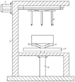
FIG. 1 is a cross-sectional view of an argon arc welding machine according to the present invention;
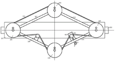
FIG. 2 is a schematic structural diagram of a driving mechanism of an argon arc welding machine according to the present invention;
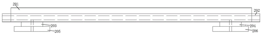
FIG. 3 is a schematic structural diagram of a top plate of an argon arc welding machine according to the present invention;
FIG. 4 is a side view of a driving mechanism of an argon arc welding machine according to the present invention;
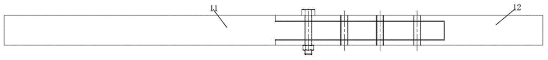
fig. 5 is a schematic structural view of a first telescopic rod of an argon arc welding machine according to the present invention.
In the figure: the device comprises a frame body 1, a driving mechanism 2, a top plate 201, a bidirectional threaded screw 202, a first slider 203, a second slider 204, a first belt wheel 205, a second belt wheel 206, a first telescopic rod 207, a second telescopic rod 208, a third belt wheel 209, a third telescopic rod 210, a fourth telescopic rod 211, a fourth belt wheel 212, a belt 213, a motor 3, a tensioning mechanism 4, a fixed block 401, a tensioning wheel 402, a tensioning screw 403, a workbench 5, a welding gun 6, a tungsten needle 7, a lifting plate 8, an air cylinder 9, a melting tank 10, a convex rod 11 and a concave rod 12.
Detailed Description
The technical solutions in the embodiments of the present invention will be clearly and completely described below with reference to the drawings in the embodiments of the present invention, and it is obvious that the described embodiments are only a part of the embodiments of the present invention, and not all of the embodiments.
The technical solutions in the embodiments of the present invention will be clearly and completely described below with reference to the drawings in the embodiments of the present invention, and it is obvious that the described embodiments are only a part of the embodiments of the present invention, and not all of the embodiments.
In the description of the present invention, it is to be understood that the terms "upper", "lower", "front", "rear", "left", "right", "top", "bottom", "inner", "outer", and the like, are used in the orientations and positional relationships indicated in the drawings, which are based on the orientations and positional relationships indicated in the drawings, and are used for convenience of description and simplicity of description, but do not indicate or imply that the devices or elements referred to must have a particular orientation, be constructed and operated in a particular orientation, and thus, are not to be construed as limiting the present invention.
Referring to fig. 1-5, the argon arc welding machine comprises a frame body 1, wherein a driving mechanism 2 is arranged at the top end of the frame body 1, a motor 3 is arranged outside the top end of the frame body 1, a tensioning mechanism 4 is connected inside the driving mechanism 2, and a working table 5 is fixedly connected to the lower end of the frame body 1;
the driving mechanism 2 comprises a top plate 201, the top plate 201 is fixed on the fixed driving mechanism 2 which can be well fixed at the lower end of the frame body 1, a bidirectional threaded lead screw 202 is arranged in the top plate 201, a first slider 203 and a second slider 204 are arranged at two ends of the bidirectional threaded lead screw 202, the rotation of the bidirectional threaded lead screw 202 can be converted into the relative movement of the first slider 203 and the second slider 204 by arranging the bidirectional threaded lead screw 202, a first belt pulley 205 is coaxially connected outside the first slider 203, a second belt pulley 206 is coaxially connected outside the second slider 204, the first slider 203 and the second slider 204 can move in opposite directions and simultaneously drive the first belt pulley 205 and the second belt pulley 206 to move in opposite directions by arranging the first belt pulley 205 and the second belt pulley 206, two sides of the first belt pulley 205 are respectively and coaxially hinged with a first telescopic rod 207 and a second telescopic rod 208, two sides of the second belt pulley 206 are respectively and coaxially hinged with a third telescopic rod 210 and a fourth telescopic rod 211, the first telescopic rod 207 and the third telescopic rod 210 are simultaneously and coaxially hinged with a third belt pulley 209, the second belt pulley 211 and the fourth belt pulley 213 are synchronously installed on the third belt pulley 209, the fourth belt pulley 213 and the fourth belt pulley 213, and the fourth belt pulley 213 are installed on the outer belt pulley 209, and the outer belt pulley 213, and the belt pulley 213 are synchronously installed.
As a further improvement of the present invention, the tensioning mechanism 4 includes a fixing block 401, a tensioning wheel 402 is connected to the fixing block 401, a tensioning screw 403 is provided outside the tensioning wheel 402, the tensioning screw 403 can tension the belt 213 by screwing the tensioning screw 403 after the belt 213 is used for a period of time, so as to ensure that the driving mechanism 2 works normally, the tensioning wheel 402 is matched with the belt 213, and the tensioning screw 403 passes through the fourth telescopic rod 211.
As a further improvement of the invention, the welding guns 6 are arranged on the lower surfaces of the first belt pulley 205, the second belt pulley 206, the third belt pulley 209 and the fourth belt pulley 212, the tungsten needle 7 is arranged in the welding guns 6, and the four welding guns 6 can work simultaneously and cooperate with the welding wire to weld the workpiece, so that the welding efficiency is greatly improved. Preferably, the tungsten needle 7 is eccentrically disposed with respect to the rotational centers of the first pulley 205, the second pulley 206, the third pulley 209, and the fourth pulley 212, and the tungsten needle 7 eccentrically disposed can simulate a situation in which a human hand swings the tungsten needle 7 left and right during a welding operation; preferably, one of the first pulley 205, the second pulley 206, the third pulley 209 and the fourth pulley 212 is connected to a motor, and the motor can be used to realize the rapid rotation of the tungsten needle 7, so as to facilitate throwing out the lumps on the tungsten needle 7 and realize the cleaning of the lumps. According to different welding requirements, the tungsten needle 7 can be cleaned while being welded, and also can be quickly lifted away from a workpiece after being agglomerated, and then the agglomerated is cleaned by utilizing quick rotation. When necessary, the invention can be added with shielding to avoid the conglomeration and throwing out to hurt people.
As a further improvement of the invention, the lower end of the workbench 5 is connected with a lifting plate 8, the lower end of the lifting plate 8 is matched with a cylinder 9, the extending end of the cylinder 9 is fixedly connected with the lifting plate 8, the cylinder 9 can drive the lifting plate 8 to move up and down in the pushing process by arranging the cylinder 9, and the effect that the workbench 5 can be lifted up and down can be realized.
As a further improvement of the invention, a melting tank 10 is arranged in the workbench 5, a cooling fan is arranged at one end of the melting tank 10, and the workpiece can be rapidly cooled by air after being welded by arranging the melting tank 10 and the cooling fan, so that the heat dissipation efficiency of the workpiece is improved.
As a further improvement of the invention, the worktable 5 is of a Y-shaped structure, and the Y-shaped structure is arranged to reduce the contact between the workpiece and the worktable 5 and avoid the adhesion together.
As a further improvement of the present invention, the output end of the motor 3 is connected to the two-way threaded lead screw 202, the two-way threaded lead screw 202 is rotated by connecting the output end of the motor 3 to the two-way threaded lead screw 202, and the moving directions of the first slider 203 and the second slider 204 on the two-way threaded lead screw 202 can be changed by adjusting the rotation direction of the motor 3.
As a further improvement of the present invention, each of the first telescopic rod 207, the second telescopic rod 208, the third telescopic rod 210 and the fourth telescopic rod 211 comprises a convex rod 11 and a concave rod 12, the convex rod 11 is matched with the concave rod 12, the convex rod 11 is fixedly connected with the concave rod 12 through a bolt, and the lengths of the first telescopic rod 207, the second telescopic rod 208, the third telescopic rod 210 and the fourth telescopic rod 211 can be adjusted by adjusting the length of the convex rod 11 inserted into the concave rod 12.
As a further improvement of the present invention, the belt 213 is made of an elastic material, and the first telescopic rod 207, the second telescopic rod 208, the third telescopic rod 210 and the fourth telescopic rod 211 which are made of elastic materials and can be adjusted in a better matching manner are adopted.
The working principle is as follows: by starting the motor 3, the output end of the motor 3 is rotated, and meanwhile, the bidirectional threaded lead screw 202 is driven to rotate, at the moment, the first slider 203 drives the first belt pulley 205, the second slider 204 drives the second belt pulley 206 to move towards the middle position of the bidirectional threaded lead screw 202, and meanwhile, the third belt pulley 209 and the fourth belt pulley 212 are driven by the belt 213 to move away from the top plate 201, by switching the rotation direction of the output shaft of the motor 3, the argon arc welding machine can move in opposite directions during welding, and the inward concentration of welding heat during workpiece welding can be avoided, so that the workpiece can keep better flatness after being welded, meanwhile, the first belt pulley 205, the second belt pulley 206, the third belt pulley 209 and the fourth belt pulley 212 can drive the welding gun 6 which is eccentrically arranged correspondingly to rotate when rotating, the tungsten needle 7 in the welding gun 6 eccentrically rotates and simultaneously rotates, the eccentric arrangement of the tungsten needle 7 is utilized, so that the left-right swing of a human hand can be simulated during rotation, and the tungsten needle 7 can rotate along with the turntable to avoid the easy agglomeration of the tip of the tungsten needle 7.
The above description is only for the preferred embodiment of the present invention, but the scope of the present invention is not limited thereto, and any person skilled in the art should be considered as the technical solutions and the inventive concepts of the present invention within the technical scope of the present invention.
Claims (4)
1. An argon arc welding machine comprises a frame body (1), wherein a driving mechanism (2) is arranged at the top end of the frame body (1), a motor (3) is arranged outside the top end of the frame body (1), a tensioning mechanism (4) is connected inside the driving mechanism (2), and a workbench (5) is fixedly connected to the lower end of the frame body (1);
the method is characterized in that: the driving mechanism (2) comprises a top plate (201), a bidirectional threaded lead screw (202) is arranged in the top plate (201), a first sliding block (203) and a second sliding block (204) are arranged at two ends of the bidirectional threaded lead screw (202), a first belt wheel (205) is coaxially connected outside the first sliding block (203), a second belt wheel (206) is coaxially connected outside the second sliding block (204), a first telescopic rod (207) and a second telescopic rod (208) are coaxially hinged to two sides of the first belt wheel (205) respectively, a third telescopic rod (210) and a fourth telescopic rod (211) are coaxially hinged to two sides of the second belt wheel (206) respectively, the first telescopic rod (207) and the third telescopic rod (210) are coaxially hinged to a third belt wheel (209) simultaneously, the second telescopic rod (208) and the fourth telescopic rod (211) are coaxially hinged to a fourth belt wheel (212) simultaneously, and a belt (213) is arranged outside the first belt wheel (205), the second belt wheel (206), the third belt wheel (209) and the fourth belt wheel (212);
the tensioning mechanism (4) comprises a fixing block (401), a tensioning wheel (402) is connected to the fixing block (401), a tensioning screw (403) is arranged outside the tensioning wheel (402), the tensioning wheel (402) is matched with the belt (213), and the tensioning screw (403) penetrates through a fourth telescopic rod (211);
welding guns (6) are arranged on the lower surfaces of the first belt wheel (205), the second belt wheel (206), the third belt wheel (209) and the fourth belt wheel (212), and tungsten needles (7) are arranged inside the welding guns (6);
the tungsten needle (7) is eccentrically disposed with respect to the rotation centers of the first pulley (205), the second pulley (206), the third pulley (209), and the fourth pulley (212).
2. An argon arc welding machine according to claim 1, characterized in that: workstation (5) lower extreme is connected with lifter plate (8), and lifter plate (8) lower extreme cooperation has cylinder (9), and the end that stretches out and lifter plate (8) fixed connection of cylinder (9) can make cylinder (9) drive lifter plate (8) up-and-down motion at the promotion in-process through setting up cylinder (9), can realize the effect of workstation (5) oscilaltion.
3. An argon arc welding machine according to claim 1, characterized in that: a melting tank (10) is arranged in the workbench (5), and a cooling fan is arranged at one end of the melting tank (10).
4. An argon arc welding machine according to claim 1, characterized in that: first telescopic link (207), second telescopic link (208), third telescopic link (210) and fourth telescopic link (211) all include nose bar (11) and concave pole (12), nose bar (11) and concave pole (12) cooperate, nose bar (11) and concave pole (12) are through bolt fixed connection, insert the length of the better regulation first telescopic link (207), second telescopic link (208), third telescopic link (210) and the length of fourth telescopic link (211) of concave pole (12) through adjusting nose bar (11).
Priority Applications (1)
| Application Number | Priority Date | Filing Date | Title |
|---|---|---|---|
| CN202111054306.1A CN113798639B (en) | 2021-09-09 | 2021-09-09 | Argon arc welding machine |
Applications Claiming Priority (1)
| Application Number | Priority Date | Filing Date | Title |
|---|---|---|---|
| CN202111054306.1A CN113798639B (en) | 2021-09-09 | 2021-09-09 | Argon arc welding machine |
Publications (2)
| Publication Number | Publication Date |
|---|---|
| CN113798639A CN113798639A (en) | 2021-12-17 |
| CN113798639B true CN113798639B (en) | 2022-11-29 |
Family
ID=78894977
Family Applications (1)
| Application Number | Title | Priority Date | Filing Date |
|---|---|---|---|
| CN202111054306.1A Active CN113798639B (en) | 2021-09-09 | 2021-09-09 | Argon arc welding machine |
Country Status (1)
| Country | Link |
|---|---|
| CN (1) | CN113798639B (en) |
Citations (6)
| Publication number | Priority date | Publication date | Assignee | Title |
|---|---|---|---|---|
| CN104014908A (en) * | 2014-06-03 | 2014-09-03 | 丹阳市长江汽车部件有限公司 | Equipment for continuously welding circular welds |
| WO2018103081A1 (en) * | 2016-12-09 | 2018-06-14 | 冯庆柱 | Laser composite welding device |
| CN208843142U (en) * | 2018-10-08 | 2019-05-10 | 青岛固德物流系统工程有限公司 | A kind of lower floating Guiding wheel structure of Expansion belt conveyor |
| CN110549154A (en) * | 2019-09-10 | 2019-12-10 | 陕西闹闹馨馨知识产权服务有限公司 | Building board cutting device and working method thereof |
| CN210154797U (en) * | 2019-08-13 | 2020-03-17 | 广州市旭创机电设备有限公司 | Belt wheel detection device |
| CN111250830A (en) * | 2018-12-03 | 2020-06-09 | 广州长胜机电有限公司 | Argon arc welding machine |
-
2021
- 2021-09-09 CN CN202111054306.1A patent/CN113798639B/en active Active
Patent Citations (6)
| Publication number | Priority date | Publication date | Assignee | Title |
|---|---|---|---|---|
| CN104014908A (en) * | 2014-06-03 | 2014-09-03 | 丹阳市长江汽车部件有限公司 | Equipment for continuously welding circular welds |
| WO2018103081A1 (en) * | 2016-12-09 | 2018-06-14 | 冯庆柱 | Laser composite welding device |
| CN208843142U (en) * | 2018-10-08 | 2019-05-10 | 青岛固德物流系统工程有限公司 | A kind of lower floating Guiding wheel structure of Expansion belt conveyor |
| CN111250830A (en) * | 2018-12-03 | 2020-06-09 | 广州长胜机电有限公司 | Argon arc welding machine |
| CN210154797U (en) * | 2019-08-13 | 2020-03-17 | 广州市旭创机电设备有限公司 | Belt wheel detection device |
| CN110549154A (en) * | 2019-09-10 | 2019-12-10 | 陕西闹闹馨馨知识产权服务有限公司 | Building board cutting device and working method thereof |
Also Published As
| Publication number | Publication date |
|---|---|
| CN113798639A (en) | 2021-12-17 |
Similar Documents
| Publication | Publication Date | Title |
|---|---|---|
| CN208556434U (en) | A kind of automatic welder of head and heat-dissipating pipe | |
| CN206898546U (en) | A kind of vertical circular seam welding machine | |
| CN209773695U (en) | Circular seam welding equipment for steel cylinder | |
| CN207681694U (en) | A kind of stifled automatic soldering device of axis | |
| CN109332967B (en) | Triaxial real-time tracking welding structure and freezer welding equipment thereof | |
| CN112518182A (en) | Full-automatic welding device | |
| CN216780660U (en) | Automatic location laser-beam welding machine | |
| CN113714632A (en) | Circular saw blade laser welding equipment | |
| CN113798639B (en) | Argon arc welding machine | |
| CN212470277U (en) | Prevent fire door production and use door frame welding equipment | |
| CN113351978A (en) | High-frequency welding device for preventing cylindrical part from moving during high-efficiency heat treatment | |
| CN216882510U (en) | Welding alignment device of rivet welding machine | |
| CN202356798U (en) | Shell crack welding machine of locomotive capacitor | |
| CN206605185U (en) | A kind of movement in a curve servo slide table | |
| CN217096424U (en) | Direct-current seam welder for bidirectionally adsorbing machined parts | |
| CN212705245U (en) | Valve core girth welding device of precision valve | |
| CN211727907U (en) | Adjustable positioning type laser welding machine | |
| CN212122162U (en) | Multi-degree-of-freedom welding robot | |
| CN211708022U (en) | Forging equipment for hardware production | |
| CN208374539U (en) | A kind of welding machine | |
| CN209867637U (en) | Gas shielded welding frock | |
| CN219900635U (en) | Friction welding equipment for part machining | |
| CN210967678U (en) | Weldment angle adjusting mechanism for automatic welding machine | |
| CN219310481U (en) | Welding set is used in boats and ships rail repair | |
| CN216177856U (en) | Automatic large-scale work piece automatic weld equipment of loading |
Legal Events
| Date | Code | Title | Description |
|---|---|---|---|
| PB01 | Publication | ||
| PB01 | Publication | ||
| SE01 | Entry into force of request for substantive examination | ||
| SE01 | Entry into force of request for substantive examination | ||
| TA01 | Transfer of patent application right |
Effective date of registration: 20221114 Address after: 510700 A201, 38 Sangtian 1st Road, Huangpu District, Guangzhou City, Guangdong Province Applicant after: Guangzhou Welding King Electric Technology Co.,Ltd. Address before: 210000 room 703, building 12, Jinma Licheng East District, No. 111, Aoti street, Jianye District, Nanjing, Jiangsu Province Applicant before: Chen Shujian |
|
| TA01 | Transfer of patent application right | ||
| GR01 | Patent grant | ||
| GR01 | Patent grant |