CN113732379A - Copying planing tool rest and plate planing method - Google Patents
Copying planing tool rest and plate planing method Download PDFInfo
- Publication number
- CN113732379A CN113732379A CN202111047609.0A CN202111047609A CN113732379A CN 113732379 A CN113732379 A CN 113732379A CN 202111047609 A CN202111047609 A CN 202111047609A CN 113732379 A CN113732379 A CN 113732379A
- Authority
- CN
- China
- Prior art keywords
- tool rest
- planing
- tool
- horizontal
- vertical
- Prior art date
- Legal status (The legal status is an assumption and is not a legal conclusion. Google has not performed a legal analysis and makes no representation as to the accuracy of the status listed.)
- Pending
Links
Images

Classifications
-
- B—PERFORMING OPERATIONS; TRANSPORTING
- B23—MACHINE TOOLS; METAL-WORKING NOT OTHERWISE PROVIDED FOR
- B23D—PLANING; SLOTTING; SHEARING; BROACHING; SAWING; FILING; SCRAPING; LIKE OPERATIONS FOR WORKING METAL BY REMOVING MATERIAL, NOT OTHERWISE PROVIDED FOR
- B23D7/00—Planing or slotting machines characterised only by constructional features of particular parts
- B23D7/06—Planing or slotting machines characterised only by constructional features of particular parts of tool-carrying arrangements
Abstract
The invention discloses a profiling planing tool rest and a plate planing method, and the profiling planing tool rest comprises a tool rest horizontal sliding seat and a tool rest fixing seat which are Contraband-shaped, wherein two tool rest plates are arranged in parallel up and down in an opening of the tool rest horizontal sliding seat, a tool holder and a vertical guide wheel are arranged on each of the two tool rest plates, planing tools on the two tool holder plates are arranged oppositely, vertical elastic elements are arranged on the sides, which are opposite, of the two tool rest plates respectively, a horizontal guide wheel is arranged between the two tool rest plates, the tool rest horizontal sliding seat is arranged in the opening of the tool rest fixing seat, and a horizontal elastic element is arranged between the tool rest fixing seat and the tool rest horizontal sliding seat. This knife rest can make the planer tool laminate the composite sheet steel surface automatically, along the composite sheet side and keep one section stable distance and planing degree of depth with it, digs the steel sheet in succession along the composite sheet surface, can effectively guarantee the stability of composite sheet steel planing degree of depth, reduces the loss of core resource, improves composite sheet planing work efficiency and degree of automation.
Description
Technical Field
The invention relates to the technical field of cutter tools, in particular to a copying planing tool rest and a plate planing method.
Background
The metal composite plate is a composite material formed by utilizing various composite technologies to realize metallurgical bonding of metals with different properties on an interface. The existing composite board is formed by metallurgically combining a core board, an upper layer of thin steel sheet, a lower layer of thin steel sheet and a peripheral frame with thick periphery through high-temperature hot rolling. Since the core of such composite panels is completely covered by the outer steel jacket formed by the skin and the peripheral frame, the outer steel jacket must be stripped to obtain the inner core. However, the cladding hot rolling process of the composite plate is performed under the conditions of high temperature and large deformation, the outer steel jacket of the composite plate is tightly attached to the inner core plate, and the resource of the inner core plate is very precious, so it is a difficult task to remove the outer steel jacket of the composite plate to take out the inner core plate and reduce the damage of the resource of the core plate as much as possible.
At present, no special equipment for stripping the outer steel jacket of the composite board exists, and the whole work of stripping the outer steel jacket of the composite board is mainly completed manually. Wherein, one step in the work of peeling off the outer steel jacket of the composite board is to dig the surface steel sheet along the edge of the inner core board at the long edge steel sheet of the composite board. Since core board resources are very precious, it is desirable to minimize damage to core board resources when planing surface steel skin. In conventional composite slab planing operations, which are performed by hand with conventional planing tools, the work requires both planing along the surface skin and the peripheral frame side path. Because the upper surface and the lower surface of the composite board are warped, the widths of the core boards in the same composite board are consistent, the total width of the composite board is consistent, and the side edges of the composite board are also bent to a certain extent. The traditional tool rest can not achieve the purpose of profiling, is difficult to enable the tool bit of the planer to be tightly attached to the surface of the steel sheet of the composite board, can not ensure that the surface of the steel sheet of the composite board is completely and continuously planed, and can cause the phenomenon that the steel sheet on the surface of the composite board can not be planed completely or the planed depth of a raised area is too large to damage an internal core plate. Moreover, the traditional working mode of planing the composite board is high in labor intensity, low in automation degree and high in operation difficulty.
Disclosure of Invention
The invention aims to: in order to solve the problems that the conventional tool rest cannot stably plane the composite board steel sheet along with the side edge and the upper and lower surface edge paths of the composite board in the process of planing the steel sheet by the composite board, so that the planing depth is unstable, the automation degree is low and the operability is poor, the copying planing tool rest and the plate planing method are provided, the tool rest can enable a cutter to automatically attach to the surface of the composite board steel sheet, a stable distance and a planing depth are kept along the edge of the composite board and the edge of the composite board, the steel sheet is continuously planed along the surface of the composite board, the stability of the planing depth of the composite board steel sheet can be effectively guaranteed, the loss of core board resources is reduced, and the planing working efficiency and the automation degree of the composite board are improved.
In order to achieve the purpose, the invention adopts the technical scheme that:
a profiling planing tool rest comprises a tool rest horizontal sliding seat and a tool rest fixing seat which are Contraband-shaped, wherein two tool rest plates are arranged in parallel up and down in an opening of the tool rest horizontal sliding seat, a tool holder and vertical guide wheels are arranged on the two tool rest plates, planing tools on the two tool holder plates are arranged oppositely, the two vertical guide wheels are used for walking along the upper surface and the lower surface of a composite plate respectively, vertical elastic elements are arranged on one sides of the two tool rest plates, which are deviated from each other, respectively, and enable the two tool rest plates to slide along vertical straight lines, a horizontal guide wheel is arranged between the two tool rest plates and used for walking along the side surface of the composite plate, the tool rest horizontal sliding seat is arranged in the opening of the tool rest fixing seat, a horizontal elastic element is arranged between the tool rest fixing seat and the tool rest horizontal sliding seat, and the horizontal elastic element enables the tool rest horizontal sliding seat to slide along a horizontal straight line.
When the composite board is warped up and down, one group of vertical elastic elements can be compressed, and the other group of vertical elastic elements can be extended, so that the two tool rest plates synchronously slide along the vertical straight line, and the profiling planing in the vertical direction is realized; when the side edge of the composite board is bent, the horizontal sliding seat of the tool rest slides along a horizontal straight line under the telescopic action of the horizontal elastic element, so that the horizontal guide wheel is always attached to the side edge of the composite board, and the profiling planing in the horizontal direction is realized; this knife rest can make the planer tool laminate the composite sheet steel surface automatically, along the composite sheet side and keep one section stable distance and planing degree of depth with it, digs the steel sheet in succession along the composite sheet surface, can effectively guarantee the stability of composite sheet steel planing degree of depth, reduces the loss of core resource, improves composite sheet planing work efficiency and degree of automation.
As a preferable scheme of the invention, a thickness adjusting spring is further arranged between the two tool rest plates, and the thickness adjusting spring separates the two tool rest plates, so that the distance between the cutting edges of the two planing tools is smaller than the thickness of the composite plate and the two planing tools are not in contact with each other. After the technical scheme is adopted, under the non-working state, the vertical guide wheels enable the two tool rest plates to be close to the middle under the extrusion of the upper and lower groups of vertical elastic elements, the thickness adjusting springs enable the two tool rest plates to keep a certain distance, the distance between the cutting edges of the two planing tools is smaller than the safety distance of the minimum plate thickness of the composite plate, the two planing tools are not in contact, and the upper planing tool and the lower planing tool are prevented from colliding with the tools to damage the tools.
As a preferable scheme of the invention, a plurality of vertical guide rods are arranged in parallel in the opening of the horizontal sliding seat of the tool rest, and each vertical guide rod penetrates through two tool rest plates. So set up for two tool rest boards carry out synchronous slip from top to bottom along perpendicular guide bar at the during operation.
As a preferable scheme of the present invention, the horizontal guide wheel and the thickness adjustment spring are respectively sleeved on the vertical guide rod, so that when the composite board warps up and down, the horizontal guide wheel and the thickness adjustment spring can slide up and down along the vertical guide rod.
As a preferable scheme of the invention, the outer wall of the horizontal guide wheel is provided with an annular groove, and the width of the annular groove is greater than the thickness of the composite plate. Therefore, the side edge of the composite board can enter the annular groove, and the horizontal guide wheel is driven to slide along the vertical guide rod when the composite board warps up and down.
As a preferable scheme of the present invention, the vertical elastic elements are a plurality of vertical profile springs arranged in parallel, and the vertical profile springs are respectively sleeved on the vertical guide rods.
As a preferable scheme of the invention, the tool rest plate is provided with a mounting hole, one end of the tool holder far away from the planer tool is fixed in the mounting hole, and a cushion block is further arranged in the mounting hole and used for adjusting the distance between the tool holder and the horizontal guide wheel. Because the width of different composite boards may not be consistent with the width of the internal core board, a cushion block capable of changing the thickness of the composite board is arranged at the position of the tool holder to adjust the distance between the tool holder and the horizontal guide wheel, thereby achieving the purpose of adjusting the planing position of the planer tool and enabling the planing mode to be applicable to planing different composite boards.
As a preferable scheme of the present invention, the tool rest plate is provided with a guide wheel support, and the vertical guide wheel is rotatably mounted on the guide wheel support.
As a preferable scheme of the invention, the horizontal elastic elements are a plurality of horizontal profiling springs arranged in parallel, and the horizontal profiling springs are respectively sleeved on horizontal guide rods preset on the horizontal sliding seat of the tool rest.
A method for planing steel sheets on the surface of a composite plate by utilizing the profiling planing tool rest comprises the following steps:
firstly, fixing a composite board on a workbench;
secondly, arranging profiling planing tool holders on two sides of the composite plate, and spreading the two tool holder plates to enable the composite plate to enter the position where the planing tool is located;
and step three, the two profiling planing tool rests synchronously move along the length direction of the composite board, the two tool rest plates slide along a vertical straight line through the vertical elastic elements, the two vertical guide wheels respectively move along the upper surface and the lower surface of the composite board, and the horizontal sliding seat of the tool rest slides along a horizontal straight line through the horizontal elastic elements, so that the horizontal guide wheels move along the side surfaces of the composite board.
According to the method, the vertical elastic element and the horizontal elastic element are adopted to realize the copying function of the tool rest in the vertical direction and the horizontal direction, the problem that the traditional tool rest cannot cut along the edge path of the composite board with warping and lateral bending is solved, the situations that the traditional composite board planing depth is unstable and planing is incomplete are solved, the traditional working mode of manually planing the composite board is replaced by the copying planing tool rest, the traditional mode of manually adjusting the cutting position and the cutting depth of the composite board is solved, manual labor force is liberated, the automation degree of the planing work of the composite board is greatly improved, copying planing tools are symmetrically arranged on two sides of the composite board, the planing work of two sides of the composite board is completed simultaneously, the planing work efficiency of the composite board is improved, and meanwhile, the copying planing tool rest and the planing method can also be applied to copying and planing grooves on common board type workpieces.
In summary, due to the adoption of the technical scheme, the invention has the beneficial effects that:
when the composite board is warped up and down, one group of vertical elastic elements can be compressed, and the other group of vertical elastic elements can be extended, so that the two tool rest plates synchronously slide along the vertical straight line, and the profiling planing in the vertical direction is realized; when the side edge of the composite board is bent, the horizontal sliding seat of the tool rest slides along a horizontal straight line under the telescopic action of the horizontal elastic element, so that the horizontal guide wheel is always attached to the side edge of the composite board, and the profiling planing in the horizontal direction is realized; this knife rest can make the planer tool laminate the composite sheet steel surface automatically, along the composite sheet side and keep one section stable distance and planing degree of depth with it, digs the steel sheet in succession along the composite sheet surface, can effectively guarantee the stability of composite sheet steel planing degree of depth, reduces the loss of core resource, improves composite sheet planing work efficiency and degree of automation.
Drawings
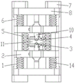
FIG. 1 is a front view of a profile planing tool holder according to the present invention.
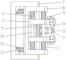
Fig. 2 is a left side view of fig. 1.
Figure 3 is a perspective view of a profile planing tool holder according to the present invention.
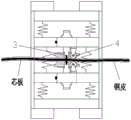
Fig. 4 is a schematic view of a vertical profile in the present invention.
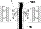
Fig. 5 is a schematic view of a horizontal copying in the present invention.
The labels in the figure are: 1-lower vertical profiling spring, 2-tool rest plate, 3-planer tool, 4-vertical guide wheel, 5-thickness adjusting spring, 6-upper vertical profiling spring, 7-tool rest fixing seat, 8-tool rest horizontal sliding seat, 9-cushion block, 10-tool rest, 11-horizontal guide wheel, 12-horizontal profiling spring, 13-horizontal guide rod and 14-vertical guide rod.
Detailed Description
The present invention will be described in detail below with reference to the accompanying drawings.
In order to make the objects, technical solutions and advantages of the present invention more apparent, the present invention is described in further detail below with reference to the accompanying drawings and embodiments. It should be understood that the specific embodiments described herein are merely illustrative of the invention and are not intended to limit the invention.
Example 1
The present embodiment provides a profile planing tool holder;
as shown in fig. 1 to 5, the copying planing tool rest in this embodiment includes a tool rest horizontal sliding seat 8 and a tool rest fixing seat 7, which are shaped like Contraband, two tool rest plates 2 are arranged in parallel up and down in an opening of the tool rest horizontal sliding seat 8, a tool holder 10 and a vertical guide wheel 4 are arranged on each of the two tool rest plates 2, planing tools 3 on the two tool holder plates 10 are arranged oppositely, the two vertical guide wheels 4 are used for respectively walking along upper and lower surfaces of a composite plate, vertical elastic elements are respectively arranged on opposite sides of the two tool rest plates 2, the vertical elastic elements enable the two tool rest plates 2 to slide along vertical straight lines, a horizontal guide wheel 11 is arranged between the two tool rest plates 2, the horizontal guide wheel 11 is used for walking along a side surface of the composite plate, the tool rest horizontal sliding seat 8 is arranged in an opening of the tool rest fixing seat 7, a horizontal elastic element is arranged between the tool rest fixing seat 7 and the tool rest horizontal sliding seat 8, the horizontal elastic element makes the tool rest horizontal sliding seat 8 slide along a horizontal straight line.
When the composite board is warped up and down, one group of vertical elastic elements can be compressed, and the other group of vertical elastic elements can be extended, so that the two tool rest plates synchronously slide along the vertical straight line, and the profiling planing in the vertical direction is realized; when the side edge of the composite board is bent, the horizontal sliding seat of the tool rest slides along a horizontal straight line under the telescopic action of the horizontal elastic element, so that the horizontal guide wheel is always attached to the side edge of the composite board, and the profiling planing in the horizontal direction is realized; this knife rest can make the planer tool hug closely the composite sheet steel surface automatically, and along the composite sheet side and keep one section stable distance and planing degree of depth with it, dig the steel sheet in succession along the composite sheet surface, can effectively guarantee the stability of composite sheet steel sheet planing degree of depth, reduce the loss of core resource, improve composite sheet planing work efficiency and degree of automation.
In this embodiment, a thickness adjusting spring 5 is further disposed between the two tool rest plates 2, and the thickness adjusting spring 5 separates the two tool rest plates 2, so that the distance between the cutting edges of the two planing tools 3 is smaller than the thickness of the composite plate and does not contact each other. After the technical scheme is adopted, under the non-working state, the vertical guide wheels enable the two tool rest plates to be close to the middle under the extrusion of the upper and lower groups of vertical elastic elements, the thickness adjusting springs enable the two tool rest plates to keep a certain distance, the distance between the cutting edges of the two planing tools is smaller than the safety distance of the minimum plate thickness of the composite plate, the two planing tools are not in contact, and the upper planing tool and the lower planing tool are prevented from colliding with the tools to damage the tools.
In this embodiment, a plurality of vertical guide rods 14 are arranged in parallel in the opening of the horizontal sliding seat 8 of the tool rest, and each vertical guide rod 14 penetrates through two tool rest plates 2. So set up for two tool rest boards carry out synchronous slip from top to bottom along perpendicular guide bar at the during operation.
In this embodiment, the horizontal guide wheel 11 and the thickness adjusting spring 5 are respectively sleeved on the vertical guide rod 14, so that when the composite board warps up and down, the horizontal guide wheel and the thickness adjusting spring can slide up and down along the vertical guide rod.
In this embodiment, an annular groove is formed in the outer wall of the horizontal guide wheel 11, and the width of the annular groove is greater than the thickness of the composite plate. Therefore, the side edge of the composite board can enter the annular groove, and the horizontal guide wheel is driven to slide along the vertical guide rod when the composite board warps up and down.
In this embodiment, the vertical elastic elements are a plurality of vertical profiling springs arranged in parallel, wherein an upper vertical profiling spring 6 is located above the rack plate, a lower vertical profiling spring 1 is located below the rack plate, and the upper vertical profiling spring 6 and the lower vertical profiling spring 1 are respectively sleeved on the vertical guide rod 14.
In this embodiment, a mounting hole is formed in the tool rest plate 2, one end of the tool holder 10, which is far away from the planer tool 3, is fixed in the mounting hole, and a cushion block 9 is further arranged in the mounting hole, wherein the cushion block 9 is used for adjusting the distance between the tool holder 10 and the horizontal guide wheel 11. Because the width of different composite boards may not be consistent with the width of the internal core board, a cushion block capable of changing the thickness of the composite board is arranged at the position of the tool holder to adjust the distance between the tool holder and the horizontal guide wheel, thereby achieving the purpose of adjusting the planing position of the planer tool and enabling the planing mode to be applicable to planing different composite boards.
In this embodiment, be equipped with the leading wheel support on the tool rest board 2, perpendicular leading wheel 4 rotationally installs on the leading wheel support for when horizontal leading wheel rolled the walking along the composite sheet side, perpendicular leading wheel can be followed the rolling walking of composite sheet surface skin.
In this embodiment, the horizontal elastic elements are a plurality of horizontal profiling springs 12 arranged in parallel, the horizontal profiling springs 12 are respectively sleeved on horizontal guide rods 13 preset on the horizontal sliding seat 8 of the tool holder, and the horizontal guide rods 13 are slidably arranged in through holes formed in the tool holder fixing seat 7.
Specifically, the profile modeling planing tool rest controls the displacement of the tool in the vertical direction by an upper vertical profile modeling spring 6 and a lower vertical profile modeling spring 1 which are distributed in an up-down symmetrical mode, and a vertical guide wheel 4 and a planing tool 3 are fixed on the tool rest plate 2. In the planing process, the vertical guide wheel 4 is tightly attached to the upper surface and the lower surface of the composite plate under the pressure of the upper vertical profiling spring 6 and the lower vertical profiling spring 1, and the displacement of the planer tool 3 in the vertical direction is controlled; the horizontal guide wheel 11 is tightly attached to the side face of the composite plate under the action of the horizontal profiling spring 12, the horizontal displacement of the cutter is controlled, and the cutting position of the planer tool is changed by changing the thickness of the cushion block 9.
Under the non-working state, the vertical guide wheel 4 enables the two tool rest plates 2 to be close to the middle under the extrusion of the upper vertical profiling spring 6 and the lower vertical profiling spring 1, the thickness adjusting spring 5 enables a certain distance to be kept between the two tool rest plates 2, the distance between the cutting edges of the two planing tools is smaller than the safety distance of the minimum plate thickness of the composite plate, the two planing tools are not in contact, and the upper planing tool and the lower planing tool cannot collide with the tools to damage the tools.
Under operating condition, the composite sheet is fixed on corresponding station, and the shaping planing knife rest of composite sheet both sides moves along the long direction of composite sheet board, accomplishes planing work simultaneously, and at first, two upper and lower perpendicular leading wheels 4 contact the composite sheet upper and lower surface, and the perpendicular contour spring 6 of top and the perpendicular contour spring 1 of below are compressed, and two tool rest boards 2 are strutted, and horizontal leading wheel 11 also contacts the composite sheet side simultaneously, and horizontal contour spring 12 is also compressed, 8 corresponding movements of knife rest horizontal sliding seat. The tool rest continues to move forwards, and the planer tool begins to plane and cut steel sheets on the upper surface and the lower surface of the composite board.
When the edge of the composite board warps upwards, the vertical guide wheel 4 above the composite board has a section of upward displacement under the upward extrusion force of the composite board, so that the upper vertical profile spring 6 is compressed upwards, and meanwhile, the vertical guide wheel 4 below the composite board has an upward displacement, so that the lower vertical profile spring 1 extends upwards. Because the vertical profiling spring originally has certain prestress, the shrinkage of the upper vertical profiling spring 6 is equal to the elongation of the lower vertical profiling spring 1, so that the distance between the two tool rest plates is still unchanged, and the purpose of profiling and planing the tool rest in the vertical direction is achieved; the action principle of the composite board is the same when the edge of the composite board is warped downwards, and a vertical profiling principle diagram is shown in fig. 4.
When the side edge of the composite board is bent outwards, the horizontal guide wheel 11 moves outwards under the extrusion of the side edge of the composite board in the horizontal direction, so that the horizontal profiling spring 12 is compressed, and the outward movement of the horizontal guide wheel 11 drives the horizontal sliding seat 8 of the tool rest to move outwards; and the horizontal guide wheel on the other side moves inwards under the extension action of the horizontal copying spring 12 and still clings to the edge of the side edge of the composite board, and the inward movement of the horizontal guide wheel 11 drives the whole horizontal sliding seat 8 to move inwards, so that the aim of copying in the horizontal direction is fulfilled. The principle of action is the same when the side edges of the composite plate are bent inwards, and a horizontal copying principle diagram is shown in figure 5.
Example 2
This example provides a method of planing a skin of a composite panel using the profiling planing tool holder of example 1, comprising the steps of:
firstly, fixing a composite board on a workbench;
secondly, arranging profiling planing tool holders on two sides of the composite plate, and spreading the two tool holder plates to enable the composite plate to enter the position where the planing tool is located;
and step three, the two profiling planing tool rests synchronously move along the length direction of the composite board, the two tool rest plates slide along a vertical straight line through the vertical elastic elements, the two vertical guide wheels respectively move along the upper surface and the lower surface of the composite board, and the horizontal sliding seat of the tool rest slides along a horizontal straight line through the horizontal elastic elements, so that the horizontal guide wheels move along the side surfaces of the composite board.
According to the method, the vertical elastic element and the horizontal elastic element are adopted to realize the copying function of the tool rest in the vertical direction and the horizontal direction, the problem that the traditional tool rest cannot cut along the edge path of the composite board with warping and lateral bending is solved, the situations that the traditional composite board planing depth is unstable and planing is incomplete are solved, the copying planing tool rest replaces the working mode of manually planing the composite board, the traditional mode of manually adjusting the cutting position and the cutting depth of the composite board is solved, manual labor force is liberated, the automation degree of the planing work of the composite board is greatly improved, copying planing tools are symmetrically arranged on two sides of the composite board, the planing work of two sides of the composite board is completed simultaneously, and the planing work efficiency of the composite board is improved.
The above description is only for the purpose of illustrating the preferred embodiments of the present invention and is not to be construed as limiting the invention, and any modifications, equivalents and improvements made within the spirit of the present invention are intended to be included within the scope of the present invention.
Claims (10)
1. A profiling planing tool rest is characterized by comprising a tool rest horizontal sliding seat and a tool rest fixing seat which are Contraband-shaped, two tool rest plates are arranged in parallel up and down in an opening of the tool rest horizontal sliding seat, a tool holder and a vertical guide wheel are arranged on each of the two tool rest plates, planing tools on the two tool holders are oppositely arranged, the two vertical guide wheels are used for respectively walking along the upper surface and the lower surface of the composite plate, vertical elastic elements are respectively arranged on the sides of the two tool rest plates, which are far away from each other, and enable the two tool rest plates to slide along vertical straight lines, a horizontal guide wheel is arranged between the two tool rest plates and used for walking along the side surface of the composite plate, the tool rest horizontal sliding seat is arranged in the opening of the tool rest fixing seat, a horizontal elastic element is arranged between the tool rest fixing seat and the tool rest horizontal sliding seat, and the horizontal elastic element enables the tool rest horizontal sliding seat to slide along a horizontal straight line.
2. The copying shave tool holder of claim 1, further comprising a thickness adjustment spring disposed between the two holder plates, the thickness adjustment spring spacing the two holder plates apart and keeping the two planer cutting edges spaced less than the thickness of the composite sheet and out of contact with each other.
3. The copying planing tool head of claim 2 wherein a plurality of vertical guide bars are disposed in parallel in the opening of the horizontal sliding block of the tool head, and each vertical guide bar extends through two tool head plates.
4. The contour planing tool holder according to claim 3 wherein said horizontal guide wheel and said thickness adjustment spring are respectively sleeved on vertical guide bars.
5. The contour planing tool holder according to claim 4 wherein said horizontal guide wheel has an annular groove in the outer wall thereof, said annular groove having a width greater than the thickness of the composite sheet.
6. The profile planing tool head according to claim 5 wherein said vertical resilient member is a plurality of parallel vertical profile springs which are respectively mounted on said vertical guide bars.
7. The copying planing tool holder of any of claims 1 to 6 wherein the holder plate is provided with mounting holes and the end of the holder remote from the planing tool is secured in the mounting holes and the mounting holes are provided with spacer blocks for adjusting the distance of the holder relative to the horizontal guide wheels.
8. The contour planing tool holder according to claim 7 wherein said holder plate is provided with a guide wheel support and said vertical guide wheel is rotatably mounted on said guide wheel support.
9. The profile planing tool head according to any of the claims 1 to 6, wherein said horizontal elastic elements are a plurality of horizontal profile springs arranged in parallel, and said horizontal profile springs are respectively sleeved on horizontal guide rods preset on the horizontal sliding seat of the tool head.
10. A method for planing a sheet metal, wherein the profiling planing tool holder according to any one of claims 1 to 9 is used for planing a steel sheet on the surface of a composite plate, comprising the following steps:
firstly, fixing a composite board on a workbench;
secondly, arranging profiling planing tool holders on two sides of the composite plate, and spreading the two tool holder plates to enable the composite plate to enter the position where the planing tool is located;
and step three, the two profiling planing tool rests synchronously move along the length direction of the composite board, the two tool rest plates slide along a vertical straight line through the vertical elastic elements, the two vertical guide wheels respectively move along the upper surface and the lower surface of the composite board, and the horizontal sliding seat of the tool rest slides along a horizontal straight line through the horizontal elastic elements, so that the horizontal guide wheels move along the side surfaces of the composite board.
Priority Applications (1)
| Application Number | Priority Date | Filing Date | Title |
|---|---|---|---|
| CN202111047609.0A CN113732379A (en) | 2021-09-08 | 2021-09-08 | Copying planing tool rest and plate planing method |
Applications Claiming Priority (1)
| Application Number | Priority Date | Filing Date | Title |
|---|---|---|---|
| CN202111047609.0A CN113732379A (en) | 2021-09-08 | 2021-09-08 | Copying planing tool rest and plate planing method |
Publications (1)
| Publication Number | Publication Date |
|---|---|
| CN113732379A true CN113732379A (en) | 2021-12-03 |
Family
ID=78736865
Family Applications (1)
| Application Number | Title | Priority Date | Filing Date |
|---|---|---|---|
| CN202111047609.0A Pending CN113732379A (en) | 2021-09-08 | 2021-09-08 | Copying planing tool rest and plate planing method |
Country Status (1)
| Country | Link |
|---|---|
| CN (1) | CN113732379A (en) |
Citations (13)
| Publication number | Priority date | Publication date | Assignee | Title |
|---|---|---|---|---|
| GB130013A (en) * | 1917-12-15 | 1919-07-31 | George Ratcliffe | Improved Metal Planing or Trimming Machine. |
| CN201410581Y (en) * | 2009-06-15 | 2010-02-24 | 江苏玉龙钢管股份有限公司 | Edge planing machine for steel plate |
| CN201415282Y (en) * | 2009-01-24 | 2010-03-03 | 番禺珠江钢管有限公司 | Floating edge planer |
| CN102371386A (en) * | 2010-08-10 | 2012-03-14 | 北京隆盛泰科石油管科技有限公司 | Edge planer for steel plate |
| CN103386697A (en) * | 2013-08-22 | 2013-11-13 | 江旭阳 | Bamboo cane transporting structure being suitable for bamboo cane sliver-milling all-in-one machine |
| CN205415878U (en) * | 2016-03-18 | 2016-08-03 | 宋燚 | Adjustable four sides planing wood machine about cutter |
| CN208772614U (en) * | 2018-08-22 | 2019-04-23 | 河南欧科塑业股份有限公司 | A kind of high molecular weight polyethylene board material automatic chamfering device |
| CN209408698U (en) * | 2018-11-30 | 2019-09-20 | 连云港君盛包装制品有限公司 | A kind of novel two-sided woodworking thicknesser |
| CN210755438U (en) * | 2019-03-01 | 2020-06-16 | 天津塞维拉电梯轨道系统有限公司 | Centering conveying device for T-shaped track |
| CN211360811U (en) * | 2019-11-29 | 2020-08-28 | 安徽威亚机械制造有限公司 | Keyway planer knife rest and keyway planer that contains this knife rest |
| CN212019552U (en) * | 2020-03-31 | 2020-11-27 | 天津华通铝业有限公司 | Multi-station groove planer for aluminum veneer processing |
| CN212471821U (en) * | 2020-04-28 | 2021-02-05 | 崇仁县实达木业有限公司 | High-precision double-sided thicknessing device for processing environment-friendly plates |
| CN214136428U (en) * | 2020-10-15 | 2021-09-07 | 江西飞宇竹材股份有限公司 | Two-sided planing processing equipment of bamboo chip |
-
2021
- 2021-09-08 CN CN202111047609.0A patent/CN113732379A/en active Pending
Patent Citations (13)
| Publication number | Priority date | Publication date | Assignee | Title |
|---|---|---|---|---|
| GB130013A (en) * | 1917-12-15 | 1919-07-31 | George Ratcliffe | Improved Metal Planing or Trimming Machine. |
| CN201415282Y (en) * | 2009-01-24 | 2010-03-03 | 番禺珠江钢管有限公司 | Floating edge planer |
| CN201410581Y (en) * | 2009-06-15 | 2010-02-24 | 江苏玉龙钢管股份有限公司 | Edge planing machine for steel plate |
| CN102371386A (en) * | 2010-08-10 | 2012-03-14 | 北京隆盛泰科石油管科技有限公司 | Edge planer for steel plate |
| CN103386697A (en) * | 2013-08-22 | 2013-11-13 | 江旭阳 | Bamboo cane transporting structure being suitable for bamboo cane sliver-milling all-in-one machine |
| CN205415878U (en) * | 2016-03-18 | 2016-08-03 | 宋燚 | Adjustable four sides planing wood machine about cutter |
| CN208772614U (en) * | 2018-08-22 | 2019-04-23 | 河南欧科塑业股份有限公司 | A kind of high molecular weight polyethylene board material automatic chamfering device |
| CN209408698U (en) * | 2018-11-30 | 2019-09-20 | 连云港君盛包装制品有限公司 | A kind of novel two-sided woodworking thicknesser |
| CN210755438U (en) * | 2019-03-01 | 2020-06-16 | 天津塞维拉电梯轨道系统有限公司 | Centering conveying device for T-shaped track |
| CN211360811U (en) * | 2019-11-29 | 2020-08-28 | 安徽威亚机械制造有限公司 | Keyway planer knife rest and keyway planer that contains this knife rest |
| CN212019552U (en) * | 2020-03-31 | 2020-11-27 | 天津华通铝业有限公司 | Multi-station groove planer for aluminum veneer processing |
| CN212471821U (en) * | 2020-04-28 | 2021-02-05 | 崇仁县实达木业有限公司 | High-precision double-sided thicknessing device for processing environment-friendly plates |
| CN214136428U (en) * | 2020-10-15 | 2021-09-07 | 江西飞宇竹材股份有限公司 | Two-sided planing processing equipment of bamboo chip |
Non-Patent Citations (1)
| Title |
|---|
| 傅万四;沈毅;周建波;: "竹质OSB刨片机设计与试验", 农业机械学报, no. 01, pages 95 - 100 * |
Similar Documents
| Publication | Publication Date | Title |
|---|---|---|
| CN219151857U (en) | Metal plate grooving and laser cutting machine with movable working table panel | |
| CN105127304A (en) | Blanking stamping die | |
| CN113732379A (en) | Copying planing tool rest and plate planing method | |
| EP1786579B1 (en) | Machine with multifunction hydraulic head for bending and forming metallic sheets | |
| CN109648339B (en) | Plate forming and cutting integrated equipment | |
| CN103639264A (en) | Piercing die and punching-cutting machining method | |
| CN216632215U (en) | 45-degree double-station cutting die for section bar | |
| CN211415479U (en) | Combined gang drill | |
| CN210936728U (en) | Two-way side cutting die for heat shield | |
| CN103418677B (en) | Cut bending and molding all-in-one and its implementation | |
| CN209970168U (en) | Battery tray clamping mechanism of battery tray continuous production line | |
| CN214557718U (en) | T-shaped guide rail machining centering cutter | |
| CN218225068U (en) | Movable working table plate for metal plate grooving and laser cutting machine | |
| CN218946628U (en) | Gantry type grooving and laser cutting integrated machine with clearance structure | |
| CN211277064U (en) | Section bar laser cutting machine workstation | |
| CN212246764U (en) | Glass lead scribing table | |
| CN218611903U (en) | Slotting mechanism of multi-head slot planer and horizontal multi-head slot planer | |
| CN217251986U (en) | Workpiece rotary cutting device | |
| CN215091387U (en) | Laser carving machine with lengthened plate | |
| CN217433918U (en) | Plate cutting machine | |
| CN209811727U (en) | Porous metal cutting device | |
| CN211247922U (en) | Cable support unloads a stamping die | |
| CN211516296U (en) | High-efficient door facings door frame groover | |
| CN219402554U (en) | Die cutting device for channel steel | |
| CN217914161U (en) | Positioning device of cutting machine |
Legal Events
| Date | Code | Title | Description |
|---|---|---|---|
| PB01 | Publication | ||
| PB01 | Publication | ||
| SE01 | Entry into force of request for substantive examination | ||
| SE01 | Entry into force of request for substantive examination |