CN113710128A - Combustion chamber for particulate grill - Google Patents
Combustion chamber for particulate grill Download PDFInfo
- Publication number
- CN113710128A CN113710128A CN202080032060.5A CN202080032060A CN113710128A CN 113710128 A CN113710128 A CN 113710128A CN 202080032060 A CN202080032060 A CN 202080032060A CN 113710128 A CN113710128 A CN 113710128A
- Authority
- CN
- China
- Prior art keywords
- chamber
- wall
- inner chamber
- cooking
- plenum
- Prior art date
- Legal status (The legal status is an assumption and is not a legal conclusion. Google has not performed a legal analysis and makes no representation as to the accuracy of the status listed.)
- Pending
Links
Images


Classifications
-
- F—MECHANICAL ENGINEERING; LIGHTING; HEATING; WEAPONS; BLASTING
- F24—HEATING; RANGES; VENTILATING
- F24B—DOMESTIC STOVES OR RANGES FOR SOLID FUELS; IMPLEMENTS FOR USE IN CONNECTION WITH STOVES OR RANGES
- F24B1/00—Stoves or ranges
- F24B1/02—Closed stoves
- F24B1/024—Closed stoves for pulverulent fuels
-
- A—HUMAN NECESSITIES
- A47—FURNITURE; DOMESTIC ARTICLES OR APPLIANCES; COFFEE MILLS; SPICE MILLS; SUCTION CLEANERS IN GENERAL
- A47J—KITCHEN EQUIPMENT; COFFEE MILLS; SPICE MILLS; APPARATUS FOR MAKING BEVERAGES
- A47J37/00—Baking; Roasting; Grilling; Frying
- A47J37/06—Roasters; Grills; Sandwich grills
- A47J37/07—Roasting devices for outdoor use; Barbecues
- A47J37/0704—Roasting devices for outdoor use; Barbecues with horizontal fire box
-
- A—HUMAN NECESSITIES
- A47—FURNITURE; DOMESTIC ARTICLES OR APPLIANCES; COFFEE MILLS; SPICE MILLS; SUCTION CLEANERS IN GENERAL
- A47J—KITCHEN EQUIPMENT; COFFEE MILLS; SPICE MILLS; APPARATUS FOR MAKING BEVERAGES
- A47J37/00—Baking; Roasting; Grilling; Frying
- A47J37/06—Roasters; Grills; Sandwich grills
- A47J37/07—Roasting devices for outdoor use; Barbecues
- A47J37/0786—Accessories
-
- F—MECHANICAL ENGINEERING; LIGHTING; HEATING; WEAPONS; BLASTING
- F23—COMBUSTION APPARATUS; COMBUSTION PROCESSES
- F23B—METHODS OR APPARATUS FOR COMBUSTION USING ONLY SOLID FUEL
- F23B1/00—Combustion apparatus using only lump fuel
- F23B1/30—Combustion apparatus using only lump fuel characterised by the form of combustion chamber
- F23B1/36—Combustion apparatus using only lump fuel characterised by the form of combustion chamber shaft-type
-
- F—MECHANICAL ENGINEERING; LIGHTING; HEATING; WEAPONS; BLASTING
- F23—COMBUSTION APPARATUS; COMBUSTION PROCESSES
- F23B—METHODS OR APPARATUS FOR COMBUSTION USING ONLY SOLID FUEL
- F23B50/00—Combustion apparatus in which the fuel is fed into or through the combustion zone by gravity, e.g. from a fuel storage situated above the combustion zone
- F23B50/12—Combustion apparatus in which the fuel is fed into or through the combustion zone by gravity, e.g. from a fuel storage situated above the combustion zone the fuel being fed to the combustion zone by free fall or by sliding along inclined surfaces, e.g. from a conveyor terminating above the fuel bed
-
- F—MECHANICAL ENGINEERING; LIGHTING; HEATING; WEAPONS; BLASTING
- F23—COMBUSTION APPARATUS; COMBUSTION PROCESSES
- F23B—METHODS OR APPARATUS FOR COMBUSTION USING ONLY SOLID FUEL
- F23B60/00—Combustion apparatus in which the fuel burns essentially without moving
- F23B60/02—Combustion apparatus in which the fuel burns essentially without moving with combustion air supplied through a grate
-
- F—MECHANICAL ENGINEERING; LIGHTING; HEATING; WEAPONS; BLASTING
- F23—COMBUSTION APPARATUS; COMBUSTION PROCESSES
- F23G—CREMATION FURNACES; CONSUMING WASTE PRODUCTS BY COMBUSTION
- F23G7/00—Incinerators or other apparatus for consuming industrial waste, e.g. chemicals
- F23G7/10—Incinerators or other apparatus for consuming industrial waste, e.g. chemicals of field or garden waste or biomasses
- F23G7/105—Incinerators or other apparatus for consuming industrial waste, e.g. chemicals of field or garden waste or biomasses of wood waste
-
- F—MECHANICAL ENGINEERING; LIGHTING; HEATING; WEAPONS; BLASTING
- F24—HEATING; RANGES; VENTILATING
- F24B—DOMESTIC STOVES OR RANGES FOR SOLID FUELS; IMPLEMENTS FOR USE IN CONNECTION WITH STOVES OR RANGES
- F24B13/00—Details solely applicable to stoves or ranges burning solid fuels
- F24B13/02—Arrangement or mountings of fire-grate assemblies; Arrangement or mountings of linings for fire-boxes, e.g. fire-backs
-
- F—MECHANICAL ENGINEERING; LIGHTING; HEATING; WEAPONS; BLASTING
- F24—HEATING; RANGES; VENTILATING
- F24B—DOMESTIC STOVES OR RANGES FOR SOLID FUELS; IMPLEMENTS FOR USE IN CONNECTION WITH STOVES OR RANGES
- F24B5/00—Combustion-air or flue-gas circulation in or around stoves or ranges
- F24B5/02—Combustion-air or flue-gas circulation in or around stoves or ranges in or around stoves
- F24B5/021—Combustion-air or flue-gas circulation in or around stoves or ranges in or around stoves combustion-air circulation
-
- F—MECHANICAL ENGINEERING; LIGHTING; HEATING; WEAPONS; BLASTING
- F23—COMBUSTION APPARATUS; COMBUSTION PROCESSES
- F23B—METHODS OR APPARATUS FOR COMBUSTION USING ONLY SOLID FUEL
- F23B1/00—Combustion apparatus using only lump fuel
- F23B1/30—Combustion apparatus using only lump fuel characterised by the form of combustion chamber
- F23B1/38—Combustion apparatus using only lump fuel characterised by the form of combustion chamber for combustion of peat, sawdust, or pulverulent fuel on a grate or other fuel support
-
- F—MECHANICAL ENGINEERING; LIGHTING; HEATING; WEAPONS; BLASTING
- F23—COMBUSTION APPARATUS; COMBUSTION PROCESSES
- F23G—CREMATION FURNACES; CONSUMING WASTE PRODUCTS BY COMBUSTION
- F23G2205/00—Waste feed arrangements
- F23G2205/12—Waste feed arrangements using conveyors
- F23G2205/121—Screw conveyor
-
- F—MECHANICAL ENGINEERING; LIGHTING; HEATING; WEAPONS; BLASTING
- F23—COMBUSTION APPARATUS; COMBUSTION PROCESSES
- F23G—CREMATION FURNACES; CONSUMING WASTE PRODUCTS BY COMBUSTION
- F23G2209/00—Specific waste
- F23G2209/26—Biowaste
- F23G2209/261—Woodwaste
-
- F—MECHANICAL ENGINEERING; LIGHTING; HEATING; WEAPONS; BLASTING
- F24—HEATING; RANGES; VENTILATING
- F24B—DOMESTIC STOVES OR RANGES FOR SOLID FUELS; IMPLEMENTS FOR USE IN CONNECTION WITH STOVES OR RANGES
- F24B13/00—Details solely applicable to stoves or ranges burning solid fuels
- F24B13/04—Arrangements for feeding solid fuel, e.g. hoppers
Abstract
A combustion chamber has an inner wall defining an inner chamber. The inner wall is perforated to allow combustion air to enter the inner chamber. The combustion chamber has an outer wall defining an outer chamber. The outer wall is perforated to allow combustion air to pass from the pressurized air plenum to the inner wall. The inner and outer walls are spaced apart such that air can flow between the inner and outer walls.
Description
Cross-referencing of related cases
This application claims the benefit of U.S. provisional patent application serial No.62/811,743, filed on 28.2.2019, and which is incorporated by reference into this disclosure as if fully set forth herein.
Technical Field
The present disclosure relates particularly to particulate fuel grills, and more particularly to combustors for use in particulate fuel grills.
Background
Early examples of outdoor wood particle lighting cooking and smoking appliances are disclosed in U.S. patent nos. 4,823,684 and 5,251,607 to tracker et al. Over the years, there have been some improvements and variations of these products manufactured, but their basic operating principles remain the same. Problems can arise internally with respect to the handling and burning of wood fuel particles. Combustion air must reach the fuel particles, but existing furnace designs can cause blockage of the intake ports. The inlet holes may be blocked by particle placement in the furnace, ash or debris clogging the holes, or for other reasons. This can result in unacceptably low heat output and can even result in the furnace being completely extinguished. Furthermore, in smoldering or other modes of operation, unburned hydrocarbons may escape the furnace in gaseous form and be unnecessarily ignited elsewhere. Further, uneven air flow into the furnace can result in hot or cold spots and areas of non-combusted fuel. On the other hand, fuel may be consumed in unintended places, such as in a fuel supply or other delivery device.
What is needed is a system and method for addressing the above and related problems.
Disclosure of Invention
The disclosed invention, in one aspect thereof, includes a combustion chamber having an inner wall defining an interior chamber. The inner wall is perforated to allow combustion air to enter the inner chamber. The combustion chamber has an outer wall defining an outer chamber. The outer wall is perforated to allow combustion air to pass from the pressurized air plenum to the inner wall. The inner and outer walls are spaced apart such that air can flow between the inner and outer walls. The inner chamber has an open top to receive solid fuel for combustion in the inner chamber.
In some embodiments, the combustion chamber includes a funnel above the inner chamber configured to direct solid fuel into the inner chamber. The inner and outer chambers may be bounded by a common floor. The outer wall may have perforations at least above and at the same vertical height as the inner wall. The outer wall may also have perforations vertically above the funnel.
In some embodiments, the combustion chamber further comprises a perforated floor in the inner chamber. Such a floor may have an inclined segment of perforated floor on the opposite side of the inner chamber from where the solid fuel is introduced. The ash chamber may be below the perforated floor. In some cases, the lower outer chamber extension is defined by and contains the ash chamber therein. Some embodiments include a spaced apart region between the ember chamber and the lower outer chamber extension having an inwardly extending lip to collect debris in the spaced apart region. A removable cap may be placed at the bottom end of the ember chamber.
The disclosed invention, in another aspect thereof, comprises a cooking grill having a cooking chamber with a cooking grate supported therein, the cooking grate accessible through an openable cover. The grill may have a firebox within the cooking chamber below the cooking grate, an air plenum providing pressurized combustion air to the firebox, and a fan pressurizing the air in the plenum. The furnace also includes an inner wall defining an inner chamber where fuel is combusted and an outer chamber wall defining an outer chamber containing the inner chamber. The outer chamber wall is secured within the plenum and receives pressurized air from the plenum. The inner and outer walls are spaced apart so that air can flow freely within the outer chamber around the inner chamber. The inner chamber is perforated to receive combustion air from the outer chamber.
The grill may have a perforated floor below the interior chamber, and may have an ash compartment below the perforated floor. A fuel supply mechanism may traverse the plenum and through the outer chamber wall to deliver fuel into the top of the inner chamber. A funnel may be provided on the inner chamber wall that directs solid fuel from the fuel supply mechanism into the inner chamber. The perforated floor may include a sloped segment and a flat segment, the sloped segment oriented to direct fuel particles from the fuel supply toward the flat segment.
The invention of the present disclosure, in another aspect thereof, comprises a cooking grill having a cooking chamber containing a cooking grate and a firebox located at least partially within an air plenum that provides pressurized air to the firebox. The furnace has an outer chamber defined by perforated outer chamber walls in fluid contact with pressurized air in the plenum. The furnace has an inner chamber within the outer chamber and defined by a perforated inner chamber wall, the perforations of the inner chamber wall being sized to prevent unburned fuel particles from passing through the perforations of the inner chamber wall, but to permit air flow from the outer chamber through the perforations of the inner chamber wall.
The grill may include a perforated floor below the inner chamber that allows ash to fall from the inner chamber to an ash chamber at least partially below the plenum. The grill may also include a fuel supply mechanism through a portion of the plenum and through the outer chamber wall and positioned to provide fuel into a top of the inner chamber.
Drawings
Figure 1 is a perspective cut-away view of a particulate grill.
Figure 2 is a side cross-sectional view of a combustion chamber for a particulate grill or other device according to aspects of the present disclosure.
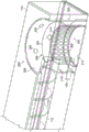
FIG. 3 is a perspective cut-away transparent interior view of the combustion chamber of FIG. 2.
Figure 4 is a side cross-sectional view of another embodiment of a combustion chamber for a particulate grill or other device according to aspects of the present disclosure.
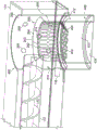
FIG. 5 is a perspective cut-away transparent interior view of the combustion chamber of FIG. 4.
FIG. 6 is a perspective cutaway view of another embodiment of a combustion chamber according to aspects of the present disclosure.
Detailed Description
Referring now to fig. 1, a perspective cross-sectional view of a particulate grill 100 is shown. The particulate grill 100 may be of the type that utilizes particulate fuel, including wood, sawdust, or other components formed into a particulate form for processing and combustion by the grill 100 for cooking or smoking operations. The particulate burning cooking grill 100 provides a firebox or cooking chamber 102 that contains or supports a cooking grate 103. An openable or hinged cover 104 may be provided for selective access to the cooking grate 103. A fuel feed mechanism 110 (shown here as an auger, but which may also be, for example and without limitation, a belt conveyor, a rod/slide conveyor, a push feeder, or other fuel feed mechanism) may transport compressed wood particles or other granular fuel from an external hopper 108 to a typically open-topped cylindrical furnace or combustion chamber 120. The combustion chamber 120 can be supplied with combustion air pressurized and driven by a fan, through ductwork or plenum 114 to the area surrounding the furnace 120, and then through apertures in the exterior of the furnace to feed air into the interior combustion space. In some configurations, the auger 110 operates in an auger tube 112, the auger tube 112 being at least partially located inside the plenum 114.
The electrical resistance igniter 116 may initiate combustion of the fuel inside the combustion chamber 120. Hot gases from the combustion chamber 120 can be delivered through a series of baffles 118 to the cooking grate 103 positioned above the combustion chamber 120.
Referring now to fig. 2, a side cross-sectional view of a combustion chamber 200 for a pellet grill 100 or other device is shown, according to aspects of the present disclosure. In various embodiments, the combustion chamber 200 is an alternative to the combustion chamber 120. In some embodiments, the grill 100 is not further modified because the combustion chamber 200 is a "drop-in" replacement (although it is understood that the combustion chamber 200 may still be inserted, assembled, fixed in place during the original production of the grill 100 or its associated subcomponents, etc.). However, the plenum 114, cooking grate 103, cooking chamber 102, etc. may be sized to take full advantage of the combustion chamber 200. For further explanation, FIG. 3 is a perspective cut-away transparent interior view of the combustion chamber 200 of FIG. 2.
The combustion chamber 200 includes an inner chamber 202, which inner chamber 202 is defined by an inner wall 205 or vessel for combusting fuel particles. The inner wall 205 may be perforated (as shown) or may include other perforated configurations. The perforations 203 may be of various sizes and shapes such that they hold the fuel particles intact while allowing the pressurized combustion gas stream to freely pass to the burning particles inside the inner chamber 202. In some cases the perforations 203 may be very small in order to define a screen. The inner chamber wall 205 may include a heat resistant material (such as a metal alloy) so that it can withstand the long term high temperatures from the burning fuel particles.
In terms of shape, inner chamber 202 may be cylindrical, annular (toroidal), or prismatic, as this is most advantageous for mating with outer chamber 206 (which may be defined by outer wall 209 or a container). Inner chamber 202 and outer chamber 106 may be cylindrical and/or coaxial with respect to one another. A space 207 may be defined between inner chamber 202 and outer chamber 206. The space 207 may be substantially annular such that the distance between the inner chamber 202 and the outer chamber 206 is substantially the same anywhere therebetween.
The outer chamber wall 209 may define an opening or aperture 208, which opening or aperture 208 receives air from the plenum 114 driven or pressurized by the fan 115. The apertures 208 defined by the outer chamber 206 may vary in size and spacing. In one embodiment, the aperture 208 is defined vertically above the inner chamber 202. In some embodiments, another set of apertures 214 is defined through outer chamber wall 209 so as to completely or partially vertically overlap inner chamber 202. Another series of holes 210 may be provided near the igniter 116 to ensure proper ignition operation. Like the aperture 208, the apertures 214 and 210 may be supplied with pressurized air from the plenum 114 driven by the fan 115.
The outer chamber 206 may be cylindrical in form, although other configurations are possible. The size of the inner chamber 202 (either volumetrically or diametrically) can be matched to the size of a single-walled firebox seen in the prior art. The interior chamber 202 can be sized to provide the desired thermal performance of the grill 100 into which the interior chamber 202 is installed. In some embodiments, the outer chamber wall 209 is at least sized larger than prior art hearths to help provide the benefits outlined herein, among others.
In some embodiments, inner chamber 202 and outer chamber 206 share a common floor 212. In some embodiments, outer chamber 206 provides a floor 212 and inner chamber 202 includes walls on floor 212 that are located inside outer chamber 206. An ash opening (also capable of being closed, not shown) may be provided into the combustion chamber 200 via the floor 212. The inner chamber 202 and the outer chamber 206 may have open tops. In some embodiments, inner chamber 202 is shorter than outer chamber 206 so as to fit completely inside outer chamber 206.
The auger 110 and/or auger tube 112 may enter the combustion chamber 200 via an opening through the outer chamber 206 and into the area above the inner chamber 202 such that particles fall from the auger tube 112 into the inner chamber 202. The interior chamber 202 may have a funnel 204 on or near its top to help prevent particles from bouncing or falling out of the interior chamber 202.
Referring now to fig. 4, a side cross-sectional view of another embodiment of a combustion chamber 400 for a pellet grill 100 or other device is shown, in accordance with aspects of the present disclosure. Fig. 5 is a perspective cut-away transparent interior view of the combustion chamber 400. There are some commonalities between the combustion chamber 400 and the combustion chamber 200 discussed above, and components may be understood to be common without further explanation. Both combustors 200,400 (as well as combustor 600 described below) are designed to address a variety of problems associated with prior art hearths and are both upgrades, replacements, or OEM components for solid fuel (e.g., pellet) grills.
The combustion chamber 400 provides an extension 408 chamber of the outer chamber 206 that may extend below the base plate 402 and/or even the plenum 114. Extension chamber 408 may be defined by an outer wall extension 409, which outer wall extension 409 may be integral with outer wall 209 or separately fixed relative to outer wall 209. The inner chamber 202 may also be taller or longer such that it extends all the way to or near the floor 416 of the outer chamber extension 408 while maintaining its upper position relative to the outer chamber 206 and the auger tube 112.
The interior chamber 202 may be divided into two portions by a perforated floor 402. The floor 402 may provide a surface for burning fuel particles while allowing ash to fall into the ash chamber 410 below the floor 402. In this embodiment, the ash chamber 410 may be defined by a portion of the interior chamber wall below the floor 402. The floor 402 may be perforated or have an open portion or screen portion to allow ash and other by-products to fall through. The floor 402 may support unburned or burning solid fuel while allowing ash to fall out so that it does not impede further continued combustion.
The floor 402 may provide an inclined segment 404, the inclined segment 404 being opposite a side where the auger tube 112 is located above the floor 402. This may promote even distribution of the fuel particles as they fall from the auger tube 112. The oblique segment 404 may be provided with an angle of approximately 45 degrees. In other embodiments, the angle may vary (e.g., ranging from about 30 degrees to about 60 degrees). As can be seen in the side cross-sectional view of fig. 4, the sloped segment 404 may occupy less than half of the diameter of the interior 203 while the remainder of the bottom plate 402 remains substantially flat. In some embodiments, the sloped segment 404 comprises approximately 10-20% of the diameter of the inner chamber 202. In one embodiment, the sloped segment 404 comprises approximately 17.6% of the diameter of the internal chamber 202 (as all figures show when viewing the internal profile).
Between the inner chamber 202 and the outer chamber extension 408 (and possibly below the floor 402) is a collector 414. The lip 412 allows ash and debris particles to fall into the collector 414 and away from the side of the internal chamber 202 near the upper portion where combustion occurs. Thereby preventing the accumulation of ash, debris particles, and/or other debris around the internal chamber 202 where an unimpeded flow of gas into the internal chamber 202 is desirable to promote proper combustion of the fuel particles. The collector 414 and the ash collector 410 may be accessible through one or more closable openings (not shown) in the floor 416 or elsewhere.
Referring now to fig. 6, a perspective cutaway view of another embodiment of a combustion chamber 600 is shown, in accordance with aspects of the present disclosure. The combustion chamber 600 shares common components with the combustion chambers 200,400, unless otherwise indicated. The combustion chamber 600 may include an inner chamber 202 defined by an inner wall 205, the inner wall 205 being positioned within an outer chamber 206 defined by an outer wall 209. Inner chamber 202 may be coaxial with outer chamber 206. Outer chamber wall 209 may fit into plenum 114 to receive forced combustion air (positive combustion air) via one or more series of openings 208,210,214 to plenum 114.
The inner wall 205 may be perforated or formed into a screen to allow airflow into the inner chamber 202 where the fuel particles are combusted after being introduced via the auger tube 112. Also in this embodiment, the floor 402 is perforated to allow ash and debris to fall through. An inclined segment 404 of the base plate 402 is also provided. In this embodiment, the inner wall 205 does not extend below the floor 402, but rather, the outer chamber extension 408 is an undivided compartment or ember chamber 410. Extending from a lower portion of the outer wall extension 209 is a bracket 606 that supports a locking nut 604 or other fastener receiving implement. Here, a removable bottom cap or cover 602 may be held against outer wall extension 409 by bolts 608 entering nuts 604. In some embodiments, the bolt 608 is locked to the bottom cover 608 such that the cover 608 may be screwed into the outer wall extension 409.
A support member 610 disposed between the inner wall 205 and the outer wall 209 to support the inner wall 205 in position relative to the outer wall 209 and/or the extension 409. This may be in place of the lip 412 or in addition to the lip 412 (fig. 4-5). Where inner chamber 202 and outer chamber 206 are cylindrical and coaxial, support member 610 may be annular. The support members 610 may be perforated to allow any spilled fuel particles, ash, or other debris that may fall between the locations of the inner wall 205 and the outer wall 209 to pass to the ash chamber 410 (defined herein by the outer wall extension 409). In other embodiments, the funnel portion 204 of the inner chamber wall 205 may extend so as to be close enough to the outer wall 209 or in contact with the outer wall 209 such that the support region 610 does not have to be perforated.
****
It will be understood that the terms "comprises," "comprising," "includes" and "including," and grammatical variants thereof, do not preclude the addition of one or more components, features, steps or integers or groups thereof, and that the terms should be interpreted as specifying the components, features, steps or integers.
If the specification or claims refer to "an additional" element, that does not preclude there being more than one of the additional element.
It should be understood that where the claims or specification refer to "a" or "an" element, such reference is not to be construed as indicating the presence of only one of the element.
It will be understood that where the specification states that a "may," "might," "could," or "may" include an element, feature, structure, or characteristic, that particular element, feature, structure, or characteristic is not required to be included.
Where applicable, although state diagrams, flowcharts, or both may be used to describe embodiments, the inventions are not limited to these diagrams or to the corresponding descriptions. For example, flow need not move through each block or state shown, or in exactly the same order as shown and described.
The methods of the present invention may be implemented by performing or completing manually, automatically, or a combination thereof, selected steps or tasks.
The term "method" may refer to manners, means, techniques and procedures for accomplishing a given task including, but not limited to, those manners, means, techniques and procedures either known to, or readily developed from known manners, means, techniques and procedures by, practitioners of the art to which the invention pertains.
The term "at least" followed by a number is used herein to denote the beginning of a range starting with the number (which may be a range with or without an upper limit, depending on the variable being defined). For example, "at least 1" means 1 or more than 1. The term "at most" is used herein to denote the end of a range ending with a number (which may be a range having 1 or 0 as its lower limit, or a range without a lower limit, depending on the variable being defined). For example, "4 at most" means 4 or less than 4, and "40% at most" means 40% or less than 40%.
In this document, when a range is given as "(first number) to (second number)" or "(first number) - (second number)", this means that the lower limit is the range of the first number and the upper limit is the range of the second number. For example, 25 to 100 should be interpreted to mean a range with a lower limit of 25 and an upper limit of 100. In addition, it should be noted that where a range is given, every possible subrange or interval within the range is also specifically intended unless the context indicates the contrary. For example, if the specification indicates a range of 25 to 100, such range is also intended to include sub-ranges such as 26-100, 27-100, etc., 25-99, 25-98, etc., as well as any other possible combination of lower and higher values within the stated ranges, e.g., 33-47, 60-97, 41-45, 28-96, etc. Note that for illustrative purposes only, integer range values have been used in this paragraph, and fractional values (e.g., 46.7-91.3) should also be understood to be intended as possible subrange endpoints unless specifically excluded.
It should be noted that where reference is made herein to a method comprising two or more defined steps, the defined steps can be performed in any order or simultaneously (unless the context excludes that possibility), and the method can also comprise one or more other steps performed before any defined step, between two defined steps, or after all defined steps (unless the context excludes that possibility).
Further, it should be noted that approximate terms (e.g., "about," "approximately," etc.) should be construed according to ordinary and customary meaning as used in the relevant art, unless otherwise indicated herein. Absent a specific definition within this disclosure, and absent ordinary and customary usage in the relevant art, such terms should be construed as plus or minus 10% of the base value.
Unless otherwise indicated, the use of the terms "selectively" or "selectively" mean that an operation or function can be performed by the referenced structure or device, but that the operation or function may not occur continuously or without interruption. Further, the selective operation or operations selectively performed may be operations that a user or operator of the apparatus or method may select whether or when to perform, but the function or operation may still be fully operational on or within the associated apparatus, machine or method.
*****
The present invention, therefore, is well adapted to carry out the objects and attain the ends and advantages mentioned as well as those inherent therein. While the apparatus of the present invention has been described and illustrated with respect to certain preferred embodiments thereof in connection with the accompanying drawings, many changes and further modifications, in addition to those shown and described herein, may be made therein by those of ordinary skill in the art without departing from the spirit of the inventive concept, which is defined by the following claims.
Claims (20)
1. A combustion chamber, comprising:
an inner wall defining an inner chamber, the inner wall being perforated to allow combustion air to enter the inner chamber;
an outer wall defining an outer chamber, the outer wall perforated to allow combustion air to pass from a pressurized air plenum to the inner wall;
wherein the inner wall and the outer wall are spaced apart such that air can flow between the inner wall and the outer wall; and is
Wherein the inner chamber has an open top to receive solid fuel for combustion in the inner chamber.
2. The combustor of claim 1, further comprising a funnel above the inner chamber, the funnel configured to direct solid fuel into the inner chamber.
3. The combustor of claim 2, wherein said inner chamber and said outer chamber are bounded by a common floor.
4. The combustor of claim 3, wherein said outer wall has perforations at least above and at the same vertical height as said inner wall.
5. The combustor of claim 4, wherein said outer wall has perforations vertically above said funnel.
6. The combustor of claim 1, further comprising a perforated floor in said inner chamber.
7. The combustor of claim 6, further comprising an inclined section of the perforated floor on a side of the inner chamber opposite a location where the solid fuel is introduced.
8. The combustor of claim 7, further comprising an ash chamber below said perforated floor.
9. The combustion chamber of claim 8 further comprising a lower outer chamber extension defined by a lower outer wall extension and containing the ash chamber therein.
10. The combustion chamber of claim 9 further comprising spaced apart regions between the ember chamber and the lower outer chamber extension, the spaced apart regions having inwardly extending lips to collect debris in the spaced apart regions.
11. The combustor of claim 8, further comprising a removable cap at a bottom end of the ember chamber.
12. A cooking grill comprising:
a cooking chamber having a cooking grate supported therein, the cooking grate accessible through an openable cover;
a firebox within the cooking chamber below the cooking grate;
an air plenum that provides pressurized combustion air to the furnace; and
a fan pressurizing air in the plenum;
wherein the furnace further comprises:
an inner wall defining an inner chamber where fuel is combusted; and
an outer chamber wall defining an outer chamber containing the inner chamber;
wherein the outer chamber wall is secured within the plenum and receives pressurized air from the plenum;
wherein the inner wall and the outer wall are spaced apart such that air can flow freely around the inner chamber within the outer chamber; and is
Wherein the inner chamber is perforated to receive combustion air from the outer chamber.
13. The cooking grill of claim 12, further comprising a perforated floor below the inner chamber.
14. The cooking grill of claim 13, further comprising an ash compartment below the perforated floor.
15. The cooking grill of claim 14, further comprising a fuel supply mechanism that traverses the plenum and through the outer chamber wall to deliver fuel into the top of the inner chamber.
16. The cooking grill of claim 15, further comprising a funnel on the inner chamber wall that directs solid fuel from the fuel supply mechanism into the inner chamber.
17. The cooking grill of claim 15, wherein the perforated floor comprises an inclined section and a flat section, the inclined section oriented to direct fuel particles from the fuel supply toward the flat section.
18. A cooking grill comprising:
a cooking chamber having a cooking grate; and
a firebox beneath the cooking grate and at least partially within an air plenum that provides pressurized air to the firebox;
wherein the furnace has an outer chamber defined by perforated outer chamber walls in fluid contact with pressurized air in the plenum; and is
Wherein the furnace has an inner chamber within the outer chamber and defined by a perforated inner chamber wall, the perforations of the inner chamber wall being sized to prevent unburned fuel particles from passing through the perforations of the inner chamber wall, but to allow air flow from the outer chamber through the perforations of the inner chamber wall.
19. The cooking grill of claim 18, further comprising a perforated floor below the inner chamber that allows ash to fall from the inner chamber to an ash chamber at least partially below the plenum.
20. The cooking grill of claim 19, further comprising a fuel supply mechanism through a portion of the plenum and through the outer chamber wall and positioned to provide fuel into a top of the inner chamber.
Applications Claiming Priority (3)
| Application Number | Priority Date | Filing Date | Title |
|---|---|---|---|
| US201962811743P | 2019-02-28 | 2019-02-28 | |
| US62/811743 | 2019-02-28 | ||
| PCT/US2020/020487 WO2020176883A1 (en) | 2019-02-28 | 2020-02-28 | Combustion chamber for pellet grills |
Publications (1)
| Publication Number | Publication Date |
|---|---|
| CN113710128A true CN113710128A (en) | 2021-11-26 |
Family
ID=72239009
Family Applications (1)
| Application Number | Title | Priority Date | Filing Date |
|---|---|---|---|
| CN202080032060.5A Pending CN113710128A (en) | 2019-02-28 | 2020-02-28 | Combustion chamber for particulate grill |
Country Status (6)
| Country | Link |
|---|---|
| US (1) | US20200333011A1 (en) |
| EP (1) | EP3930549A4 (en) |
| CN (1) | CN113710128A (en) |
| AU (1) | AU2020229380A1 (en) |
| CA (1) | CA3131394A1 (en) |
| WO (1) | WO2020176883A1 (en) |
Cited By (1)
| Publication number | Priority date | Publication date | Assignee | Title |
|---|---|---|---|---|
| CN115363061A (en) * | 2022-08-25 | 2022-11-22 | 盐城工学院 | Multilayer granule stove |
Families Citing this family (5)
| Publication number | Priority date | Publication date | Assignee | Title |
|---|---|---|---|---|
| AU2019358216A1 (en) | 2018-10-12 | 2021-06-17 | W.C. Bradley Co. | Pellet grill |
| US11391464B2 (en) * | 2019-02-25 | 2022-07-19 | W.C. Bradley Co. | Enhanced pellet fueled cooking device |
| EP4110063A4 (en) * | 2020-02-28 | 2024-02-28 | Bradley W C Co | Multi-mode cooker with advanced controls |
| USD982373S1 (en) | 2020-04-14 | 2023-04-04 | W.C. Bradley Co. | Mini pellet grill |
| CN111678170A (en) * | 2020-06-16 | 2020-09-18 | 贵州师范大学 | Closed briquette stove for feeding and removing slag of square honeycomb briquet |
Citations (8)
| Publication number | Priority date | Publication date | Assignee | Title |
|---|---|---|---|---|
| US5375540A (en) * | 1993-08-25 | 1994-12-27 | Federal Energy Corporation | System for burning bio-mass and synthetic solid fuel |
| US6223737B1 (en) * | 1999-09-27 | 2001-05-01 | Carrol E. Buckner | Pellet fuel burning device |
| US6336449B1 (en) * | 1997-04-24 | 2002-01-08 | Dell-Point Combustion Inc. | Solid fuel burner for a heating apparatus |
| KR20090119121A (en) * | 2008-05-15 | 2009-11-19 | 김철수 | Brazier apparatus for roast using corns as fuel |
| CN102345861A (en) * | 2010-07-22 | 2012-02-08 | 创意能源控股有限公司 | Combustion apparatus with improved thermal efficiency |
| CN203549790U (en) * | 2013-08-23 | 2014-04-16 | 邓新云 | Biomass burning device |
| US20160341423A1 (en) * | 2015-05-20 | 2016-11-24 | Geoffrey W.A. Johnson | Self Torrefied Pellet Stove |
| US10077904B2 (en) * | 2012-05-08 | 2018-09-18 | Stephen William John Grant | Wood pellet burner assembly |
Family Cites Families (5)
| Publication number | Priority date | Publication date | Assignee | Title |
|---|---|---|---|---|
| US4823684A (en) * | 1987-10-19 | 1989-04-25 | Traeger Joseph P | Pellet-fired barbecue |
| KR100752761B1 (en) * | 2006-12-19 | 2007-08-29 | 김진성 | Burning apparatus using pellet fuel |
| DE102009014010B4 (en) * | 2009-03-19 | 2012-02-23 | Georg Fischer Gmbh & Co. Kg | Burner for solid, lumpy fuel |
| US20110136066A1 (en) * | 2009-12-09 | 2011-06-09 | Geselle James B | Bio-fuel furnace |
| GB201502824D0 (en) * | 2015-02-19 | 2015-04-08 | Standard Brands Uk Ltd | Cooking stove |
-
2020
- 2020-02-28 US US16/805,352 patent/US20200333011A1/en active Pending
- 2020-02-28 CN CN202080032060.5A patent/CN113710128A/en active Pending
- 2020-02-28 AU AU2020229380A patent/AU2020229380A1/en active Pending
- 2020-02-28 EP EP20763840.4A patent/EP3930549A4/en active Pending
- 2020-02-28 WO PCT/US2020/020487 patent/WO2020176883A1/en unknown
- 2020-02-28 CA CA3131394A patent/CA3131394A1/en active Pending
Patent Citations (8)
| Publication number | Priority date | Publication date | Assignee | Title |
|---|---|---|---|---|
| US5375540A (en) * | 1993-08-25 | 1994-12-27 | Federal Energy Corporation | System for burning bio-mass and synthetic solid fuel |
| US6336449B1 (en) * | 1997-04-24 | 2002-01-08 | Dell-Point Combustion Inc. | Solid fuel burner for a heating apparatus |
| US6223737B1 (en) * | 1999-09-27 | 2001-05-01 | Carrol E. Buckner | Pellet fuel burning device |
| KR20090119121A (en) * | 2008-05-15 | 2009-11-19 | 김철수 | Brazier apparatus for roast using corns as fuel |
| CN102345861A (en) * | 2010-07-22 | 2012-02-08 | 创意能源控股有限公司 | Combustion apparatus with improved thermal efficiency |
| US10077904B2 (en) * | 2012-05-08 | 2018-09-18 | Stephen William John Grant | Wood pellet burner assembly |
| CN203549790U (en) * | 2013-08-23 | 2014-04-16 | 邓新云 | Biomass burning device |
| US20160341423A1 (en) * | 2015-05-20 | 2016-11-24 | Geoffrey W.A. Johnson | Self Torrefied Pellet Stove |
Cited By (1)
| Publication number | Priority date | Publication date | Assignee | Title |
|---|---|---|---|---|
| CN115363061A (en) * | 2022-08-25 | 2022-11-22 | 盐城工学院 | Multilayer granule stove |
Also Published As
| Publication number | Publication date |
|---|---|
| EP3930549A1 (en) | 2022-01-05 |
| US20200333011A1 (en) | 2020-10-22 |
| EP3930549A4 (en) | 2022-11-23 |
| WO2020176883A1 (en) | 2020-09-03 |
| AU2020229380A1 (en) | 2021-09-30 |
| CA3131394A1 (en) | 2020-09-03 |
Similar Documents
| Publication | Publication Date | Title |
|---|---|---|
| CN113710128A (en) | Combustion chamber for particulate grill | |
| US11754290B2 (en) | Ash cleanout system | |
| US11092342B2 (en) | Non-gas fire pit | |
| US6223737B1 (en) | Pellet fuel burning device | |
| KR100752761B1 (en) | Burning apparatus using pellet fuel | |
| CN101535721A (en) | Pellet burning heating assembly | |
| KR101291402B1 (en) | Wood pellet stove | |
| US20130174834A1 (en) | Pellet fueled grill with cleanout port | |
| US11730315B2 (en) | Pellet grill | |
| AU637754B2 (en) | Pellet burner appliances and burners therefor | |
| US9995489B2 (en) | Pellet stove | |
| KR101587377B1 (en) | Reverse combustion firewood stove | |
| KR102023110B1 (en) | Stove capable for using both firewood and pellet | |
| KR101909093B1 (en) | Burner assembly for roast | |
| CN219183460U (en) | Granule oven | |
| JP6756963B1 (en) | Pellet combustor and pellet stove | |
| US7900623B2 (en) | Portable freestanding stove | |
| KR101831144B1 (en) | Brazier device for roast | |
| KR101835673B1 (en) | Electronic mat assembly for roast | |
| KR200450221Y1 (en) | brazier apparatus for roast using corns as fuel | |
| AU2022339684A1 (en) | Vertical smoker | |
| JP2022023589A (en) | grill | |
| WO2020183348A1 (en) | Heat generator assembly with a combustion chamber and a brazier | |
| KR20100008591U (en) | brazier apparatus for roast using corns as fuel | |
| BG112531A (en) | Pellet burner, combustion chamber with pellet burner and method for adjusting the power of a pellet fuel combustion chamber |
Legal Events
| Date | Code | Title | Description |
|---|---|---|---|
| PB01 | Publication | ||
| PB01 | Publication | ||
| SE01 | Entry into force of request for substantive examination | ||
| SE01 | Entry into force of request for substantive examination |