Extended-view-field spatial heterodyne interferometer optical system for Raman spectrum detection
Technical Field
The invention relates to a spectrum detection technology, in particular to a field-expanding spatial heterodyne interferometer optical system for Raman spectrum detection.
Background
The Raman spectrum technology is a spectrum inspection technology based on a Raman effect, utilizes laser to irradiate a sample to be detected, collects and analyzes Raman scattered light generated by the sample, realizes qualitative analysis and theoretic measurement on the sample, and has the characteristics of accuracy, no damage, high efficiency, obvious characteristic peak, good reproducibility, no need of sample preparation and the like.
Currently, a commonly used raman spectrometer mostly adopts a grating spectrometer without a moving part. Such spectrometers require a small slit to achieve high spectral resolution, and such small slit designs will limit the amount of light that passes into the spectrometer, limit the detection sensitivity of the system, and limit the spectral range of the system.
Disclosure of Invention
The invention provides a spread-field spatial heterodyne interferometer optical system for Raman spectrum detection, which aims to solve the technical problems that an existing Raman spectrometer needs a small slit to obtain high spectral resolution, and the design of the small slit limits the light flux entering the spectrometer, the detection sensitivity of the system and the spectral range.
In order to achieve the purpose, the technical scheme provided by the invention is as follows:
a spread-field spatial heterodyne interferometer optical system for Raman spectrum detection is characterized in that: the system comprises a front collimating lens, a spatial heterodyne interferometer, a fringe imaging lens and a photoelectric detector which are sequentially arranged along a light path;
the front collimating lens is used for transmitting incident exciting light to the spatial heterodyne interferometer in a parallel light mode;
the spatial heterodyne interferometer is used for forming an interference pattern on a localized surface by incident parallel light and comprises an optical filter, a beam splitter, a first field broadening prism, a second field broadening prism, a first grating and a second grating;
the optical filter and the beam splitter are sequentially arranged on an emergent light path of the front collimating lens;
the first grating is parallel to the rear surface of the first field widening prism, and the first grating and the rear surface of the first field widening prism form a first optical unit;
the second grating is parallel to the rear surface of the second field widening prism, and the second grating and the rear surface of the second field widening prism form a second optical unit; the first optical unit and the second optical unit are respectively positioned in the two outgoing light paths of the beam splitter;
the fringe imaging lens is used for imaging the formed interference pattern on the photoelectric detector.
Further, the wavelength of the excitation light is 532 nm;
the first field widening prism and the second field widening prism are the same prisms, and the vertex angle is 3.02 degrees;
the groove density of the first grating and the groove density of the second grating are both 150gr/mm, and the blaze angle is 2.33 degrees.
Furthermore, the fringe imaging lens is of a full-symmetrical structure and comprises a first lens group unit, an aperture diaphragm and a second lens group unit which are coaxially arranged along a light path in sequence;
the first lens group unit comprises a first imaging lens, a second imaging lens and a cemented lens group which are coaxially arranged along a light path in sequence, the first imaging lens is a double convex positive lens, and the second imaging lens is a meniscus positive lens which is convex towards an object space;
the bonding lens group is formed by bonding a third imaging lens and a fourth imaging lens, the third imaging lens is a biconvex positive lens, and the fourth imaging lens is a biconcave negative lens; the second lens group unit and the first lens group unit have the same structure and are in mirror symmetry with respect to the aperture diaphragm.
Further, the light passing diameter of the front collimating lens at the optical filter is 26mm +/-0.1 mm;
the distance between the optical filter and the beam splitter is 15mm +/-0.1 mm;
the distance between the stripe imaging lens and the beam splitter is 12mm +/-0.04 mm;
the distance between the stripe imaging lens and the photoelectric detector is 46.4mm +/-0.04 mm;
the interval between the first imaging lens and the second imaging lens is 41.9mm +/-0.04 mm;
the interval between the second imaging lens and the third imaging lens is 0.7mm +/-0.04 mm;
the distance between the fourth imaging lens and the aperture diaphragm is 9.2mm +/-0.02 mm.
Further, the center wavelength of the optical filter is 610.5nm, and the full width at half maximum of the peak value is 131 nm.
Further, the materials of the first imaging lens, the second imaging lens, the third imaging lens and the fourth imaging lens are H-ZK21, H-ZK21, H-ZK3 and H-F4 respectively.
Further, a light incident surface of the lens is defined as a front surface, and a light emergent surface of the lens is defined as a rear surface;
the thickness of the first imaging lens is 5mm, the front surface of the first imaging lens is a spherical surface, the curvature radius is 132.07mm, the rear surface of the first imaging lens is a spherical surface, and the curvature radius is-88.51 mm;
the thickness of the second imaging lens is 5mm, the front surface of the second imaging lens is a spherical surface, the curvature radius of the second imaging lens is 37.4mm, the rear surface of the second imaging lens is a spherical surface, and the curvature radius of the second imaging lens is 134.94 mm;
the thickness of the third imaging lens is 7mm, the front surface of the third imaging lens is a spherical surface, the curvature radius is 18.33mm, and the curvature radius of the rear surface is-53.12 mm;
the thickness of the fourth imaging lens is 6mm, the front surface of the fourth imaging lens is a spherical surface, the curvature radius of the fourth imaging lens is-53.12 mm, the rear surface of the fourth imaging lens is a spherical surface, and the curvature radius of the fourth imaging lens is 11.368 mm.
Further, the stripe imaging lens has the working F/# of 12, the magnification of-1X, the image height of 10mm X16 mm and the telecentricity of less than 0.1 degrees.
Furthermore, the optical filter is a broadband pass optical filter, the high-transmittance wavelength is 545 nm-676 nm, and the suppression waveband is 300 nm-1200 nm.
Furthermore, the photoelectric detector is an sCOMS detector, the spectral response range is 400 nm-800 nm, the detector resolution is 1125 multiplied by 1875, and the pixel size is 8 μm.
Or, the photoelectric detector is a CCD camera, the spectral range is visible light, the pixel size is 8 μm, the resolution is 1125 multiplied by 1875, and the working temperature is-40 ℃ to +71 ℃.
Compared with the prior art, the invention has the advantages that:
1. according to the invention, by applying the spatial heterodyne interferometer to Raman spectrum detection, the Raman spectrum of a 532nm excitation light source can be detected, and the accuracy requirement of Raman spectrum inversion is met.
2. According to the invention, through the design of the spatial heterodyne interferometer and the fringe imaging lens, the optical path difference is introduced by adopting a spatial heterodyne method, the high spectral resolution is realized on the premise of not introducing a motion module, the field broadening prism and the grating of the spatial heterodyne interferometer are designed, the interference fringe modulation degree corresponding to the off-axis field light is effectively improved, the field angle of system work is increased, the application of the field broadening spatial heterodyne interferometer in a Raman spectrum detector is realized, the simulated interference fringe obtained by the interferometer system in the working waveband has higher modulation degree, the accuracy requirement of Raman spectrum inversion with the excitation wavelength of 532nm can be met, and the spectral resolution reaches 4cm-1。
3. Compared with the existing spectrometer, the invention has no limitation of the slit, thus having higher luminous flux and wider spectral range; compared with the existing Michelson Raman spectrometer, the invention has no moving part, and has higher stability, smaller volume and higher time resolution.
Drawings
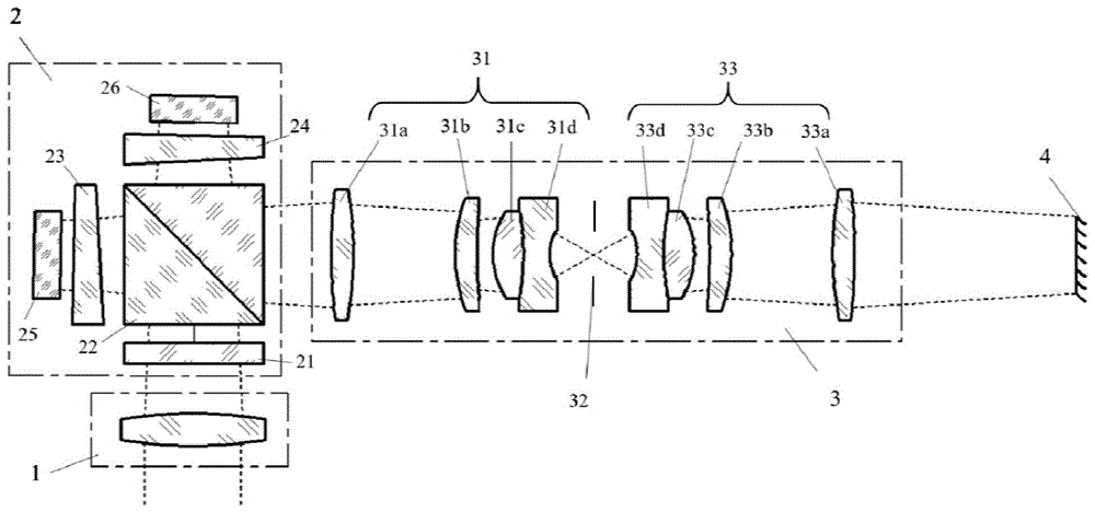
FIG. 1 is a schematic diagram of an optical path structure of an extended field of view spatial heterodyne interferometer optical system for Raman spectrum detection according to the present invention;
FIG. 2 is a schematic diagram of a fringe imaging lens in an optical system of the extended-field spatial heterodyne interferometer for Raman spectrum detection according to the present invention;
FIG. 3 is a point array diagram of a fringe imaging lens in an optical system of the extended field-of-view spatial heterodyne interferometer for Raman spectrum detection under different fields of view according to the present invention;
FIG. 4 is a graph of MTF of a fringe imaging lens in an optical system of the extended field-of-view spatial heterodyne interferometer for Raman spectrum detection according to the present invention;
FIG. 5 is a simulated interferogram of 545nm monochromatic light incident on the extended field spatial heterodyne interferometer optical system for Raman spectroscopy of the present invention;
FIG. 6 is a simulated interferogram of a spread-field spatial heterodyne interferometer optical system for Raman spectroscopy of the present invention with polychromatic light incident thereon;
FIG. 7 is a simulated spectrum of polychromatic light incident on the extended field-of-view spatial heterodyne interferometer optical system for Raman spectroscopy of the present invention;
wherein the reference numbers are as follows:
1-front collimating lens;
2-a spatial heterodyne interferometer, 21-a filter, 22-a beam splitter, 23-a first field broadening prism, 24-a second field broadening prism, 25-a first grating and 26-a second grating;
3-stripe imaging lens, 31-first lens group unit, 31 a-first imaging lens, 31 b-second imaging lens, 31 c-third imaging lens and 31 d-fourth imaging lens; 32-aperture diaphragm, 33-second lens group unit, 33 a-fifth imaging lens, 33 b-sixth imaging lens, 33 c-seventh imaging lens and 33 d-eighth imaging lens;
4-photo detector.
Detailed Description
To make the objects, advantages and features of the present invention more apparent, the optical system of extended-field spatial-heterodyne interferometer for raman spectroscopy proposed by the present invention is further described in detail with reference to the accompanying drawings and specific embodiments.
The embodiment provides an optical system of a field-expanding spatial heterodyne raman interferometer, which is used for detecting a raman spectrum signal of a 532nm excitation light source, and as shown in fig. 1, the optical system comprises a front collimating lens 1, a spatial heterodyne interferometer 2, a fringe imaging lens 3 and a photoelectric detector 4; the wavefront of a target to be detected is collimated by a front collimating lens 1 and transmitted to a spatial heterodyne interferometer 2, incident parallel light generates a series of interference patterns at a localized surface by the spatial heterodyne interferometer 2, the interference patterns are imaged on a target surface of a photoelectric detector 4 in proportion by a fringe imaging lens 3, and the interference patterns are recorded by the photoelectric detector 4; and finally, obtaining the Raman spectrum information of the target to be detected through data inversion.
The front collimating lens 1 only needs to meet the requirement of limiting the clear aperture of the corresponding position in the light path and the incidence of parallel light.
The spatial heterodyne interferometer 2 includes an optical filter 21, a beam splitter 22, a first field widening prism 23, a first grating 25, a second field widening prism 24, and a second grating 26; the beam splitter 22 is placed in the emergent light path of the front collimating lens 1, the optical filter 21 is placed between the beam splitter 22 and the front collimating lens 1, the first grating 25 is parallel to the rear surface of the first field widening prism 23, the first grating and the first field widening prism form a first optical unit, the second grating 26 is parallel to the rear surface of the second field widening prism 24, the second grating and the second grating form a second optical unit, and the first optical unit and the second optical unit are respectively located in the two emergent light paths of the beam splitter 22.
The filter 21 is a broadband pass filter, the high transmission wavelength is 545 nm-676 nm, and the inhibition waveband is 300 nm-1200 nm. The center wavelength of the optical filter 21 of the present embodiment is 610.5nm, and the peak full width at half maximum is 131 nm; the first field widening prism 23 and the second field widening prism 24 are the same prisms, and the vertex angle is 3.02 degrees; the groove density of the first grating 25 and the second grating 26 is 150gr/mm (line pair/mm) and the blaze angle is 2.33 °.
The light transmission diameter of the front collimating lens 1 at the position of the optical filter 21 is 26mm +/-0.1 mm; the distance between the optical filter 21 and the beam splitter 22 of the spatial heterodyne interferometer 2 is 15mm +/-0.1 mm; the distance between the beam splitter 22 of the spatial heterodyne interferometer 2 and the fringe imaging lens 3 is 12mm +/-0.04 mm.
As shown in fig. 2, the fringe imaging lens 3 has an operation F/# of 12, a magnification of-1 ×, an image height of 10mm × 16mm, and a telecentricity of less than 0.1 °. The fringe imaging lens 3 has a fully symmetric structure, and includes a first lens group unit 31, an aperture stop 32, and a second lens group unit 33, which are coaxially arranged in sequence along a light path.
The first lens group unit 31 includes a first imaging lens 31a, a second imaging lens 31b, a third imaging lens 31c and a fourth imaging lens 31d coaxially arranged in this order along the optical path; wherein the third imaging lens 31c and the fourth imaging lens 31d form a cemented lens group; the first imaging lens 31a is a biconvex positive lens, the second imaging lens 31b is a meniscus positive lens convex toward the object, the third imaging lens 31c is a biconvex positive lens, and the fourth imaging lens 31d is a biconcave negative lens;
the second lens group unit 33 and the first lens group unit 31 have the same structure, and are mirror-symmetrical with respect to the aperture stop 32, specifically, the second lens group unit 33 includes a fifth imaging lens 33a, a sixth imaging lens 33b, a seventh imaging lens 33c and an eighth imaging lens 33d coaxially arranged along the optical path in sequence, the fifth imaging lens 33a and the fourth imaging lens 31d have the same surface-type structure, and are mirror-symmetrical with respect to the aperture stop 32, the sixth imaging lens 33b and the third imaging lens 31c have the same surface-type structure, and are mirror-symmetrical with respect to the aperture stop 32, the seventh imaging lens 33c and the second imaging lens 31b have the same surface-type structure, and are mirror-symmetrical with respect to the aperture stop 32, and the eighth imaging lens 33d and the first imaging lens 31a have the same surface-type structure, and are mirror-symmetrical with respect to the aperture stop 32.
The distance between the stripe imaging lens 3 and the photoelectric detector 4 is 46.4mm +/-0.04 mm; the distance from the first imaging lens 31a to the second imaging lens 31b in the streak imaging lens 3 is 41.9mm ± 0.04mm, the distance from the second imaging lens 31b to the third imaging lens 31c is 0.7mm ± 0.04mm, and the distance from the fourth imaging lens 31d to the aperture stop 32 is 9.2mm ± 0.02 mm. The second lens group unit 33 and the first lens group unit 31 have the same structure, and the distance from the aperture stop 32 to the fifth imaging lens 33a is 9.2mm ± 0.02 mm; the distance from the sixth imaging lens 33b to the seventh imaging lens 33c is 0.7mm ± 0.04 mm; the distance from the seventh imaging lens 33c to the eighth imaging lens 33d is 41.9mm ± 0.04 mm.
The specific structural parameters of the partial lens in the optical system of this embodiment are as follows (in mm):
the streak imaging lens 3 has a fully symmetric structure, and the fifth, sixth, seventh and eighth imaging lenses 33a, 33b, 33c and 33d of the second lens group unit 33 are made of the same material as the fourth, third and first imaging lenses 31d, 31c, 31b and 31a, respectively, i.e. the fifth, sixth, seventh and eighth imaging lenses 33a, 33b, 33c and 33d are made of H-F4, H-ZK3, H-ZK21 and H-ZK21, respectively;
the curvature radii of the fifth imaging lens 33a, the sixth imaging lens 33b, the seventh imaging lens 33c and the eighth imaging lens 33d are respectively matched with the curvature radii of the fourth imaging lens 31d, the third imaging lens 31c, the second imaging lens 31b and the first imaging lens 31a, namely the thickness of the fifth imaging lens 33a is 6mm, the front surface of the fifth imaging lens is a spherical surface, the curvature radius is-11.368 mm, the rear surface of the fifth imaging lens is a spherical surface, and the curvature radius is 53.12 mm; the thickness of the sixth imaging lens 33b is 7mm, the front surface thereof is a spherical surface, the radius of curvature is 53.12mm, and the radius of curvature of the rear surface is-18.33 mm; the thickness of the seventh imaging lens 33c is 5mm, the front surface thereof is a spherical surface with a curvature radius of-134.94 mm, the rear surface thereof is a spherical surface with a curvature radius of-37.4 mm; the eighth imaging lens 33d has a thickness of 5mm, a spherical front surface with a radius of curvature of 88.51mm, and a spherical rear surface with a radius of curvature of-132.07 mm.
The lenses of the fringe imaging lens 3 of the embodiment are spherical surfaces, are easy to process and manufacture, and have low cost.
The photoelectric detector 4 of the embodiment is an SCOMS detector, the spectral response range is 400 nm-800 nm, the detector resolution is 1125 multiplied by 1875, and the pixel size is 8 μm. In other embodiments, the photodetector 4 can also be a CCD camera with a spectrum range of visible light, a pixel size of 8 μm, a resolution of 1125 × 1875, and an operating temperature of-40 ℃ to +71 ℃.
Referring to fig. 3 and 4, the dot-column diagram of the fringe imaging lens 3 under normal temperature and pressure in this embodiment reflects the size of the imaging dispersed spot of the optical system on the image plane, and it can be seen that the RMS radii of the on-axis field and the off-axis field both meet the design requirements; at the Nyquist frequency of 65p/mm, the MTF curve of the optical system of the embodiment is close to the diffraction limit, and the requirement of image quality is met.
Referring to fig. 5, the interference fringes corresponding to the 540nm wavelength at normal temperature and normal pressure are obtained by full-system simulation of the extended-field spatial heterodyne raman interferometer of the present embodiment, and it can be seen from the interference fringes, the modulation degrees of which are all above 0.99, and the quality of the obtained interference image is good.
Referring to fig. 6 and 7, in the embodiment, the interference fringes corresponding to the polychromatic light and the spectrogram obtained by inversion are obtained by full-system simulation of the extended-field spatial heterodyne interferometer, and the spectral resolution is 4cm-1The spectral resolution meets the requirements.
In summary, in the embodiment, by means of the optical design of the front collimating lens 1, the spatial heterodyne interferometer 2, and the fringe imaging lens 3, the optical overall system setup of the spatial heterodyne raman interferometer is realized, the modulation degree of interference fringes obtained through simulation under the working condition can meet the precision requirement of data inversion, and a computational simulation model is provided for the inversion of the subsequent raman spectrum.
The embodiment realizes the application of the spatial heterodyne interferometer in the aspect of Raman spectrum detection, and through the design of the spatial heterodyne interferometer 2 and the fringe imaging lens 3, the simulated interference fringes obtained by the interference system in the working waveband have higher modulation degree, and can detect the Raman spectrum of a 532nm excitation light source, thereby meeting the accuracy requirement of Raman spectrum inversion.
In the embodiment, the field widening prism is added in the spatial heterodyne interferometer, so that the interference fringe modulation degree corresponding to the off-axis field light is effectively improved, and the working field angle of the system is increased.
The above description is only for the preferred embodiment of the present invention and does not limit the technical solution of the present invention, and any modifications made by those skilled in the art based on the main technical idea of the present invention belong to the technical scope of the present invention.