Container carrying system and carrying method
Technical Field
The invention relates to the technical field of container handling, in particular to the technical field of container handling systems and container handling methods.
Background
The existing container is usually loaded by using a flat tractor or hoisted by a crane in the transportation process, the defects of high cost and large occupied area exist in both flat traction loading and crane hoisting, the defects of time and labor waste and high cost exist in loading and unloading the container on the flat car, and the defects of low stability, inconvenient lifting, inconvenient steering and high transportation cost exist in the existing crane and flat tractor.
Therefore, the transfer system which is small in size, strong in flexibility and convenient to lift is designed to have practical significance.
Disclosure of Invention
The invention aims to: in order to solve the above technical problems, the present invention provides a container handling system and a container handling method.
The invention specifically adopts the following technical scheme for realizing the purpose:
the utility model provides a container handling system, includes the container and can dismantle four compound floor truck that set up can drive the container in container four corners department and remove and go up and down, all be provided with the controller that control self goes up and down and remove on four compound floor truck, four controller electricity each other are connected, and one of them controller is main control unit, and main control unit makes the container realize synchronous lift through other three controllers, is provided with the connecting piece between two compound floor truck that are located arbitrary one end of container, is connected with the tractor through the subassembly that drags on the connecting piece.
The composite carrying trolley comprises a walking mechanism at the bottom, a rotating mechanism arranged on the walking mechanism, a lifting column assembly arranged on the rotating mechanism, an installation sleeve sleeved on the lifting column assembly and a connecting seat fixedly arranged on the installation sleeve and detachably connected with a container, wherein a generator for increasing the cruising ability is arranged on the walking mechanism, and a controller electrically connected with the walking mechanism, the rotating mechanism, the lifting column assembly and the generator is also arranged on the walking mechanism.
Preferably, controller and direct current variable frequency generator range upon range of setting, and still be provided with the control panel of the manual operation of being convenient for on the controller, the last folding plate that is close to control panel department and still is provided with the operating personnel of being convenient for and stand and be convenient for accomodate of running gear.
Preferably, the lifting column assembly comprises a mounting seat fixedly arranged above the rotating mechanism, an electric cylinder or a hydraulic cylinder arranged on the mounting seat, and a lifting outer sleeve which is sleeved outside the electric cylinder or the hydraulic cylinder and can be sealed along the top of the electric cylinder or the hydraulic cylinder, wherein the mounting sleeve is fixedly arranged on the lifting outer sleeve.
More preferably, running gear is tricycle running gear, and running gear includes the vehicle bottom board and sets up at the driving wheel subassembly of vehicle bottom board and follow driving wheel subassembly, from the universal wheel subassembly that highly can adjust, driving wheel subassembly includes that the symmetry sets up in vehicle bottom board both sides and the independent control's driving wheel A and driving wheel B.
A method of container handling comprising the steps of:
step 1, detachably mounting four composite carrying trolleys on preformed holes at four corners of a container;
step 2, retracting the driven wheel assemblies of the four composite carrying trolleys to enable the container and the four composite carrying trolleys to form a stable movable container box assembly;
step 3, electrically connecting controllers of the four composite carrying trolleys, wherein one controller is a main controller, controlling other three controllers to realize synchronous lifting of the container by the main controller, and lifting the container to a proper height to stop lifting;
step 4, connecting the two composite carrying trolleys at one end of the container through a connecting piece, and connecting the two composite carrying trolleys with a traction vehicle head through a traction assembly to form a traction whole;
and 5, the traction vehicle head carries the container through the traction assembly.
The invention has the following beneficial effects:
1. the container carrying method has the advantages of small occupied area, strong flexibility, high transferring efficiency and convenience in adjusting the height of the container.
2. The composite carrying trolley is reasonable in design, mainly comprises a travelling mechanism, a rotating mechanism, a lifting mechanism, a mounting seat, a generator and a controller, has the advantages of small occupied area, strong stability, convenience in driving the mounting seat to rotate and lift, high automation degree, capability of increasing the endurance of the trolley due to the arrangement of the generator, and high automation degree, and can be used for controlling the controller on the container trolley manually through a remote controller or remotely controlling the controller at a PC (personal computer) end.
3. Due to the blocking of the controller and other parts of the trolley, the rotating mechanism can rotate by plus or minus 60 degrees in the vertical direction, and the rotating angle of the rotating mechanism can reach 120 degrees, namely the rotating mechanism drives the mounting seat to rotate within 120 degrees; after the mounting seat of the trolley is connected with the container, when the rotating mechanism rotates, the mounting seat connected with the container cannot rotate due to the fact that the container is too heavy, the rotating mechanism drives the trolley body of the trolley to rotate, and after the trolley body rotates to a required position, the trolley body stops rotating, so that the container can move transversely, longitudinally and longitudinally through rotation of the trolley body by 90 degrees, and the trolley has high flexibility.
4. The driving wheel assembly consists of a driving wheel A and a driving wheel B which are controlled independently, so that when the trolley needs to run straight, the rotating speeds of the driving wheel A and the driving wheel B are controlled to be consistent, and the trolley can run straight; when the trolley needs to turn or turn around, the rotating speed difference exists between the rotating speeds of the driving wheel A and the driving wheel B, and the trolley has stronger flexibility due to the arrangement of independent control.
5. The driven wheel component is a universal wheel component with adjustable height, the arrangement of the driven wheel with the structure enables the trolley to be suitable for different working conditions, and when the trolley is used independently, the bottom parts of the driven wheel component and the driving wheel component are flush to form a three-wheel travelling mechanism; when the dolly and the container cooperation use, when four dollies can be dismantled with the container and be connected promptly, the driven wheel subassembly of every dolly all upwards is packed up, does not contact with ground, makes it become two-wheeled running gear, increases the flexibility that the container was transported.
Drawings
FIG. 1 is a schematic view of the present invention;
FIG. 2 is a schematic view of the construction of the carrier;
FIG. 3 is a schematic view of the structure of FIG. 2 from another perspective;
FIG. 4 is a view in elevation of FIG. 2;
FIG. 5 is a top view of FIG. 4;
FIG. 6 is a left side view of FIG. 4;
FIG. 7 is a cross-sectional view taken at the line A-A in FIG. 4
FIG. 8 is a cross-sectional view taken at FIG. 5B-B;
FIG. 9 is a cross-sectional view at FIG. 5C-C;
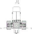
FIG. 10 is a cross-sectional view taken at D-D of FIG. 4;
FIG. 11 is a cross-sectional view taken at E-E of FIG. 4;
FIG. 12 is a schematic view of the structure of the mounting sleeve and the connecting socket;
FIG. 13 is a schematic view of a portion of the structure of FIG. 1;
reference numerals: the device comprises a lifting column assembly 1, a lifting column assembly 1-1, a mounting seat 1-2, an electric cylinder 1-3, a lifting outer sleeve 1-3, a connecting seat 2-2, a triangular reinforcing block 2-1, a mounting plate 2-2, a bolt assembly 2-3, a mounting sleeve 3-3, a U-shaped groove 3-1, a rotating mechanism 4, a driving wheel A5, a driven wheel assembly 6, a folding plate 7, a controller 8 and a driving wheel B9.
Detailed Description
In order to make the objects, technical solutions and advantages of the embodiments of the present invention clearer, the technical solutions in the embodiments of the present invention will be clearly and completely described below with reference to the drawings in the embodiments of the present invention, and it is obvious that the described embodiments are some, but not all, embodiments of the present invention. The components of embodiments of the present invention generally described and illustrated in the figures herein may be arranged and designed in a wide variety of different configurations.
Thus, the following detailed description of the embodiments of the present invention, presented in the figures, is not intended to limit the scope of the invention, as claimed, but is merely representative of selected embodiments of the invention. All other embodiments, which can be derived by a person skilled in the art from the embodiments given herein without making any creative effort, shall fall within the protection scope of the present invention.
It should be noted that: like reference numbers and letters refer to like items in the following figures, and thus, once an item is defined in one figure, it need not be further defined and explained in subsequent figures. Furthermore, the terms "first," "second," and the like are used merely to distinguish one description from another, and are not to be construed as indicating or implying relative importance.
In the description of the embodiments of the present invention, it should be noted that the terms "inside", "outside", "upper", and the like indicate orientations or positional relationships based on the orientations or positional relationships shown in the drawings or orientations or positional relationships conventionally arranged when products of the present invention are used, and are only used for convenience in describing the present invention and simplifying the description, but do not indicate or imply that the devices or elements indicated must have specific orientations, be constructed in specific orientations, and operated, and thus, cannot be construed as limiting the present invention.
Example 1
As shown in fig. 1 to 12, this embodiment provides a container handling system, including the container with can dismantle four composite floor truck that set up can drive the container and remove and go up and down in container four corners department, all be provided with the controller that control self goes up and down and remove on four composite floor truck, four controller electricity each other are connected, one of them controller is main control unit, main control unit makes the container realize synchronous lift through other three controllers, is provided with the connecting piece between two composite floor truck that are located the arbitrary one end of container, is connected with the tractor through pulling the subassembly on the connecting piece.
The composite carrying trolley comprises a walking mechanism at the bottom, a rotating mechanism 4 arranged on the walking mechanism, a lifting column assembly 1 arranged on the rotating mechanism 4, an installation sleeve 3 sleeved on the lifting column assembly 1, and a connecting seat 2 fixedly arranged on the installation sleeve 3 and detachably connected with a container, wherein a generator for increasing the cruising ability is arranged on the walking mechanism, and a controller 8 electrically connected with the walking mechanism, the rotating mechanism 4, the lifting column assembly 1 and the generator is also arranged on the walking mechanism.
The generator is a direct current variable frequency generator.
Controller 8 and the range upon range of setting of direct current variable frequency generator, and still be provided with the control panel of the manual operation of being convenient for on the controller 8, the last folding plate 7 that is close to control panel department and still is provided with the operating personnel of being convenient for and is convenient for to accomodate that stands of running gear.
The rotating mechanism 4 is a rotating platform, and the rotating angle of the rotating platform is-60 degrees.
Due to the blocking of the controller and other parts of the trolley, the rotating mechanism can rotate by plus or minus 60 degrees in the vertical direction, and the rotating angle of the rotating mechanism can reach 120 degrees, namely the rotating mechanism drives the mounting seat to rotate within 120 degrees; after the mounting seat of the trolley is connected with the container, when the rotating mechanism rotates, the mounting seat connected with the container cannot rotate due to the fact that the container is too heavy, the rotating mechanism drives the trolley body of the trolley to rotate, the trolley body rotates to a required position and then stops rotating, the trolley body rotates 90 degrees to realize the transverse and longitudinal movement of the container, and the trolley has high flexibility.
The controller is controlled manually by a remote controller or remotely by a PC terminal.
The transport dolly of this embodiment design mainly comprises running gear, slewing mechanism, elevating system, mount pad, generator and controller, has that area is little, stable to strong, conveniently drives the mount pad and rotates and go up and down, degree of automation is high, the setting of generator can increase the advantage of dolly continuation of the journey, it is high to be automatic to become all can pass through the controller on the artifical vehicle-mounted control of remote controller or the PC end remote control container dolly.
When the container is transferred, four trolleys are needed to clamp four edges of the container, so that the container can be moved and lifted in the middle, the traditional trailer or crane occupies large space and is not suitable for wharfs or other collecting and distributing places with limited space, and the trolley designed by the invention is small in size and is suitable for transferring the container with limited space.
The lifting column assembly 1 comprises a mounting seat 1-1 fixedly arranged above the rotating mechanism, an electric cylinder 1-2 or a hydraulic cylinder arranged on the mounting seat 1-1, and a lifting outer sleeve 1-3 sleeved on the electric cylinder 1-2 or the hydraulic cylinder and capable of lifting along the electric cylinder 1-2 or the hydraulic cylinder, wherein the top of the lifting outer sleeve is sealed, and the mounting sleeve 3 is fixedly arranged on the lifting outer sleeve 1-3.
The lifting outer sleeve 1-3 is a square column in appearance, the mounting sleeve 3 is a square block, and a U-shaped groove 3-1 matched with the square column in shape is formed in one side of the mounting sleeve 3.
The connecting seat 2 comprises a mounting plate 2-2 vertically arranged on the outer side of the mounting sleeve 3, the mounting sleeve 3 extends from the upper end and the lower end of the mounting plate 2-2, bolt assemblies 2-3 detachably connected with the container are arranged at the two ends of the mounting plate 2-2 extending out of the mounting sleeve 3, and triangular reinforcing blocks 2-1 connected with the mounting plate 2-2 are arranged at the upper end and the lower end of the mounting sleeve 3.
Running gear is tricycle running gear, and running gear includes the vehicle bottom board and sets up at the driving wheel subassembly of vehicle bottom board and follows driving wheel subassembly 6, follow driving wheel subassembly 6 and be the universal wheel subassembly that highly can adjust, driving wheel subassembly includes that the symmetry sets up in vehicle bottom board both sides and independent control's driving wheel A5 and driving wheel B9.
The driving wheel assembly is located on the side of the lifting column assembly 1, and the driven wheel assembly 6 is located on the side of the controller 8.
The universal wheel assembly comprises a telescopic mechanism connected with the vehicle bottom plate and universal wheels arranged at the bottom of the telescopic mechanism.
The telescopic mechanism is one of an electric cylinder, a lifting sleeve or an air cylinder.
In the embodiment, the driving wheel assembly consists of the driving wheel A and the driving wheel B which are controlled independently, so that when the trolley needs to run straight, the rotation speeds of the driving wheel A and the driving wheel B are controlled to be consistent, and the trolley runs straight; when the trolley needs to turn or turn around, the rotating speed difference exists between the rotating speeds of the driving wheel A and the driving wheel B, and the trolley has stronger flexibility due to the arrangement of independent control.
The driven wheel component is a universal wheel component with adjustable height, the arrangement of the driven wheel with the structure enables the trolley to be suitable for different working conditions, and when the trolley is used independently, the bottom parts of the driven wheel component and the driving wheel component are flush to form a three-wheel travelling mechanism; when the dolly and the container cooperation use, when four dollies can be dismantled with the container and be connected promptly, the driven wheel subassembly of every dolly all upwards is packed up, does not contact with ground, makes it become two-wheeled running gear, increases the flexibility that the container was transported.
Example 2
A method of container handling comprising the steps of:
step 1, detachably mounting four composite carrying trolleys on preformed holes at four corners of a container;
step 2, retracting the driven wheel assemblies of the four composite carrying trolleys to enable the container and the four composite carrying trolleys to form a stable movable container box assembly;
step 3, electrically connecting controllers of the four composite carrying trolleys, wherein one controller is a main controller, controlling other three controllers to realize synchronous lifting of the container by the main controller, and lifting the container to a proper height to stop lifting;
step 4, connecting the two composite carrying trolleys at one end of the container through a connecting piece, and connecting the two composite carrying trolleys with a traction vehicle head through a traction assembly to form a traction whole;
and 5, the traction vehicle head carries the container through the traction assembly.