CN113577459A - Drug delivery device - Google Patents
Drug delivery device Download PDFInfo
- Publication number
- CN113577459A CN113577459A CN202111017968.1A CN202111017968A CN113577459A CN 113577459 A CN113577459 A CN 113577459A CN 202111017968 A CN202111017968 A CN 202111017968A CN 113577459 A CN113577459 A CN 113577459A
- Authority
- CN
- China
- Prior art keywords
- housing
- needle
- drug
- assembly
- power unit
- Prior art date
- Legal status (The legal status is an assumption and is not a legal conclusion. Google has not performed a legal analysis and makes no representation as to the accuracy of the status listed.)
- Pending
Links
- 238000012377 drug delivery Methods 0.000 title claims abstract description 66
- 239000003814 drug Substances 0.000 claims abstract description 317
- 229940079593 drug Drugs 0.000 claims abstract description 144
- 238000003780 insertion Methods 0.000 claims abstract description 99
- 230000037431 insertion Effects 0.000 claims abstract description 99
- 230000007246 mechanism Effects 0.000 claims abstract description 69
- 238000000034 method Methods 0.000 claims abstract description 12
- 229940090047 auto-injector Drugs 0.000 claims description 54
- 239000007924 injection Substances 0.000 claims description 35
- 238000002347 injection Methods 0.000 claims description 35
- 238000007789 sealing Methods 0.000 claims description 24
- 230000008878 coupling Effects 0.000 claims description 20
- 238000010168 coupling process Methods 0.000 claims description 20
- 238000005859 coupling reaction Methods 0.000 claims description 20
- 239000000463 material Substances 0.000 claims description 12
- 230000000717 retained effect Effects 0.000 claims description 9
- 238000004519 manufacturing process Methods 0.000 claims description 7
- 239000002991 molded plastic Substances 0.000 claims description 7
- 230000004888 barrier function Effects 0.000 claims description 4
- -1 polypropylene Polymers 0.000 claims description 4
- 229920000089 Cyclic olefin copolymer Polymers 0.000 claims description 3
- 239000004743 Polypropylene Substances 0.000 claims description 2
- 229920001903 high density polyethylene Polymers 0.000 claims description 2
- 239000004700 high-density polyethylene Substances 0.000 claims description 2
- 229920001155 polypropylene Polymers 0.000 claims description 2
- 238000005381 potential energy Methods 0.000 claims description 2
- 230000004913 activation Effects 0.000 abstract description 4
- 239000011888 foil Substances 0.000 description 24
- 229920003023 plastic Polymers 0.000 description 8
- 239000004033 plastic Substances 0.000 description 6
- 230000008901 benefit Effects 0.000 description 5
- 230000008569 process Effects 0.000 description 5
- 230000009471 action Effects 0.000 description 4
- 230000006835 compression Effects 0.000 description 4
- 238000007906 compression Methods 0.000 description 4
- 230000036512 infertility Effects 0.000 description 4
- 238000007689 inspection Methods 0.000 description 3
- 238000003825 pressing Methods 0.000 description 3
- XAGFODPZIPBFFR-UHFFFAOYSA-N aluminium Chemical compound [Al] XAGFODPZIPBFFR-UHFFFAOYSA-N 0.000 description 2
- 229910052782 aluminium Inorganic materials 0.000 description 2
- 150000001875 compounds Chemical class 0.000 description 2
- 238000011109 contamination Methods 0.000 description 2
- 239000011521 glass Substances 0.000 description 2
- 238000002483 medication Methods 0.000 description 2
- UCTWMZQNUQWSLP-VIFPVBQESA-N (R)-adrenaline Chemical compound CNC[C@H](O)C1=CC=C(O)C(O)=C1 UCTWMZQNUQWSLP-VIFPVBQESA-N 0.000 description 1
- 229930182837 (R)-adrenaline Natural products 0.000 description 1
- 206010002199 Anaphylactic shock Diseases 0.000 description 1
- 206010073753 Fear of injection Diseases 0.000 description 1
- 241001465754 Metazoa Species 0.000 description 1
- 208000012266 Needlestick injury Diseases 0.000 description 1
- 239000004698 Polyethylene Substances 0.000 description 1
- 239000004411 aluminium Substances 0.000 description 1
- 208000003455 anaphylaxis Diseases 0.000 description 1
- 230000009286 beneficial effect Effects 0.000 description 1
- 230000033228 biological regulation Effects 0.000 description 1
- 239000002537 cosmetic Substances 0.000 description 1
- 150000001925 cycloalkenes Chemical class 0.000 description 1
- 230000001419 dependent effect Effects 0.000 description 1
- 230000006866 deterioration Effects 0.000 description 1
- 238000010586 diagram Methods 0.000 description 1
- 230000009977 dual effect Effects 0.000 description 1
- 239000013013 elastic material Substances 0.000 description 1
- 229960005139 epinephrine Drugs 0.000 description 1
- 239000012530 fluid Substances 0.000 description 1
- 230000007774 longterm Effects 0.000 description 1
- 230000014759 maintenance of location Effects 0.000 description 1
- 238000000465 moulding Methods 0.000 description 1
- JRZJOMJEPLMPRA-UHFFFAOYSA-N olefin Natural products CCCCCCCC=C JRZJOMJEPLMPRA-UHFFFAOYSA-N 0.000 description 1
- 230000002093 peripheral effect Effects 0.000 description 1
- 229920000573 polyethylene Polymers 0.000 description 1
- 206010039073 rheumatoid arthritis Diseases 0.000 description 1
- 239000000243 solution Substances 0.000 description 1
- 238000003860 storage Methods 0.000 description 1
- 230000001225 therapeutic effect Effects 0.000 description 1
Images


Classifications
-
- A—HUMAN NECESSITIES
- A61—MEDICAL OR VETERINARY SCIENCE; HYGIENE
- A61M—DEVICES FOR INTRODUCING MEDIA INTO, OR ONTO, THE BODY; DEVICES FOR TRANSDUCING BODY MEDIA OR FOR TAKING MEDIA FROM THE BODY; DEVICES FOR PRODUCING OR ENDING SLEEP OR STUPOR
- A61M5/00—Devices for bringing media into the body in a subcutaneous, intra-vascular or intramuscular way; Accessories therefor, e.g. filling or cleaning devices, arm-rests
- A61M5/178—Syringes
- A61M5/31—Details
- A61M5/315—Pistons; Piston-rods; Guiding, blocking or restricting the movement of the rod or piston; Appliances on the rod for facilitating dosing ; Dosing mechanisms
- A61M5/31565—Administration mechanisms, i.e. constructional features, modes of administering a dose
- A61M5/31566—Means improving security or handling thereof
- A61M5/3157—Means providing feedback signals when administration is completed
-
- A—HUMAN NECESSITIES
- A61—MEDICAL OR VETERINARY SCIENCE; HYGIENE
- A61M—DEVICES FOR INTRODUCING MEDIA INTO, OR ONTO, THE BODY; DEVICES FOR TRANSDUCING BODY MEDIA OR FOR TAKING MEDIA FROM THE BODY; DEVICES FOR PRODUCING OR ENDING SLEEP OR STUPOR
- A61M5/00—Devices for bringing media into the body in a subcutaneous, intra-vascular or intramuscular way; Accessories therefor, e.g. filling or cleaning devices, arm-rests
- A61M5/178—Syringes
- A61M5/20—Automatic syringes, e.g. with automatically actuated piston rod, with automatic needle injection, filling automatically
- A61M5/2033—Spring-loaded one-shot injectors with or without automatic needle insertion
-
- A—HUMAN NECESSITIES
- A61—MEDICAL OR VETERINARY SCIENCE; HYGIENE
- A61M—DEVICES FOR INTRODUCING MEDIA INTO, OR ONTO, THE BODY; DEVICES FOR TRANSDUCING BODY MEDIA OR FOR TAKING MEDIA FROM THE BODY; DEVICES FOR PRODUCING OR ENDING SLEEP OR STUPOR
- A61M5/00—Devices for bringing media into the body in a subcutaneous, intra-vascular or intramuscular way; Accessories therefor, e.g. filling or cleaning devices, arm-rests
- A61M5/178—Syringes
- A61M5/31—Details
- A61M5/32—Needles; Details of needles pertaining to their connection with syringe or hub; Accessories for bringing the needle into, or holding the needle on, the body; Devices for protection of needles
- A61M5/3202—Devices for protection of the needle before use, e.g. caps
- A61M5/3204—Needle cap remover, i.e. devices to dislodge protection cover from needle or needle hub, e.g. deshielding devices
-
- A—HUMAN NECESSITIES
- A61—MEDICAL OR VETERINARY SCIENCE; HYGIENE
- A61M—DEVICES FOR INTRODUCING MEDIA INTO, OR ONTO, THE BODY; DEVICES FOR TRANSDUCING BODY MEDIA OR FOR TAKING MEDIA FROM THE BODY; DEVICES FOR PRODUCING OR ENDING SLEEP OR STUPOR
- A61M5/00—Devices for bringing media into the body in a subcutaneous, intra-vascular or intramuscular way; Accessories therefor, e.g. filling or cleaning devices, arm-rests
- A61M5/36—Devices for bringing media into the body in a subcutaneous, intra-vascular or intramuscular way; Accessories therefor, e.g. filling or cleaning devices, arm-rests with means for eliminating or preventing injection or infusion of air into body
-
- A—HUMAN NECESSITIES
- A61—MEDICAL OR VETERINARY SCIENCE; HYGIENE
- A61M—DEVICES FOR INTRODUCING MEDIA INTO, OR ONTO, THE BODY; DEVICES FOR TRANSDUCING BODY MEDIA OR FOR TAKING MEDIA FROM THE BODY; DEVICES FOR PRODUCING OR ENDING SLEEP OR STUPOR
- A61M5/00—Devices for bringing media into the body in a subcutaneous, intra-vascular or intramuscular way; Accessories therefor, e.g. filling or cleaning devices, arm-rests
- A61M5/50—Devices for bringing media into the body in a subcutaneous, intra-vascular or intramuscular way; Accessories therefor, e.g. filling or cleaning devices, arm-rests having means for preventing re-use, or for indicating if defective, used, tampered with or unsterile
-
- A—HUMAN NECESSITIES
- A61—MEDICAL OR VETERINARY SCIENCE; HYGIENE
- A61M—DEVICES FOR INTRODUCING MEDIA INTO, OR ONTO, THE BODY; DEVICES FOR TRANSDUCING BODY MEDIA OR FOR TAKING MEDIA FROM THE BODY; DEVICES FOR PRODUCING OR ENDING SLEEP OR STUPOR
- A61M5/00—Devices for bringing media into the body in a subcutaneous, intra-vascular or intramuscular way; Accessories therefor, e.g. filling or cleaning devices, arm-rests
- A61M5/178—Syringes
- A61M5/31—Details
- A61M2005/3103—Leak prevention means for distal end of syringes, i.e. syringe end for mounting a needle
- A61M2005/3107—Leak prevention means for distal end of syringes, i.e. syringe end for mounting a needle for needles
- A61M2005/3109—Caps sealing the needle bore by use of, e.g. air-hardening adhesive, elastomer or epoxy resin
-
- A—HUMAN NECESSITIES
- A61—MEDICAL OR VETERINARY SCIENCE; HYGIENE
- A61M—DEVICES FOR INTRODUCING MEDIA INTO, OR ONTO, THE BODY; DEVICES FOR TRANSDUCING BODY MEDIA OR FOR TAKING MEDIA FROM THE BODY; DEVICES FOR PRODUCING OR ENDING SLEEP OR STUPOR
- A61M5/00—Devices for bringing media into the body in a subcutaneous, intra-vascular or intramuscular way; Accessories therefor, e.g. filling or cleaning devices, arm-rests
- A61M5/178—Syringes
- A61M5/31—Details
- A61M2005/3117—Means preventing contamination of the medicament compartment of a syringe
- A61M2005/3121—Means preventing contamination of the medicament compartment of a syringe via the proximal end of a syringe, i.e. syringe end opposite to needle cannula mounting end
-
- A—HUMAN NECESSITIES
- A61—MEDICAL OR VETERINARY SCIENCE; HYGIENE
- A61M—DEVICES FOR INTRODUCING MEDIA INTO, OR ONTO, THE BODY; DEVICES FOR TRANSDUCING BODY MEDIA OR FOR TAKING MEDIA FROM THE BODY; DEVICES FOR PRODUCING OR ENDING SLEEP OR STUPOR
- A61M5/00—Devices for bringing media into the body in a subcutaneous, intra-vascular or intramuscular way; Accessories therefor, e.g. filling or cleaning devices, arm-rests
- A61M5/178—Syringes
- A61M5/31—Details
- A61M5/315—Pistons; Piston-rods; Guiding, blocking or restricting the movement of the rod or piston; Appliances on the rod for facilitating dosing ; Dosing mechanisms
- A61M5/31511—Piston or piston-rod constructions, e.g. connection of piston with piston-rod
- A61M2005/31521—Pistons with a forward extending skirt at their front end
-
- A—HUMAN NECESSITIES
- A61—MEDICAL OR VETERINARY SCIENCE; HYGIENE
- A61M—DEVICES FOR INTRODUCING MEDIA INTO, OR ONTO, THE BODY; DEVICES FOR TRANSDUCING BODY MEDIA OR FOR TAKING MEDIA FROM THE BODY; DEVICES FOR PRODUCING OR ENDING SLEEP OR STUPOR
- A61M2205/00—General characteristics of the apparatus
- A61M2205/58—Means for facilitating use, e.g. by people with impaired vision
- A61M2205/581—Means for facilitating use, e.g. by people with impaired vision by audible feedback
-
- A—HUMAN NECESSITIES
- A61—MEDICAL OR VETERINARY SCIENCE; HYGIENE
- A61M—DEVICES FOR INTRODUCING MEDIA INTO, OR ONTO, THE BODY; DEVICES FOR TRANSDUCING BODY MEDIA OR FOR TAKING MEDIA FROM THE BODY; DEVICES FOR PRODUCING OR ENDING SLEEP OR STUPOR
- A61M5/00—Devices for bringing media into the body in a subcutaneous, intra-vascular or intramuscular way; Accessories therefor, e.g. filling or cleaning devices, arm-rests
- A61M5/002—Packages specially adapted therefor, e.g. for syringes or needles, kits for diabetics
-
- A—HUMAN NECESSITIES
- A61—MEDICAL OR VETERINARY SCIENCE; HYGIENE
- A61M—DEVICES FOR INTRODUCING MEDIA INTO, OR ONTO, THE BODY; DEVICES FOR TRANSDUCING BODY MEDIA OR FOR TAKING MEDIA FROM THE BODY; DEVICES FOR PRODUCING OR ENDING SLEEP OR STUPOR
- A61M5/00—Devices for bringing media into the body in a subcutaneous, intra-vascular or intramuscular way; Accessories therefor, e.g. filling or cleaning devices, arm-rests
- A61M5/178—Syringes
- A61M5/1782—Devices aiding filling of syringes in situ
-
- A—HUMAN NECESSITIES
- A61—MEDICAL OR VETERINARY SCIENCE; HYGIENE
- A61M—DEVICES FOR INTRODUCING MEDIA INTO, OR ONTO, THE BODY; DEVICES FOR TRANSDUCING BODY MEDIA OR FOR TAKING MEDIA FROM THE BODY; DEVICES FOR PRODUCING OR ENDING SLEEP OR STUPOR
- A61M5/00—Devices for bringing media into the body in a subcutaneous, intra-vascular or intramuscular way; Accessories therefor, e.g. filling or cleaning devices, arm-rests
- A61M5/178—Syringes
- A61M5/24—Ampoule syringes, i.e. syringes with needle for use in combination with replaceable ampoules or carpules, e.g. automatic
- A61M5/2455—Ampoule syringes, i.e. syringes with needle for use in combination with replaceable ampoules or carpules, e.g. automatic with sealing means to be broken or opened
- A61M5/2459—Ampoule syringes, i.e. syringes with needle for use in combination with replaceable ampoules or carpules, e.g. automatic with sealing means to be broken or opened upon internal pressure increase, e.g. pierced or burst
Abstract
A drug delivery device is provided comprising a drug container assembly with a needle and an automatic needle insertion and drug delivery mechanism. Aspects of the drug delivery device include a noise generating mechanism to indicate completion of drug delivery, a mechanism for triggering drug delivery after needle insertion, front end activation of the drug delivery device, and a safety mechanism for covering the needle after use. Methods of assembling the drug delivery device are also provided.
Description
The present application is a divisional application of the chinese patent application having international application numbers PCT/GB2014/052282, chinese application number 201480054227.2, application date 2014, 07, 25, entitled "drug delivery device".
Technical Field
The present invention relates to devices for administering a medicament to a patient, and in particular to autoinjectors.
Background
Autoinjectors are drug delivery devices that contain a medical, therapeutic, diagnostic, pharmaceutical or cosmetic compound (drug) prior to administration and are used to administer the compound through the skin of a patient via a hollow needle. Autoinjectors may be used by the patient himself or by a different user, and may be used to administer drugs to animals.
Typically, autoinjectors are used because they reduce the amount of training and effort required by the user by automating either or both of the insertion of the needle into the patient and the expulsion of the drug through the needle as compared to the amount of training and effort required to use a syringe. Autoinjectors may also reduce fear of injections and protect patients from needle stick injuries by hiding the needle from the patient.
Autoinjectors typically include a housing containing the drug and a plunger driven by an automated mechanism to move the plunger within the housing to inject the drug. The automatic mechanism may also move the needle relative to the housing to insert the needle into the subject. The motive force for the mechanism may come from one or more springs or other power sources such as compressed gas.
Autoinjectors are used to deliver so-called emergency medications, such as epinephrine, where patients may need to self-inject medications under severe threat of anaphylactic shock. Autoinjectors are also used to deliver drugs for long-term conditions (e.g., rheumatoid arthritis), where patients may have limited flexibility.
In both cases, it is beneficial for the auto-injector to have a simple and convenient user interface to maximize the likelihood that the patient will be able to properly operate the auto-injector and receive the medication. It is also desirable to provide the patient with an audible indication that the drug delivery has been successfully completed.
It is also desirable that the autoinjector be small, reliable and robust, simple to manufacture, safe during transport and until ready for use, and suitable for use with drugs having high viscosity.
Disclosure of Invention
The invention is defined in the appended independent claims to which reference should be made. Advantageous features are set forth in the dependent claims.
In a first aspect, there is provided a drug delivery device comprising:
a drug container containing a drug;
a plunger within the drug container, movement of the plunger within the drug container operable to deliver drug from the drug container; and
a drive mechanism, the drive mechanism comprising: a stored energy source configured to release energy by expanding from a compressed state; a first drive element coupled to the stored energy source; and a second drive element coupled to the first drive element and positioned between the first drive element and the plunger, wherein in a first position of the drive mechanism, the first drive element is constrained from moving in an axial direction relative to the second drive element, but in a second position of the drive mechanism, the first drive element is free to move in an axial direction relative to the second drive element such that a first surface of the first drive element is driven by the stored energy source against a first surface of the second drive element to generate an acoustic signal indicating that drug delivery from the drug container is complete.
Previous mechanisms for providing an audible indication in a drug delivery device that drug delivery has been completed have encountered problems with insufficient audible indication. They typically rely on a portion of the drive element for driving the drug out of the device, which portion of the drive element strikes a fixed portion of the device housing as the drive element moves past the fixed portion of the device. The solution of the present invention is to use a stored energy source to drive two parts of a multi-part drive mechanism against each other when the drive mechanism reaches a predetermined position within the device. This allows much greater noise to be generated, since the parts can be made rigid and can be driven against each other at high speed.
Advantageously, expansion of the stored energy source moves the drive mechanism from the first position to the second position.
In order to limit the movement of the first drive element in the axial direction relative to the second drive element in the first position, another component in the drive mechanism interacting with an external component of the device may be used. Alternatively, an external part of the housing through which the drive mechanism moves may be used to interact with the first drive element or the second drive element to limit relative axial movement between the first drive element and the second drive element.
In some embodiments, the drive mechanism may comprise a third drive element, which limits relative movement between the first drive element and the second drive element when the drive mechanism is in the first position, wherein the third drive element is configured to engage a portion of the housing of the drug delivery device or the drug container when the drive mechanism is moved to the second position.
The third drive element may be configured to engage a portion of the housing of the drug delivery device or the drug container at a release position intermediate the first and second positions of the drive mechanism, and the third drive element may remain stationary relative to the drug container or housing when the drive mechanism is moved from the release position to the second position, so as to release the first or second drive element from the third drive element. The third drive element may be positioned between the first drive element and the second drive element.
It is important that the first surface of the first drive element is driven against the first surface of the second drive element reliably and at the correct time when the medicament has been completely (or almost completely) expelled from the medicament container by the drive mechanism. Whatever manufacturing process is used, there are inevitably some minor differences in the dimensions of the component parts of the device between the devices. An advantage of configuring the third element to directly engage the medicament container is that this means that relatively few separate parts are involved in determining when the first drive element is driven against the first surface of the second drive element, so that the requirement for very fine dimensional tolerances of each part is reduced and the timing of the audible indication can more accurately match the end of medicament delivery.
In the first position of the drive mechanism, the first drive element and the second drive element may be restricted from relative movement. In the second position of the drive mechanism, the first drive element and the second drive element may be freely rotatable relative to each other, and after or during the relative rotation, the first drive element and the second drive element may be moved relative to each other in the axial direction.
The first drive element may comprise a first bearing surface and the second drive element may comprise a second bearing surface engaging the first bearing surface in a first position of the drive mechanism, wherein rotation of the first drive element relative to the second drive element moves the first bearing surface away from the second bearing surface, allowing the first surface of the first drive element to impact the first surface of the second drive element, in the first position of the drive mechanism, the third drive element limits relative rotation between the first drive element and the second drive element, and in the second position the third drive element is moved axially relative to the first and second drive elements to a position in which the third drive element does not restrict relative rotation between the first and second drive elements.
The second drive element may comprise a first axially extending projection or slot which engages the third drive element in the first position to prevent relative rotation between the second and third drive elements, and the first drive element may comprise an axially extending groove or projection which engages the third drive element in the first position to prevent relative rotation between the third and first drive elements.
The third drive element may extend around at least a portion of the second drive element and the first drive element may extend around at least a portion of the third drive element. The first and third drive elements may be generally tubular.
Alternatively or additionally, the drug delivery device may comprise a housing component coupled to or integral with the drug container, the housing component restricting movement of the first drive element relative to the second drive element in the first position of the drive mechanism. The drug delivery device may further comprise an outer housing, wherein the drug container is configured to move through the outer housing during operation of the drug delivery device, and the housing component moves through the outer housing together with the drug container. The drug delivery device may comprise a hypodermic needle and the housing component may be part of a needle insertion mechanism which moves the drug container through the housing to insert the needle into an injection site.
The drug delivery device may be an autoinjector.
In a second aspect, there is provided a drug delivery device comprising:
a housing;
a medicament container, and
a power unit assembly coupled to the drug container, the power unit assembly comprising:
a stored energy source configured to release energy by expanding from a compressed state;
an insert element engaging the stored energy source and positioned between the stored energy source and the drug container; and
a retaining device that engages the stored energy source and the insertion element to retain the stored energy source in a first compressed state in a first position;
wherein the retaining device and the housing are configured such that when the power unit assembly is engaged with the housing the retaining device is moved by the housing to a second position in which the retaining device is disengaged from the stored energy source or the insertion element;
the medicament container and housing are configured such that the stored energy source is held in a second compressed state by the medicament container when the retaining means is moved to the second position, an
A trigger mechanism configured to release the stored energy source from the second compressed state when an autoinjector is to be used.
The housing may include a first cam surface configured to engage a second cam surface on the retaining device. The retaining device and housing may be configured such that the retaining device is rotated by the housing to the second position when the power unit assembly is engaged with the housing.
For example, the stored energy source may be a compression spring or a gas spring.
The drug delivery device may further comprise: a drive mechanism configured to drive the plunger through the drug container, the drive mechanism comprising a second stored energy source; and a release mechanism configured to control a release sequence of the first and second stored energy sources, wherein the retaining means forms part of the release mechanism.
The drive mechanism may be configured to drive the medicament container through the housing in a longitudinal direction, and the retaining device comprises a longitudinally extending retaining limb retaining a drive element of the drive mechanism to the insertion element to prevent release of the second stored energy source. The retaining limb may be configured to release the drive element from the insertion element substantially at the end of the travel of the medicament container through the housing. The retaining device and housing may be configured such that the retaining device is rotated about a longitudinal axis from the housing to the second position.
The retaining means may be retained within the housing and inaccessible to the user during use. As used herein, axial direction, longitudinal direction and insertion direction are used to refer to the same direction.
The first stored energy source may be positioned at least partially within the second stored energy source prior to use of the drug delivery device. The interposer element can include a first portion having a bearing surface that engages the first stored energy source, and a second portion extending from the first portion, the second portion defining a recess in which the second stored energy source is received.
The insertion element may be assembled from two parts in order to simplify the manufacturing and assembly of the drug delivery device.
The drive element may comprise a mechanism for providing an audible indication according to the first aspect of the invention.
The drug container may be retained by one or more latches on the housing or on an internal component coupled to the housing, thereby maintaining the stored energy source in the second compressed state.
The trigger mechanism may comprise a movable skin sensor element configured such that when the skin sensor element is pressed against the injection site, the skin sensor element moves to release the drive means from the second deformed state.
The drug delivery device may be an autoinjector.
In a third aspect the present invention provides a method for assembling a drug delivery device according to the second aspect of the invention, comprising the steps of:
placing or forming a stored energy source in a power unit assembly having a power unit housing;
maintaining the stored energy source in the power unit assembly in a first compressed state using a retaining device coupled to a drive element and the power unit housing in a first position;
coupling the power unit assembly to a drug container assembly containing a drug to be dispensed by an automatic injector;
coupling the power unit assembly and the drug container assembly to an outer housing; and
moving the retaining means to a second position to release the stored energy source to a second compressed state, wherein the medicament container assembly and outer housing retain the stored energy source in the second compressed state and the stored energy source stores sufficient potential energy in the second compressed state for needle insertion and/or medicament injection when an autoinjector is to be used.
The step of moving the holding means may be performed as a subsequent step to the step of coupling to the outer housing.
The step of moving the retaining means may comprise rotating the retaining means relative to the power unit housing.
In a fourth aspect, there is provided a drug delivery device comprising:
a device housing;
a drug container within the housing and containing a drug and a plunger positioned within the drug container, the drug container having an outlet for dispensing the drug; and
a power unit assembly, the power unit assembly comprising: an insertion element secured to or abutting the medicament container, a first stored energy source positioned between the insertion element and the device housing, and a second stored energy source positioned between the insertion element and a drive element, wherein, in use, the drive element is configured to engage the plunger, the first stored energy source being at least partially located within the second stored energy source in an initial position.
The insertion element may be driven by the first stored energy source to move the drug container through the housing, and the drive element may be driven by the second stored energy source to move the plunger through the drug container.
The second stored energy source may be retained within the insertion element prior to operation of the drug delivery device.
The interposer element can include a first portion having a first bearing surface that engages the first stored energy source, and a second portion extending from the first portion, the second portion defining a recess in which the second stored energy source is received. The first portion or the second portion of the insertion element may comprise a second bearing surface engaging the drive element.
The drug delivery device may further comprise a retaining device coupled to the device housing, extending within the first stored energy source and engaging the drive element or the insertion element to prevent disengagement of the drive element from the second bearing surface. The drug delivery device may be configured such that the insertion element is moved through the housing to an insertion position to release the drive element from the retaining device.
The first stored energy source may be configured to expand to release energy to drive the insertion element within the device housing, and may be prevented from expanding by engagement of a portion of the device housing with the drug container prior to use.
The drug delivery device may be an autoinjector.
In a fifth aspect of the present invention, there is provided a drug delivery device comprising:
a medicament container;
an inner housing;
an insertion mechanism coupled to the drug container and configured to move the drug container through the inner housing in an insertion direction;
a skin sensor element configured to contact an injection site in use; and
a skin sensor biasing element that biases the skin sensor in an insertion direction;
wherein the skin sensor element is movable from an initial position to a retracted position in a direction opposite to the insertion direction to trigger the insertion mechanism;
wherein the inner housing comprises a first latch element to limit movement of the skin sensor element from an initial position in an insertion direction, the first latch element comprising a latch surface configured to engage the skin sensor element and a first cam surface; and is
Wherein the drug container or the insertion mechanism comprises a second cam surface configured to engage the first cam surface to move the first latch element when the drug container is moved in an axial direction through the inner housing, thereby allowing the skin sensor element to move past an initial position to an extended position in an insertion direction. In the extended position, the skin sensor element covers the needle.
The first latch element may comprise a resilient cantilever arm, wherein the latching surface and the first cam surface are formed at a free end of the cantilever arm. The cantilever may be held in tension by the skin sensor element and the skin sensor biasing element when the skin sensor is in an initial position.
The inner housing may define a central bore through which the medicament container moves, and the first and second camming surfaces may be configured to move the latch element in a direction parallel to a periphery of the bore. The first cam surface may be located inwardly from the latch surface. The first cam surface advantageously extends non-parallel to the latching surface. In the context of this document, inwardly means further away from the outer surface of the device.
The skin sensor element may comprise at least a first aperture that is aligned with a drug container latch on the inner housing when the skin sensor element is in the retracted position.
The skin sensor may be configured to not obstruct a window in the inner housing for viewing the drug container when in an initial or retracted position.
The drug delivery device may further comprise a second latch element formed on the inner housing, the second latch element being configured to prevent the skin sensor from moving to the retracted position after the skin sensor has been released from the first latch element. The second latch element may engage a second hole or protrusion on the skin sensor element.
In the retracted position, the skin sensor element may abut the inner housing to prevent further movement of the skin sensor element relative to the inner housing in a direction opposite to the insertion direction.
The drug delivery device may be an autoinjector.
In a sixth aspect the present invention provides a needle assembly comprising:
a hypodermic needle;
a needle hub to which a needle is secured at a first end;
a needle shield coupled to the needle hub and covering the second end of the needle; wherein the needle shield comprises a rigid body providing a sterile barrier around at least a portion of the needle; and
a flexible element within the rigid body, the flexible element providing a liquid-tight seal around the second end of the needle,
wherein the rigid body is configured to provide an interference fit with the needle hub and thereby provide a seal around the needle hub.
The rigid body may be formed from a moulded plastics material such as high density polyethylene or polypropylene.
The needle assembly may comprise at least one circumferential rib on the inner surface of the rigid body or on the outer surface of the needle hub. Preferably, the needle assembly comprises at least two circumferential ribs on the inner surface of the rigid body. The radius of curvature of each rib at the point of contact is preferably less than 0.6mm prior to fitting the rigid body to the needle hub. The contact point of each rib is a point on the surface of the rib that is configured to first contact the needle hub when the rigid body is assembled to the needle hub.
The needle hub may be formed from a moulded plastics material such as a cyclic olefin polymer. The needle hub may have a surface finish with a maximum distance between the bump and the pit of less than 2 μm. Preferably, the surface finish of the needle hub is 0.2Ra or less. The needle hub may have a cylindrical outer surface to which the rigid body is coupled. The inner surface of the rigid body preferably has a surface finish of 0.2Ra or less. The inner surface of the rigid body may have a surface finish with a maximum distance between the peaks and valleys of 2 μm or less.
The rigid body may include an outer surface having at least one protrusion or recess. At least a portion of the rigid body may be transparent.
The flexible element may be completely encapsulated or only partially encapsulated by the rigid body and the needle hub. The flexible element may be retained in the rigid body by at least one protrusion on the rigid body.
The needle assembly may further comprise at least one vent in the flexible element or the rigid body for allowing air to escape from the rigid body during insertion of the flexible element into the rigid body. Alternatively, the rigid body may be moulded over the flexible element, or the flexible element may be moulded inside the rigid body.
In a seventh aspect of the invention there is provided an autoinjector or syringe comprising a needle assembly according to the sixth aspect.
In an eighth aspect of the present invention, there is provided a method of manufacturing a needle assembly, comprising:
a fixing step of fixing the first end of the needle to the needle hub; and
a coupling step of coupling a needle shield to the needle hub, the needle shield covering the second end of the needle; wherein the needle shield comprises a rigid body configured to provide an interference fit with the needle hub and thereby provide a seal around the needle hub, and a flexible element, the rigid body providing a sterile barrier around at least a portion of the needle, the coupling step comprising inserting the second end of the needle into the flexible element such that the flexible element provides a liquid-tight seal around the second end of the needle.
In a ninth aspect of the present invention, there is provided a drug delivery device comprising:
a drug container assembly comprising a drug container containing a drug, a hypodermic needle coupled to the drug container and through which the drug can be dispensed, and a plunger within the drug container;
an inner housing within which the medicament container is positioned and through which the medicament container is movable;
a power unit assembly including at least one stored energy source, the power unit assembly coupled to the drug container;
a lower housing fixed to the inner housing;
an upper housing secured to the lower housing and enclosing the power unit assembly;
a skin sensor element extending between the lower housing and the inner housing and movable relative to the inner housing and the lower housing; and
a cap covering the skin sensor element and coupled to the lower housing.
The upper housing may be secured to the lower housing using one or more mechanical fasteners.
The drug delivery device may be configured such that the skin sensor element moves relative to the inner housing from an initial position to a retracted position to release a stored energy source within the power unit assembly.
The inner housing may comprise a retaining latch that engages with the drug container to retain the drug container in its initial position to retain the stored energy source when the skin sensor element is in its initial position, and the skin sensor element is moved to a retracted position to allow the retaining latch to disengage from the drug container to thereby release the stored energy source.
The inner housing may comprise a first latch element limiting the movement of the skin sensor element from an initial position. The first latch element may be a resilient arm engaging the skin sensor element at a free end.
The lower housing or inner housing may comprise a second latch element which locks the skin sensor element in an extended position after the skin sensor has been moved to the extended position.
The power unit assembly may include a first stored energy source that provides energy to move the drug container from an initial position to an insertion position of the drug container and a second stored energy source that provides energy to move a plunger within the drug container to dispense the drug. The power unit assembly may be secured to the medication container. The stored energy source may be a compression spring.
The power unit assembly may comprise a retaining device according to the second aspect of the invention. The power unit may comprise a drive mechanism according to the first aspect of the invention.
The inner housing may comprise a stop surface configured to engage the medicament container when the medicament container is moved to an insertion position. The stop surface may comprise one or more resilient cantilever beams which are deformed by the medicament container when the medicament container is moved to an insertion position.
The cap may directly or indirectly engage the skin sensor element, thereby preventing the skin sensor element from moving from an initial position to a retracted position.
The upper or lower housing may include an aperture to allow viewing of the medicament. The inner housing or lower housing may be transparent and may be configured to engage the aperture in the upper housing.
The upper housing may include two major surfaces and two minor surfaces, each major surface including an aperture to allow viewing of the medicament. The first and second latch elements may be positioned adjacent a secondary surface of the upper housing.
The drug delivery device may be an autoinjector.
In a tenth aspect of the invention, there is provided a method of assembling a drug delivery device according to the ninth aspect of the invention, comprising the steps of:
providing a power unit assembly;
providing a medicament container assembly;
providing a front end assembly comprising an inner housing, a lower housing, and a skin sensor and a cap;
providing an upper housing;
coupling the power unit assembly to the drug container assembly;
coupling the drug container assembly to the nose assembly; and
coupling the power unit assembly, the drug container assembly, and the front end assembly to the upper housing.
The step of coupling the power unit assembly to the drug container assembly may be performed before or after the step of coupling the drug container assembly to the front end assembly. Similarly, the cap may be coupled to other elements in the front end assembly at any node in the method.
In an eleventh aspect of the present invention, there is provided a drug delivery device comprising:
a housing;
a medicament container within the housing, the medicament container having a first end,
a power unit assembly configured to move the medicament container in an axial direction through the housing from an initial position to an insertion position,
wherein the housing comprises a stop surface configured to engage the medicament container when the medicament container reaches an insertion position, the stop surface being provided on at least one resilient beam on the housing, the resilient beam being deflectable in an axial direction.
The stop surfaces may be provided on a pair of cantilevered beams. The drug delivery device may comprise an outer housing and an inner housing, and the stop surface is provided on the inner housing.
The medicament container may comprise a hypodermic needle.
The drug delivery device may be an autoinjector.
In a twelfth aspect of the invention, there is provided a drug delivery device comprising:
a housing;
a medicament container within the housing and containing a medicament to be dispensed, the medicament container having a first end defining a first opening;
a plunger positioned within the drug container and in contact with the drug;
a first sealing element providing a first closure seal over a first opening of the medicament container;
a push rod initially located on an opposite side of the first closure seal from the plunger, wherein the push rod is operable to break the first closure seal and move the plunger within the medicament container to dispense medicament; and
an insertion mechanism configured to move the medicament container through the housing,
wherein, prior to use, the pushrod and the insertion mechanism remain out of contact with the first sealing element.
The sealing element may be a laminated foil and may be welded or glued to the medicament container. As used in the claims and specification herein, the term "closure seal" means a seal that prevents deterioration or contamination of the medicament in the container against foreseeable external factors during storage. The closure seal maintains the safety, authenticity, efficacy, quality, sterility and/or purity of the medicament in the container as required by the authorities, regulations or established requirements.
The medicament container may include a second opening through which medicament is dispensed and at least one sidewall extending between the first opening and the second opening, wherein a drive mechanism is engaged to the at least one sidewall.
The drug delivery device may be an autoinjector.
In a thirteenth aspect the present invention provides a drug delivery device comprising:
a housing;
a medicament container within the housing and containing a medicament to be dispensed, the medicament container having a first end defining a first opening;
a plunger positioned within the drug container and in contact with the drug;
a first sealing element providing a first closure seal over a first opening of the medicament container;
a push rod initially located on an opposite side of the first closure seal from the plunger, wherein the push rod is operable to break the first closure seal and move the plunger within the medicament container to dispense medicament; and
an insertion mechanism configured to move the medicament container through the housing prior to operating the push rod to break the first closure seal,
wherein no element of the insertion mechanism and the housing contacts the first sealing element as the medicament container moves through the housing.
The drug delivery device may be an autoinjector.
Features described in relation to one aspect of the invention may equally be applied to any other aspect of the invention.
Drawings
Embodiments of the invention will now be described, by way of example only, with reference to the accompanying drawings, in which:
figure 1 is a perspective view of an autoinjector according to a first embodiment of the present invention prior to use;
fig. 2 is a first cross-sectional view through the autoinjector of fig. 1;
fig. 3 is a second cross-sectional view through the autoinjector of fig. 1;
FIG. 4a is a perspective view of a medicament container assembly;
FIG. 4b is a cross-sectional view of the medicament container assembly;
FIG. 5 is a cross-sectional view showing the needle shield and needle hub of the medicament container;
FIG. 6a is a first partial cross-sectional view of the power unit housing;
FIG. 6b is a second partial cross-sectional view of the power unit housing;
FIG. 7 is a top perspective view of the power unit assembly;
FIG. 8 is a perspective view of the drive element in an initial configuration;
fig. 9 is a perspective view of the drive element in a final configuration after drug delivery;
FIG. 10 is a perspective view of a skin sensor element;
FIG. 11 is a perspective view of the inner housing;
FIG. 12 is a perspective view of the lower housing;
FIG. 13a is a side view of the device with the upper housing and cap removed, showing the skin sensor element in an initial position;
FIG. 13b is a side view of the device with the upper housing and cap removed, showing the skin sensor element in a retracted position;
FIG. 13c is a side view of the device with the upper housing and cap removed, showing the skin sensor element in a retracted position and the skin sensor latch element deflected by the power unit assembly;
FIG. 13d is a side view of the device with the upper housing and cap removed, showing the skin sensor element and power unit assembly in a final position;
FIG. 14 is a perspective view of the cap;
FIG. 15 is a cross-sectional view of the front end of the device prior to removal of the cap;
FIGS. 16a-16g are cross-sectional views of the first embodiment showing a sequence of operations;
fig. 17 is a schematic view showing an assembly process of the automatic injector according to the first embodiment of the present invention;
figure 18 is a perspective view of an autoinjector according to a second embodiment of the present invention prior to use;
fig. 19 is a first cross-sectional view through the autoinjector of fig. 18;
fig. 20 is a second cross-sectional view through the autoinjector of fig. 18;
FIG. 21 is a perspective view of a medicament container assembly of the second embodiment;
FIG. 22 is a perspective view of the power unit housing of the second embodiment;
FIG. 23 is a perspective view of a second embodiment skin sensor element;
FIG. 24 is a perspective view of the chassis of the second embodiment;
FIGS. 25a to 25c are side views of the skin sensor element, chassis and power unit housing showing the sequence of movement of the skin sensor element during use;
FIG. 26 is a perspective view of the lower housing of the second embodiment;
FIG. 27 is a perspective view of the cap of the second embodiment;
FIGS. 28a to 28e are cross-sectional views of the second embodiment showing the sequence of operation;
fig. 29 is a schematic view showing an assembly process of an automatic injector according to a second embodiment of the present invention; and
fig. 30 illustrates a mechanism by which the power unit is disengaged from the outer housing when the outer housing engages the chassis.
Detailed Description
Figure 1 is a perspective view of an autoinjector 1 according to a first embodiment of the present invention, prior to use. The autoinjector includes an outer housing 20 having a viewing window 22 through which the drug within the autoinjector may be inspected. A cap 30 is provided to cover the end of the device through which the needle passes during operation and prevent accidental activation of the device. The autoinjector is compact, about 10cm in length and fits easily in the user's hand.
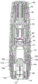
Fig. 2 is a cross-sectional view through the autoinjector 1 of fig. 1. Fig. 3 is a second cross-sectional view through the autoinjector of fig. 1, at 90 degrees from the cross-section of fig. 2.
The autoinjector 1 shown in figures 1, 2 and 3 comprises: a medicament container assembly (shown in figures 4a and 4 b); a power unit assembly (partially shown in fig. 6a, 6b and 7) including an end of a transport noise generating mechanism (shown in fig. 8 and 9); an inner housing (shown in fig. 11) referred to herein as a chassis; a skin sensor assembly comprising a skin sensor element (shown in fig. 10) and a skin sensor spring; a lower housing (shown in fig. 12); an outer housing and a cap (shown in fig. 14).
The medicament container assembly 10 is held within the chassis 120 and moves through the chassis in operation. The drug container assembly 10 is held in the initial position by a latch 122 on the chassis that engages a boss 13 on the drug container and prevents release of the drug container by the skin sensor assembly. The skin sensor assembly includes a skin sensor element 112 and a skin sensor spring 114. The skin sensor element is held by a latch element 112 on the chassis 120 and urged away from the drug container assembly 10 by a skin sensor spring 114 held between the chassis 120 and the skin sensor element 112. The lower housing 140 engages the chassis 120 by clamping to the window portion 130 of the chassis. Lugs 148 on the lower housing engage recesses 24 formed in the outer housing. The cap 30 engages the recess 142 on the lower housing and covers the skin sensor element 112.
The medicament container assembly is shown separately in fig. 4 a. Fig. 4b is a cross-sectional view of fig. 4 a. The medicament container assembly comprises a medicament container 10 containing a medicament to be delivered to a patient by injection, with a hypodermic needle 12 secured to the forward end. The drug container is formed of a cyclic olefin having excellent drug contact properties. The use of plastic drug containers has several advantages over glass. The plastic container may be molded with features forming part of the automatic injection and drug delivery mechanism, as described below with respect to this embodiment, and can be formed with much higher precision than glass. The plastic container may also withstand higher impact forces and pressures to allow for the use of stronger springs in the automatic injector mechanism and to allow for shorter, thicker medicament containers.
A plunger 14 is provided within the medicament container. Movement of the plunger 14 within the medicament container 10 pushes medicament out through the needle 12. The plunger is designed to provide low friction with the walls of the medicament container and to minimize any residence between the plunger and the medicament container. The plunger is a cap-seal type plunger configured such that a component of fluid pressure exerted on the plunger by the medicament is directed toward a sealing interface between the plunger and an inner surface of the medicament container as the plunger moves through the medicament container. A plunger of this type is described in GB 2467904. The peripheral portion of the plunger 14 that contacts the wall of the medicament container comprises a substantially non-elastic material. The inner surface of the forward end of the medicament container 10 is shaped to match the shape of the forward end of the plunger 14 to maximise the amount of medicament that is pushed out of the medicament container during use.
A sealing foil 16 is provided at the rear end of the medicament container 10 to ensure that the medicament is maintained and maintained in a sterile and intact state. The sealing foil 16 may be a laminated foil comprising an aluminium layer and may be welded or glued to the rear end of the medicament container 10.
In this embodiment, the hypodermic needle 12 is glued into the needle hub portion 11 of the medicament container 10. However, the medicament container may be moulded around the needle. The needle is covered by a needle shield 50 which maintains the sterility of the needle 12. As shown in fig. 4b, the needle shield 50 comprises a rigid outer housing 52 forming a seal with the needle hub portion 11. A flexible member in the form of an elastomeric stopper 54 is provided within the needle shield into which the forward end of the needle 12 is inserted. The elastomeric stopper seals the needle and ensures that no medicament can escape from the needle before the needle shield is removed. The rigid outer housing 52 of the needle shield may be transparent, allowing inspection of the needle during assembly of the autoinjector. The front end of the rigid outer housing 52 includes a ridge 56 configured to engage the hook 32 in the cap 30, as shown in fig. 2. This ensures that the needle shield is removed with the cap when the cap 30 is removed.
The sealing of the needle shield to the needle hub 11 is shown in detail in fig. 5, which is a close-up view of a part of fig. 4 b. The needle hub 11 is cylindrical in shape, wherein it is surrounded by a needle shield. The rigid body 52 of the needle shield has a pair of ribs 57, 58 extending around the inner surface of the needle shield. The ribs have an interference fit with the needle hub 11 to provide a seal that maintains the sterility of the needle. In this example, the joint has a diameter of 2.4mm and a certain surface finish quality, wherein the maximum distance between the peaks and valleys is not more than 2 μm. The needle hub may be formed from a moulded plastics material such as a cyclo olefin polymer. The surface finish of the needle hub is designated 0.2 Ra. The needle hub may have a cylindrical outer surface to which the rigid body is coupled. The inner surface of the rigid body is specified to have a surface finish of 0.2Ra or less. The inner surface of the rigid body may have a surface finish with a maximum distance between peaks and valleys of 2 μm or less. The ribs have a nominal sealing diameter of 2.2 mm. There is a nominal diameter interference of 0.2mm between the needle hub 11 and the needle shield 50.
The rigid body of the needle shield is formed of polyethylene and has the same surface finish as the needle hub. The ribs 57, 58 are spaced 3mm from each other. In order to provide the maximum contact pressure between the rib and the needle hub in combination with the minimum force, and thus the closest seal with the minimum removal force, the contact area between the rib and the needle hub should be as small as possible. However, the contact area is limited by the manufacturing process of the needle shield and the materials used. In this example, the radius of curvature of each rib at the point of contact is preferably less than 0.6mm prior to fitting the rigid body to the needle hub. The contact point of each rib is a point on the surface of the rib configured to first contact the needle hub when the rigid body is assembled to the needle hub. However, in particular if the plastic is deformed by interference, the final contact radius may be greater than this value.
The autoinjector shown in figures 1 to 3 also includes an automatic mechanism for inserting the needle into the injection site and for injecting the drug through the needle into the injection site. The automated mechanism is referred to herein as a power unit assembly. The power unit assembly includes a stored energy source in the form of compression springs 61, 62. When the first spring 61, referred to as the insertion spring, is released, it moves the medicament container 10 through the housing of the autoinjector to insert the needle 12 into the injection site. The second spring 62, referred to as the delivery spring, is then released to move the plunger 14 through the drug container 10 to inject the drug. The springs 61, 62 and the mechanism for controlling the release sequence of the springs within the power unit assembly are positioned behind the drug container.
The power unit includes a power unit housing 64 coupled to the medicament container 10. The power unit housing in this embodiment comprises two parts, a lower power unit housing 65 and an upper power unit housing 66. The power unit housing is split into two parts to simplify assembly of the autoinjector, but in use the two parts are fixed to each other and act as a single component. The lower power unit housing 65 is clamped to the medicament container 10. The lower power unit housing 65 engages the recess 17 on the medicament container. Prior to use of the autoinjector, the insertion spring 61, in a compressed state as shown in fig. 2 and 3, is positioned between the upper power unit housing 66 and the retaining device 100. The retaining device 100 is coupled to the upper power unit housing 66 to retain the insertion spring 61 in the first compressed state, as explained with reference to fig. 7.
The delivery spring 62 is positioned between the upper power unit housing 66 and the multi-part drive element 70. When released, the delivery spring 62 drives the drive element 70 forward relative to the power unit housing 64 and thus drives the plunger 14 through the medicament container 10 to inject medicament, as described in detail below.
Prior to use of the autoinjector, a delivery spring 62 is positioned around insertion spring 61. Nested dual spring mechanisms in this manner have many advantages. First, by nesting one spring within another, the length of the autoinjector is minimized. Second, the delivery spring may be made larger than the insertion spring. The force required to inject the drug through the needle is typically much greater than the force required to insert the needle into the injection site. It is advantageous to use a smaller spring for needle insertion.
The rear end of the power unit assembly is shown in detail in fig. 6a and 6 b. FIG. 6a is a first cross-sectional view through the power unit assembly and shows the insertion spring seated on a first ledge 67 formed on the upper power unit housing 66. FIG. 6b is a second cross-sectional view through the power unit assembly at ninety degrees to the cross-sectional view of FIG. 6a and showing drive element 70 retained by a second ledge 69 formed on the upper power unit housing.
The power unit assembly is assembled as a separate component prior to its coupling to the drug container and the rest of the automatic injector. To maintain the insertion spring and the delivery spring in a compressed state, the power unit housing engages the retention device 100. The retaining device includes a head portion 106 and a shaft portion 108 extending from the head portion within the power unit housing 64 and the drive element 70. The shaft portion 108 ensures that the drive element 70 and in particular the lobes 86 on the second drive element 80 cannot be disengaged from the ledges 69 on the power unit housing until the drive element is moved away from the shaft portion 108.
FIG. 7 is a partial, perspective top view of the power unit assembly showing the retaining device 100 engaging the upper power unit housing 66. The insertion spring 61 urges the power unit housing away from the retaining means 100, but it is retained by the engagement of the surface 102 on the retaining means below the ledge 68 formed on the upper power unit housing. The power unit housing is released from the retaining device 100 by relative rotation between the power unit housing and the retaining device. In particular, a cam surface 104 is formed on the retaining device such that when the power unit assembly is inserted into the outer housing, a cam surface or projection 25 within the outer housing engages a cam surface on the retaining device and forces the retaining device to rotate. The power unit housing is prevented from rotating relative to the outer housing by engagement of the power unit housing with the chassis and engagement of the chassis with the outer housing. Rotation of the retaining device 100 moves the surface 102 out of engagement with the ledge 68, thereby disengaging the power unit housing from the retaining device.
Once the power unit housing has been released from retaining device 100, it is prevented from fully expanding by the engagement of outer housing 20 with lower housing 140, the engagement of lower housing 140 with chassis 120, the engagement of chassis 120 with drug container 10, and the engagement of drug container 10 to power unit housing 64. The outer housing 20 is configured to engage the lower housing 140 as it drives the retaining device 100 out of engagement with the power unit housing by rotating the retaining device.
As described above, the insertion spring 61 engages the ledge 67 on the upper power unit housing 66 to drive the power unit housing and drug container assembly forward through the chassis as it expands. The drive spring 62 engages the power unit housing 64 and the drive member 70 to drive the drive member and plunger through the medicament container. The drive element 70 comprises three components. Specifically, the drive spring engages a spring-loaded surface 72 on the first drive element 71. The first drive element 71 is coupled to the second drive element 80 and the third drive element 90. A multi-element drive element 70 is shown in fig. 8 and 9.
The drive element 70 is shown in fig. 8 in an initial configuration prior to delivery of medicament from the medicament container. The first drive element 71 is a substantially cylindrical tube in which the second drive element 80 is located. The first impact surface 75 on the first drive element is kept separate from the first impact surface 85 on the second drive element by the engagement of the first drive element with teeth 84 extending from the first impact surface on the second drive element towards the first drive element. The second drive element comprises a foil contact surface 82 configured to contact and pierce a sealing foil 16 on the medicament container 10. The foil contact surface 82 includes a plurality of serrations to assist in puncturing the foil seal. The second drive element 80 extends from the first impact surface 85 through the first drive element.
The second drive element is formed of moulded plastics material and is divided at its rear end into a pair of flexible legs 87 at the rear end of each of which is formed a lobe 86 for engagement with the power unit housing. A bore 88 is defined between the legs into which a shaft portion 108 of the retaining device is received. The shaft portion of the retaining device prevents the legs 87 from deflecting inwardly to disengage from the ledges 69 on the upper power unit housing.
The first drive element 71 includes a cutout 73 sized to receive the teeth 84 of the second drive element such that the first striking surface 75 on the first drive element contacts the first striking surface 85 on the second drive element. In order for the teeth 84 to be received in the notches 73, the first drive element must rotate relative to the second drive element. However, in the initial position, this is prevented by the third drive element 90. In the initial position, the third drive element 90 engages both the first drive element and the second drive element. The third drive element in this embodiment is generally tubular and is positioned between the first drive element and the second drive element. The projection 92 on the third drive element engages the slot 74 formed in the first drive element to prevent relative rotation of the first and third drive elements. The slot is dimensioned to allow axial movement between the first drive element and the third drive element, i.e. movement in the direction of travel of the drive elements when the drive spring expands. The cut-outs 94 in the third drive element engage the teeth 84 on the second drive element to prevent relative rotation between the second and third drive elements. However, the third drive element is free to move axially relative to the second drive element.
The projection 92 on the third drive element engages the rear surface of the medicament container 10 when the drive element has reached the end of its forward stroke through the medicament container. The third drive element is thus held by the medicament container as the first and second drive elements continue to move forward under the influence of the drive spring 62. When the cutout 94 in the third drive element disengages from the tooth 84 due to such relative axial movement between the third drive element and the second drive element, the first drive element 71 is free to rotate relative to the second drive element 80. The teeth 84 engage the first drive element on the angled surface 76 such that the action of the drive spring on the first drive element 71 forces it to rotate relative to the second drive element. When the teeth 84 are free to enter the cut-outs 73, the first drive element moves forward rapidly relative to the second drive element because there is no significant resistance to this forward movement. The first impact surface on the first drive element then impacts the first impact surface on the second drive element at high speed, producing an acoustic signal indicating that the drive element has reached the end of its stroke. The final position is shown in fig. 9.
The principle of operation of this "end of delivery" indication is to use a two-part drive element in which the two parts move together until at or near the end of travel of the drive element, whereby the two parts are free to move relative to each other under the influence of the stored energy source to produce an acoustic signal. It is advantageous to use the same energy source as the one used for driving the drive element through the medicament container. However, it should be clear that there are several options for the mechanism for locking and releasing the two parts of the drive element, which is implemented using a third drive element in the embodiment of fig. 8 and 9. For example, when the first drive element reaches a particular position within the power unit housing, features within the power unit housing may be provided to force the first drive element to rotate relative to the second drive element.
The skin sensor assembly is arranged before the medicament container, it covers the needle both before and after use and it allows to start the autoinjector simply by removing the cap and pressing the autoinjector against the injection site.
The skin sensor assembly includes a skin sensor element 112 shown in fig. 10, and a skin sensor spring 114 held between the skin sensor element and the chassis. This can be clearly seen in fig. 3. In operation, the skin sensor element interacts with the chassis 120 shown in fig. 11 and the lower housing 140 shown in fig. 12.
Fig. 11 is a perspective view of the chassis 120. The chassis is formed of a transparent plastics material and includes two window portions 120 which are aligned with the windows 22 formed in the outer housing 20. The lower housing 140 is clamped to the chassis around the window portion 130 as shown in fig. 13 a. The latches 122 are formed such that they can flex outwardly out of engagement with the medicament container 10. The chassis has a reduced diameter front end 132 that prevents the medicament container from advancing beyond the insertion location. A bearing surface 133 is provided against which the skin sensor spring 114 rests.
The chassis 120 also includes a flexible arm 121 formed below the window portion 130. The flexible arms 121 each comprise a ridge 123 at their free ends abutting the rear end of the skin sensor element 112. The ridge 123 (in combination with the cap and/or the upper housing) prevents the skin sensor element from moving backwards to a position where the latch 122 can release the medicament container 10, as described with reference to fig. 15.
The chassis also includes a latch element 124. Each latch element 124 comprises a flexible arm 125 extending from the body of the chassis towards the front end of the device, and a hook 126 and cam head 128 on the end of the flexible arm. Hook 126 is configured to engage skin sensor element 112. Cam head 128 is positioned inwardly from the hook and is configured to engage power unit housing 64. In the context of this document, inward is with respect to the outer housing. The latch elements 124 on the chassis do not extend inwardly from the surrounding portion of the chassis to engage the power unit or skin sensor elements. This is advantageous from a moulding point of view.
Fig. 12 is a perspective view of the lower case 140. The lower housing is secured to the chassis by clamping the portion 146 around the window portion 130 of the chassis. The lower housing 140 includes a pair of second latch elements 144 that are received in the openings 115 of the skin sensor element 112 in an initial position. The lower housing includes a recess 142 for engaging the cap 30. The surface 145 serves to limit movement of the skin sensor beyond the fully extended position, as will be described. The lower housing further comprises a slot 141 in which the flexible arms 121 of the chassis are received. Lugs 148 on the lower housing engage recesses 24 formed in the outer housing.
In the initial position, prior to use, and as shown in fig. 2 and 3, the skin sensor element 112 is urged away from the chassis by the skin sensor spring 114. It is held to the chassis by the engagement of surface 116 with latch element 124. In the initial position, the second latch element 144 on the lower housing is received in the opening 115 of the skin sensor element 112.
Fig. 13a-13d show the operational sequence of the skin sensor assembly and are side views of the device with the outer housing and cap removed. Figure 13a shows the device with the cap removed but before use. The skin sensor element 112 is held by the latch element 124 against the action of the skin sensor spring. Specifically, hook 126 on latch element 124 engages surface 114 on the skin sensor element.
Fig. 13b shows the skin sensor element 112 pushed backwards, just as the skin sensor element is pressed against the injection site. In this position, hook 126 is clear of surface 116. The second latch element 144 is still received in the opening 115 of the skin sensor element. However, the wider portion of the opening 115 is now aligned with the position of the latch 122 on the chassis. In the position shown in fig. 13b, the latches 122 no longer hold the medicament container 10, as they may be pushed outwards into the opening 115 in the skin sensor element. Thus, the medicament container is free to move forward and the insertion spring 61 expands to move the power unit assembly and the medicament container to the inserted position, as shown in fig. 13 c.
In fig. 13c the medicament container is in the inserted position and the needle 12 extends significantly beyond the skin sensor element 112. In this position, the power unit assembly has moved forward so that the lugs 63 on the power unit housing 64 (only the upper end of which is visible in FIG. 2) have pushed against the cam heads 128 and thus have deformed the arms 124. As the arms move forward, the deformation of arms 124 moves hook 126 out of the path of surface 116.
The skin sensor spring pushes the skin sensor element forward when the device is removed from the injection site. As the arms deform, surface 116 may move past hook 126. The skin sensor element can then be moved to a fully extended position, as shown in fig. 13 d. In this position, the skin sensor element covers the needle again. The skin sensor element is held to the chassis and prevented from moving further forward by a surface 117 on the skin sensor element abutting a surface 145 on the lower housing. The second latch element 144 engages the aperture 118 in the skin sensor element 112 to prevent the skin sensor element from moving backwards against the skin sensor spring. When the skin sensor element is moved to its fully extended position, the second latch element may ride on an inclined surface 119 on the skin sensor element to snap into the aperture 118, whereby the skin sensor element is locked in the fully extended position.
The latching mechanisms for the skin sensor and for holding and releasing the drug container are all positioned on two opposite sides of the device. This allows the window 22 to remain unobstructed throughout operation of the device. This allows for easy inspection of the drug prior to use and for viewing the progress of drug delivery through the window 22.
The device shown in figures 1 to 13 includes a mechanism to prevent activation prior to removal of the cap. Fig. 14 is a perspective view of the cap 30. The cap is formed of a molded plastic material and includes a protrusion 34 configured to engage a recess 142 on the lower body, as shown in fig. 2. The upstanding central tube includes a hook portion 32, shown in fig. 2, for retaining the needle shield. The cap also includes a tongue 36 which extends in the space between the outer housing and the chassis when the cap is fitted to the device, as shown in figure 3.
Fig. 15 is a detail of the front end of the device shown in fig. 3. It can be seen that the tongue 36 on the cap is an adjacent flexible arm 121 formed on the chassis and shown more clearly in figure 11. The flexible arm 121 comprises a ridge 123 abutting the rear end of the skin sensor element 112. The bulge 123 prevents the skin sensor element from moving backwards to a position where the latch 122 can release the medicament container 10. Thus, when the cap is engaged to the lower housing 140, the device cannot be activated.
When the cap is removed, the arms 121 can be pushed outwards by the skin sensor element into the space vacated by the tongue 36 as if the skin sensor were moved backwards. The skin sensor element and the elevation 123 are shaped to allow this to occur smoothly. The lower housing includes an aperture 141 into which the arm 123 can deflect.
Fig. 16a to 16g show the sequence of operation of the device of the first embodiment. Fig. 16a to 16g are cross-sectional views similar to fig. 2, but with the cap removed.
Fig. 16a shows the device just after the cap has been removed, but before the skin sensor element is pressed against the injection site. It can be seen that the needle shield assembly has been removed together with the cap.
Fig. 16b shows the device with the skin sensor element pushed backwards. A second latch element 144 on the lower housing prevents further rearward movement of the skin sensor. In this position, the latch 122 on the chassis is free to flex into the window 115, but has not yet done so.
Fig. 16c shows the medicament container 10 and the power unit housing 64 moved to the insertion position by expansion of the insertion spring 61. In this position, the needle 12 is inserted into the injection site. The second drive element 80 is just off the shaft portion 108 of the holding device 100. This means that the legs 87 can be squeezed together to disengage the lugs 86 from the surface 69 on the power unit housing 64. The protrusion 63 on the power unit housing has deflected the latch arm 124 so that the skin sensor element 112 is free to move forward to the fully extended position once removed from the injection site.
Fig. 16d shows the drive element disengaged from the power unit housing and at the first contact point of the drive element with the sealing foil. The drive spring is expanding to urge the drive element forward.
Fig. 16e shows the drive spring expanded further and the drive element further forward. The foil has been ruptured and the plunger has moved through the medicament container and almost all the medicament has been injected. At this point, the third drive element has engaged the rear end of the medicament container and is therefore moved rearwardly relative to the second drive element. In this position, the drive element is no longer engaged to the second drive element, and the second drive element can rotate relative to the first drive element, as described with reference to fig. 8 and 9.
Figure 16f shows the first drive element being driven forward onto the second drive element as the second drive element rotates, thereby providing an audible indication of the end of drug delivery. The plunger is in the fully forward position and the desired volume of medicament has been injected. At this point, the user may remove the device from the injection site.
Fig. 16g shows the device after it has been removed from the injection site with the skin sensor element in the fully extended position, locked and covering the needle. As described with reference to fig. 13d, the skin sensor element is held to the chassis and prevented from moving further forward by the surface 117 on the skin sensor element abutting the surface 145 on the lower housing. The second latch element 144 engages the hole 118 in the skin sensor element 112 to prevent the skin sensor element from moving backwards against the skin sensor spring.
As can be seen from fig. 2 and 16a-c, the drive element 70 and all other components of the device remain separated from the sealing foil 16 until the sealing foil is ruptured. Before use, the drive element 70 is kept at a predetermined distance from the sealing foil 16. The power unit housing 64 is fixed to the side of the medicament container and does not contact the sealing foil. The seal foil 16 remains untouched during the needle insertion phase of the operation. This arrangement ensures that the seal foil can be tested before the medicament container is assembled to the rest of the automatic injector and subsequently remains untouched until the medicament is delivered. This reduces the likelihood of contamination or loss of the drug prior to delivery.
Fig. 17 is a schematic diagram showing an assembly sequence of the automatic injector of the first embodiment. In step 150, the medicament container assembly 10 comprising the needle 12 and the needle shield 50 is filled with a dose of medicament and the plunger 14 and subsequently sealed by the sealing foil 16. This step is performed in a sterile environment. Independently, in step 152, the power unit assembly is assembled and the retaining device retains the drive and insertion springs in a compressed state. The filled drug container assembly is then assembled to the power unit assembly and the lower power unit housing clamped to the drug container 10 in step 154. In step 156, the front end of the device including the chassis, the skin sensor element, the skin sensor spring, and the lower housing are assembled. The cap is typically coupled to the front end assembly at this stage, but this is shown as a separate step 157. In step 158, the front end assembly is coupled to the drug container assembly and the power unit assembly. The medicament container assembly is retained by a latch arm on the chassis. In step 160, the outer housing is placed over the power unit assembly and engaged with the lower housing 140. Just before lugs 148 on the lower housing engage recesses 24 formed in the outer housing, cam surfaces 25 on the outer housing 20 engage the retaining device 100 and force the retaining device to rotate out of engagement with the power unit housing 64. When the power unit housing is disengaged from the retaining means, the insertion spring 61 is allowed to expand a small amount, but it is held in the second compressed state by the action of a latch 122 on the chassis engaging the medicament container 10. In the second compressed state, the insertion spring still stores sufficient energy to insert the needle 12 into the injection site by pushing the medicament container to the insertion position.
The cap 30 is typically assembled to the lower housing 140 during assembly of the front end assembly, but may be added after coupling the power unit and the front assembly or after the outer housing has been assembled to the lower housing. These selections are shown in fig. 17 as step 157.
At step 162, the autoinjector is fully assembled and ready for use. This production sequence has the advantage that the power unit assembly can be produced independently of the other components and transported and stored separately. Steps 156, 157, 158 and 160 are simple and easy to automate.
The first embodiment described also has the following advantages: the use of the same power unit assembly enables different lengths and shapes of outer housings to be used for different drugs. The feature 25 for rotating the retaining device out of engagement with the power unit housing 64 need not be manufactured with the same tight tolerances on the dimensions required for the shaft portion 108 of the retaining device. It is therefore a simple matter to provide different external housings to provide a distinctive appearance for a device for a particular medicament or a device associated with a particular brand. The user can then quickly identify whether they have the appropriate device. Different external housings may also be provided to accommodate different user populations that may have different specific requirements, for example, a user may have limited hand dexterity.
Figure 18 is a perspective view of an autoinjector 201 according to a second embodiment of the present invention prior to use. The autoinjector 201 includes an outer housing 220 having a viewing window 222 through which the drug within the autoinjector may be inspected. A cap 230 is provided to cover the needle insertion end of the device and prevent accidental activation of the device. The autoinjector is compact, about 10cm in length and fits easily in the user's hand.
Fig. 19 is a cross-sectional view through the autoinjector 201 of fig. 19. Fig. 20 is a second cross-sectional view through the autoinjector of fig. 19, at 90 degrees from the cross-sectional view of fig. 19.
The autoinjector 201 shown in fig. 18, 19 and 20 includes: a drug container assembly (shown in fig. 21), a power unit assembly comprising a power unit housing 264 (shown in fig. 27), a drive element 270, and insertion and drive springs 260, 262, an inner housing (shown in fig. 23) referred to herein as a chassis, a skin sensor assembly comprising a skin sensor element (shown in fig. 22) and a skin sensor spring, a lower housing (shown in fig. 26), an outer housing, and a cap (shown in fig. 25).
The medicament container assembly 210 is held within the chassis 320 and moves through the chassis in operation. The medicament container assembly 210 is held in the initial position by a latch 322 on the chassis which engages a boss 213 on the carrier 215 surrounding the medicament container 211. The latch 322 prevents the carriage from being released by the skin sensor assembly. The skin sensor assembly includes a skin sensor element 312 and a skin sensor spring 314. The skin sensor element is held by a latch element 324 on the chassis 320 and urged away from the drug container assembly 210 by a skin sensor spring 314 held between the chassis 320 and the skin sensor element 312. The lower housing 340 engages the chassis 320 by clamping to the T-shaped protrusion 328 on the chassis. The window portion 348 on the lower housing engages the window 222 formed in the outer housing. The cap 230 engages the channel 342 on the lower housing and covers the skin sensor element 312.
Fig. 21 is a perspective view of the medicament container assembly shown in fig. 19 and 20. The medicament container assembly comprises a medicament container 211 and a carrier element holding the medicament container 211 therein. The carrier and the medicament container may be formed as separate parts or may be co-moulded together. The drug container 211 contains a drug to be delivered to a patient by injection, and a hypodermic needle 212 is fixed to the front end. As in the first embodiment, the drug container is formed of a cycloolefin having excellent drug contact properties. The carrier may be formed of different materials and is advantageously formed of a moldable plastic. Gripping features 213 and 219 are formed on the carrier 215.
A plunger 214 is provided within the medicament container. Movement of the plunger 214 within the medicament container 211 forces medicament out through the needle 212. The plunger is of the same type as described with reference to the first embodiment and is designed to provide low friction with the wall of the medicament container and to minimise any stiction between the plunger and the medicament container. The inner surface of the front end of the medicament container 211 is also shaped to match the shape of the front end of the plunger 214 to maximize the amount of medicament that is pushed out of the medicament container during use.
A sealing foil 216 is provided at the rear end of the medicament container 211 to ensure that the medicament is maintained and maintained in a sterile and intact state. The sealing foil 216 may be a laminated foil comprising an aluminum layer and may be welded to the rear end of the medicament container 211.
As in the first embodiment, the hypodermic needle 212 is glued into the needle hub 217 of the medicament container 211. However, the medicament container may be moulded around the needle. The needle is covered by a needle shield 250 that maintains the sterility of the needle 212. As described in the first embodiment, needle shield 250 includes a rigid outer housing 252 that forms a seal with needle hub portion 217. An elastomeric stopper 254 is provided within the needle shield into which the forward end of the needle 212 is inserted. The elastomeric stopper seals the needle and ensures that no medicament can escape from the needle before the needle shield is removed. The rigid outer housing 252 of the needle shield may be transparent, allowing inspection of the needle during assembly of the autoinjector. The forward end of needle shield outer housing 252 includes a ridge 256 to engage hook 232 in cap 230, as shown in fig. 19. This ensures that the needle shield is removed with the cap when the cap 230 is removed.
The sealing of the needle shield to the needle hub is achieved using an interference fit in the same manner as described for the first embodiment and shown in figure 5.
As in the first embodiment, the autoinjector illustrated in fig. 18-20 also includes an automated mechanism for inserting the needle into the injection site and for injecting the drug through the needle into the injection site. The automated mechanism is referred to herein as a power unit assembly. The power unit assembly includes a stored energy source in the form of compression springs 260, 262. When the first spring 260, referred to as an insertion spring, is released, it moves the drug container assembly 210 through the housing of the autoinjector to insert the needle 212 into the injection site. A second spring 262, referred to as a delivery spring, is then released to move the plunger 214 through the drug container 211 to inject the drug. The springs 260, 262 and the mechanism for controlling the release sequence of the springs within the power unit assembly are positioned behind the drug container assembly.
The power unit includes a power unit housing 264 (shown in fig. 22) coupled to the drug container assembly 210. The power unit housing 264 has an arm 265 that clips to a feature 219 on the bracket 215. Prior to use of the autoinjector, the insertion spring 260, shown in fig. 19 and 20 in a compressed state, is positioned between the power unit housing 264 and the outer housing 220. When the drug container assembly is released from the latch 322 on the chassis, the drug container assembly is free to move forward through the chassis to the insertion position, urged by the expansion of the insertion spring 260, as will be described.
The drive element 270 includes a front end surface 276 which is serrated to assist in breaking the seal foil 216 and engaging the plunger in use, as will be described. The drive member 270 also has resilient legs 274 that are pressed outwardly by the locking surfaces 226 that are part of (or rigidly secured to) the main housing 20 so that the protrusions 272 engage the power unit housing and prevent disengagement from the locking surfaces 226. In this manner, the drive spring 262 is locked in a compressed state and moved with the power unit housing 264 until the boss 272 can be released from the surface 267.
When the power unit housing has traveled to the insertion position, the drive element has traveled beyond the locking surface 226. At this point, the legs 274 can be squeezed together to allow the drive element to disengage from the surface 267 on the power unit housing, since the locking surface is no longer between the legs 274. The drive element may then be moved forward by the drive spring 262 to break the seal foil 216 and push the plunger 214 through the medicament container 211 to dispense medicament through the needle 212.
As in the first embodiment, in the second embodiment the skin sensor assembly is provided in front of the medicament container, which covers the needle both before and after use and allows to simply start the autoinjector by removing the cap and pressing it against the injection site.
The skin sensor assembly includes a skin sensor element 312 and a skin sensor spring 314. The skin sensor spring 314 is held between the skin sensor element and the chassis. This can be clearly seen in fig. 19. In operation, the skin sensor element interacts with the chassis 320.
Fig. 23 is a perspective view of a skin sensor element of the second embodiment. The skin sensor element comprises a front surface 313 which in use contacts the injection site and has an aperture through which the needle passes during insertion of the needle. The holes 315 are arranged such that when the skin sensor elements are in the retracted position they align with the latches 322 on the chassis to allow the latches to deflect outwardly out of engagement with the features 213, releasing the drug container. The hook portion 316 is arranged to engage the chassis in an initial position, holding the skin sensor element against the force exerted by the skin sensor spring. When the skin sensor element is in the fully extended position, the surface 317 is arranged to abut the chassis and prevent retraction of the chassis. The support arms 318 provide mechanical rigidity.
Fig. 24 is a perspective view of the chassis of the second embodiment. The chassis is formed from a plastics material. The chassis is also substantially tubular with a central bore through which the medicament container can move axially. The chassis has a reduced diameter front end 332 beyond which the medicament container assembly cannot travel. At the forward end, the chassis includes a pair of cantilevers 334 that extend radially inward. The medicament container assembly contacts the cantilever arm when it is moved to the insertion position and deflects the cantilever arm in the insertion direction (also referred to herein as the axial direction). When the drug container assembly is moved to the insertion position, the deflection of the cantilever arm decelerates the drug container assembly reducing the force applied to the injection site from the chassis by the skin sensor spring and the skin sensor. The cantilever arms 334 are configured to extend rearwardly from their fixed end to their free end so that they can deflect before being flush with the remainder of the front end of the chassis.
The chassis includes a latch element 324 that engages a hook 316 on the skin sensor element. The latching elements 324 are resilient arms that extend rearwardly from their fixed ends, but extend at an angle offset from the axial direction. When the skin sensor is moved to the extended position, the latch element may be deflected by a cam feature 269 on the power unit assembly to allow the hook portion 316 to pass. The chassis includes locking arms 326 which are resilient arms extending forwardly from their fixed ends. The locking arm may flex to allow the skin sensor element to pass when the skin sensor is moved from the retracted position to the extended position, but the locking arm is configured to prevent the surface 317 from passing back over the locking arm 326 once the skin sensor has reached the fully extended position.
Fig. 25a-25c show the operational sequence of the skin sensor assembly and are side views of the device with the outer housing and cap removed. Figure 25a shows the device before use. The skin sensor element 312 is held against the action of the skin sensor spring by the locking element 324. Specifically, the hook 316 on the skin sensor element engages the locking element 324.
Fig. 25b shows the skin sensor element 312 pushed backwards as if the skin sensor element were pressed against the injection site and the power unit moved forward. In this position, the hook 316 is clear of the surface latch element 324. The hole 315 is now aligned with the position of the latch 322 on the chassis. In the position shown in fig. 25b, the latches 322 no longer hold the medicament container assembly 210, as they may be pushed outwards into the hole 315 in the skin sensor element. Thus, the drug container 311 has moved forward and the insertion spring 261 expands to move the power unit assembly and the drug container to the inserted position.
When the power unit assembly is moved forward to the insertion position, the cam ridge 269 engages the latch elements 324 to deflect the latch elements so that they extend in the axial direction, as shown.
The skin sensor spring 314 pushes the skin sensor element 312 forward when the device is removed from the injection site. When the latch arm 324 is deflected, the hook portion 316 can pass the latch element 324 as the skin sensor element moves forward. The skin sensor element 312 can be moved to a fully extended position as shown in fig. 25 c. In this position, the skin sensor element covers the needle again. The skin sensor element is held to the chassis and prevented from moving further forward by the support arm 318 engaging a portion of the lower housing 340 (not shown in fig. 25 c). When the skin sensor is moved from the retracted position to the extended position, the locking arm 326 flexes to allow the skin sensor element to pass, but if the skin sensor element is pushed back towards the retracted position, the surface 317 then engages the locking arm 326 to lock the skin sensor in the extended position.
Fig. 26 is a perspective view of the lower housing of the second embodiment. The lower housing 340 is formed of a transparent plastic material and includes a window portion 348. The lower housing fits over the skin sensor and chassis but is partially within the outer housing. The window portion 348 has a raised outer edge that engages the window 222 formed in the outer housing. The lower housing 340 engages the chassis 320 by receiving the T-shaped projection 328 on the chassis through the aperture 344. The channel 342 on the lower housing is configured to engage the cap 330.
Fig. 27 is a perspective view of the cap of the second embodiment. Cap 230 includes a central cylindrical tube portion that includes three angularly spaced, inwardly projecting hooks 232 (shown in fig. 19) that can be pushed over and engage ridges 256 on needle shield 250. This ensures that the needle shield is removed with the cap when the device is to be used. The cap also includes three inwardly projecting lugs 234 equally spaced around the circumference on the cap that are configured to engage the lower housing 340. To remove the cap, the user simply grips and squeezes the cap between two fingers and pulls the cap away from the lower housing. The use of three equally spaced lugs ensures that when the cap is squeezed radially by a user, whichever direction the cap is squeezed in, at least two of the lugs will move outwardly to disengage from the lower housing. This ensures that the cap can be easily removed.
Fig. 28a to 28e are cross-sectional views of the second embodiment, showing the sequence of operation. Fig. 28a shows the device just after removal of the cap, but before pressing the skin sensor element against the injection site. It can be seen that the needle shield assembly has been removed together with the cap.
Fig. 28b shows the arrangement with the skin sensor element pushed backwards, compressing the skin sensor spring 314. The support arms 318 on the skin sensor element abut the chassis to prevent further rearward movement of the skin sensor. In this position, the latch 322 on the chassis is free to flex into the window 315.
Fig. 28c shows the drug container 211 and the power unit housing 264 moved to the insertion position by expansion of the insertion spring 261. In this position, the needle 212 is inserted into the injection site. The drive element 270 just clears the locking surface 226 on the outer housing. This means that the legs 274 can be squeezed together to disengage the lugs 272 from the surfaces 267 on the power unit housing 264. The drive spring 262 is free to expand. The cam boss 269 on the power unit housing has deflected the latch element 324 so that the skin sensor element 312 is free to move forward to the fully extended position once removed from the injection site.
Fig. 28d shows the drive spring 262 expanded. The seal foil 216 has ruptured and the plunger 214 has moved through the medicament container and the medicament has been injected.
Fig. 28e shows the device after it has been removed from the injection site with the skin sensor element in the fully extended position, locked and covering the needle. The skin sensor element is held to the chassis and prevented from moving further forward by the engagement of the support arms 318 with a portion of the lower housing 340. When the skin sensor reaches the extended position, the locking arm 316 has flexed to allow the skin sensor element to pass, but the surface 317 locks the skin sensor element in the extended position, preventing any retraction of the skin sensor element.
Fig. 29 is a schematic view showing an assembly process of the automatic injector according to the second embodiment of the present invention. In step 350, the medicament container assembly 210 comprising the needle 212 and the needle shield 250 is filled with a dose of medicament and the plunger 214 and then sealed by the sealing foil 216. This is performed in a sterile environment. Independently, in step 352, the power unit assembly is assembled to the outer housing. The filled drug container assembly is then assembled to the power unit assembly in step 354. In step 356, the front end of the device including the chassis, the skin sensor element, the skin sensor spring, and the lower housing are assembled. The power unit housing includes a locking arm 266 that is received in the opening 224 in the outer housing to hold the insertion spring in the first compressed state. The locking surface 226 engages the drive element 270 to maintain the drive spring in a compressed state.
In step 358, the front end assembly is coupled to the drug container assembly, the power unit assembly, and the outer housing. The medicament container assembly is retained by a latch arm on the chassis. The window portion 348 in the lower housing is clamped to the window 222 of the outer housing. When the lower housing is moving toward an engaged position where the window portion is fully engaged with the window on the outer housing, the chassis 320 engages the arms 266 on the power unit housing to move them out of the opening 224. This mechanism is shown in fig. 30.
The chassis includes a cam surface 336 at its rear end that engages a corresponding cam surface 267 on the locking arm 266. As the chassis and power unit move toward each other, the cam surfaces 267 on the chassis deflect the locking arms inwardly and out of engagement with the outer housing 220. At this point, insertion spring 260 is allowed to expand a small amount, but is then held in the second compressed state as long as lower housing 340 engages the outer housing. Latches 322 on the chassis engage the medicament container assembly 210, the chassis 320 is secured to the lower housing and the lower housing is secured to the outer housing. Thus, the insertion spring cannot expand until the latch 322 is released from the drug container. In the second compressed state, when the latch 322 is released, the insertion spring still stores sufficient energy to insert the needle 12 into the injection site by pushing the medicament container to the insertion position. The components are configured such that disengagement of locking arm 266 from the outer housing occurs only shortly before window portion 348 locks into window 222.
Claims (23)
1. A needle assembly, the needle assembly comprising:
a hypodermic needle;
a needle hub to which a needle is secured at a first end;
a needle shield coupled to the needle hub and covering the second end of the needle to provide a sterile barrier around at least a portion of the needle; wherein the needle shield comprises a rigid body; and
a flexible element at least partially encapsulated by the needle hub and the rigid body, the flexible element providing a liquid-tight seal around the second end of the needle,
wherein the rigid body is configured to provide an interference fit with the needle hub and thereby provide a seal around the needle hub.
2. A needle assembly according to claim 1, wherein the rigid body is formed from a moulded plastics material, for example high density polyethylene or polypropylene.
3. The needle assembly of claim 1, comprising at least one circumferential rib on an inner surface of said rigid body.
4. The needle assembly of claim 1 or 2, comprising at least one circumferential rib on an outer surface of the needle hub.
5. The needle assembly of claim 3, comprising at least two circumferential ribs on an inner surface of the rigid body.
6. The needle assembly of claim 5, wherein the radius of curvature at the contact point of each rib is less than 0.6mm prior to assembly of the rigid body to the needle hub.
7. A needle assembly according to any one of claims 1 to 3, wherein the needle hub has a surface finish with a maximum distance between the bump and the pit of 2 μm or less.
8. The needle assembly of any one of claims 1-3, wherein the needle hub has a cylindrical outer surface to which the rigid body is coupled.
9. A needle assembly according to any one of claims 1 to 3, wherein the needle hub is formed from a moulded plastics material, for example a cyclo olefin polymer.
10. The needle assembly of any one of claims 1-3, wherein the rigid body comprises an outer surface having at least one protrusion or recess.
11. The needle assembly of any one of claims 1 to 3, wherein at least a portion of the rigid body is transparent.
12. The needle assembly of any one of claims 1 to 3, wherein the flexible element is retained in the rigid body by at least one boss of the rigid body.
13. A needle assembly according to any one of claims 1 to 3, comprising at least one vent in the flexible element or the rigid body for allowing air to escape from the rigid body during insertion of the flexible element into the rigid body.
14. An autoinjector or syringe comprising a needle assembly according to any of claims 1 to 3.
15. An autoinjector or syringe according to claim 14, wherein autoinjector or syringe includes a cap and the needle assembly includes a ridge configured to engage with the cap to ensure that the needle shield is removed when the cap is removed.
16. A method of manufacturing a needle assembly, the method comprising:
a fixing step of fixing the first end of the needle to the needle hub;
a coupling step of coupling a needle shield to the needle hub, the needle shield covering the second end of the needle;
wherein the needle shield comprises a rigid body configured to provide an interference fit with the needle hub and thereby provide a seal around the needle hub and a flexible element, the needle shield providing a sterile barrier around at least a portion of the needle, the coupling step comprising inserting the second end of the needle into the flexible element such that the flexible element provides a liquid-tight seal around the second end of the needle.
17. A drug delivery device, the drug delivery device comprising:
a housing;
a medicament container; and
a power unit assembly coupled to the drug container, the power unit assembly comprising:
a stored energy source configured to release energy by expanding from a compressed state;
an insert element engaging the stored energy source and positioned between the stored energy source and the drug container; and
a retaining device that engages the stored energy source and the insertion element in a first position to retain the stored energy source in a first compressed state;
wherein the retaining device and housing are configured such that when the power unit assembly is engaged with the housing the retaining device is moved by the housing to a second position in which the retaining device is disengaged from the stored energy source or the insertion element;
the medicament container and housing are configured such that the stored energy source is held in a second compressed state by the medicament container when the retaining means is moved to the second position, an
A trigger mechanism configured to release the stored energy source from the second compressed state when an autoinjector is to be used.
18. A method for assembling a drug delivery device according to claim 17, the method comprising the steps of:
placing or forming a stored energy source in a power unit assembly having a power unit housing;
maintaining the stored energy source in the power unit assembly in a first compressed state using a retaining device coupled to a drive element and the power unit housing in a first position;
coupling the power unit assembly to a drug container assembly containing a drug to be dispensed by an automatic injector;
coupling the power unit assembly and the drug container assembly to an outer housing; and
moving the retaining means to a second position to release the stored energy source to a second compressed state, wherein the medicament container assembly and outer housing retain the stored energy source in the second compressed state, the stored energy source storing sufficient potential energy in the second compressed state for needle insertion and/or medicament injection when an autoinjector is to be used.
19. A drug delivery device, the drug delivery device comprising:
a device housing;
a drug container within the device housing and containing a drug and a plunger positioned within the drug container, the drug container having an outlet for dispensing the drug; and
a power unit assembly, the power unit assembly comprising: an insertion element secured to or abutting the medicament container, a first stored energy source positioned between the insertion element and the device housing, and a second stored energy source positioned between the insertion element and a drive element, wherein, in use, the drive element is configured to engage the plunger, the first stored energy source being at least partially located within the second stored energy source in an initial position.
20. A drug delivery device, the drug delivery device comprising:
a medicament container;
an inner housing;
an insertion mechanism coupled to the drug container and configured to move the drug container through the inner housing in an insertion direction;
a skin sensor element configured to contact an injection site in use; and
a skin sensor biasing element that biases the skin sensor element in an insertion direction;
wherein the skin sensor element is movable from an initial position to a retracted position in a direction opposite to the insertion direction to trigger the insertion mechanism;
wherein the inner housing comprises a first latch element to limit movement of the skin sensor element from the initial position in an insertion direction, the first latch element comprising a latch surface to engage the skin sensor element, and a first cam surface; and is
Wherein the drug container or the insertion mechanism comprises a second cam surface configured to engage the first cam surface to move the first latch element when the drug container is moved through the inner housing, thereby allowing the skin sensor element to move past the initial position to an extended position in an insertion direction.
21. A drug delivery device, the drug delivery device comprising:
a drug container assembly comprising a drug container containing a drug, a hypodermic needle coupled to the drug container and through which the drug can be dispensed, and a plunger within the drug container;
an inner housing within which the medicament container is positioned and through which the medicament container is movable;
a power unit assembly including at least one stored energy source, the power unit assembly coupled to the drug container;
a lower housing fixed to the inner housing;
an upper housing secured to the lower housing and enclosing the power unit assembly;
a skin sensor element extending between the lower housing and the inner housing and movable relative to the inner housing and the lower housing; and
a cap covering the skin sensor element and coupled to the lower housing.
22. A drug delivery device, the drug delivery device comprising:
a housing;
a medicament container within the housing, the medicament container having a first end,
a power unit assembly configured to move the medicament container in an axial direction through the housing from an initial position to an insertion position,
wherein the housing comprises a stop surface configured to engage the medicament container when the medicament container reaches the insertion position, the stop surface being provided on at least one resilient beam on the housing, the resilient beam being deflectable in an axial direction.
23. A drug delivery device, the drug delivery device comprising:
a housing;
a medicament container within the housing and containing a medicament to be dispensed, the medicament container having a first end defining a first opening;
a plunger positioned within the drug container and in contact with the drug;
a first sealing element providing a first closure seal over a first opening of the medicament container;
a push rod initially located on an opposite side of the first closure seal from the plunger, wherein the push rod is operable to break the first closure seal and move the plunger within the medicament container to dispense medicament; and
or the drug delivery device further comprises an insertion mechanism configured to move the drug container through the housing, and prior to use, the push rod and the insertion mechanism remain out of contact with the first sealing element;
or no element of the insertion mechanism and housing contacts the first sealing element as the medicament container moves through the housing.
Applications Claiming Priority (3)
| Application Number | Priority Date | Filing Date | Title |
|---|---|---|---|
| GBGB1313782.3A GB201313782D0 (en) | 2013-08-01 | 2013-08-01 | Drug delivery device |
| GB1313782.3 | 2013-08-01 | ||
| CN201480054227.2A CN105636623B (en) | 2013-08-01 | 2014-07-25 | Medicine delivery device |
Related Parent Applications (1)
| Application Number | Title | Priority Date | Filing Date |
|---|---|---|---|
| CN201480054227.2A Division CN105636623B (en) | 2013-08-01 | 2014-07-25 | Medicine delivery device |
Publications (1)
| Publication Number | Publication Date |
|---|---|
| CN113577459A true CN113577459A (en) | 2021-11-02 |
Family
ID=49223997
Family Applications (3)
| Application Number | Title | Priority Date | Filing Date |
|---|---|---|---|
| CN201480054227.2A Active CN105636623B (en) | 2013-08-01 | 2014-07-25 | Medicine delivery device |
| CN202111017968.1A Pending CN113577459A (en) | 2013-08-01 | 2014-07-25 | Drug delivery device |
| CN201910301065.2A Active CN109966594B (en) | 2013-08-01 | 2014-07-25 | Drug delivery device |
Family Applications Before (1)
| Application Number | Title | Priority Date | Filing Date |
|---|---|---|---|
| CN201480054227.2A Active CN105636623B (en) | 2013-08-01 | 2014-07-25 | Medicine delivery device |
Family Applications After (1)
| Application Number | Title | Priority Date | Filing Date |
|---|---|---|---|
| CN201910301065.2A Active CN109966594B (en) | 2013-08-01 | 2014-07-25 | Drug delivery device |
Country Status (6)
| Country | Link |
|---|---|
| US (3) | US10207051B2 (en) |
| EP (2) | EP3027247B1 (en) |
| JP (4) | JP6495904B2 (en) |
| CN (3) | CN105636623B (en) |
| GB (1) | GB201313782D0 (en) |
| WO (1) | WO2015015170A1 (en) |
Families Citing this family (39)
| Publication number | Priority date | Publication date | Assignee | Title |
|---|---|---|---|---|
| EP2195052B1 (en) | 2007-10-02 | 2019-09-04 | Medimop Medical Projects Ltd. | External drug pump |
| EP2399635A1 (en) | 2010-06-28 | 2011-12-28 | Sanofi-Aventis Deutschland GmbH | Auto-injector |
| EP2923714A1 (en) * | 2014-03-28 | 2015-09-30 | Sanofi-Aventis Deutschland GmbH | Autoinjector triggered by skin contact |
| TWI689326B (en) * | 2014-08-06 | 2020-04-01 | 加拿大商複製細胞生命科學公司 | Injection devices |
| EP3274021B1 (en) | 2015-03-24 | 2024-02-14 | Kaleo, Inc. | Devices and methods for delivering a lyophilized medicament |
| TW201707744A (en) * | 2015-06-03 | 2017-03-01 | 賽諾菲阿凡提斯德意志有限公司 | Drug delivery device |
| JP6830067B2 (en) | 2015-06-30 | 2021-02-17 | カレオ,インコーポレイテッド | Automatic syringe that administers medication in a prefilled syringe |
| US10576207B2 (en) | 2015-10-09 | 2020-03-03 | West Pharma. Services IL, Ltd. | Angled syringe patch injector |
| CN112972833B (en) | 2015-10-09 | 2024-01-09 | 西医药服务以色列分公司 | Syringe needle cap remover |
| GB2545266B (en) | 2015-12-11 | 2018-08-08 | Oval Medical Tech Limited | Autoinjector with retracting needle |
| CN108430548B (en) * | 2015-12-30 | 2020-08-04 | 诺和诺德股份有限公司 | Mechanism for reducing the risk of contamination of a medicament |
| JP6885960B2 (en) | 2016-01-21 | 2021-06-16 | ウェスト ファーマ サービシーズ イスラエル リミテッド | Drug delivery device with visual indicators |
| WO2017127215A1 (en) | 2016-01-21 | 2017-07-27 | Medimop Medical Projects Ltd. | Needle insertion and retraction mechanism |
| WO2017127216A1 (en) | 2016-01-21 | 2017-07-27 | Medimop Medical Projects Ltd. | Force containment in an automatic injector |
| US11389597B2 (en) | 2016-03-16 | 2022-07-19 | West Pharma. Services IL, Ltd. | Staged telescopic screw assembly having different visual indicators |
| USD830538S1 (en) * | 2016-05-04 | 2018-10-09 | Nuance Designs Of Ct, Llc | Autoinjector |
| USD831822S1 (en) * | 2016-05-17 | 2018-10-23 | Nuance Designs Of Ct, Llc | Autoinjector |
| PT3622986T (en) | 2016-06-03 | 2021-05-31 | Shl Medical Ag | Medicament delivery device |
| US10773024B2 (en) * | 2016-06-09 | 2020-09-15 | Becton, Dickinson And Company | Drive assembly for drug delivery system |
| CN109562229B (en) | 2016-08-01 | 2021-07-13 | 西医药服务以色列有限公司 | Anti-rotation medicine barrel pin |
| EP3554620A4 (en) * | 2016-12-16 | 2020-07-15 | Sorrento Therapeutics, Inc. | Application device for a fluid delivery apparatus and method of use |
| CN110300608B (en) | 2016-12-16 | 2021-10-19 | 索伦托治疗有限公司 | Fluid delivery device with suction mechanism and method of use |
| USD819197S1 (en) | 2016-12-16 | 2018-05-29 | Kimberly-Clark Worldwide, Inc. | Fluid delivery apparatus |
| US10603478B2 (en) | 2016-12-16 | 2020-03-31 | Sorrento Therapeutics, Inc. | Fluid delivery apparatus and method of assembly |
| AU2017376503B2 (en) * | 2016-12-16 | 2023-08-31 | Sorrento Therapeutics, Inc. | A fluid delivery apparatus having a controller assembly and method of use |
| KR20190088073A (en) | 2016-12-16 | 2019-07-25 | 소렌토 쎄라퓨틱스, 인코포레이티드 | Attachment band for fluid delivery device and method of using same |
| USD836774S1 (en) | 2016-12-16 | 2018-12-25 | Sorrento Therapeutics, Inc. | Cartridge for a fluid delivery apparatus |
| EP3554618B1 (en) * | 2016-12-16 | 2023-02-01 | Sorrento Therapeutics, Inc. | Fluid delivery apparatus including a microneedle assembly suitable for treating a migraine or cluster headache |
| CA3046228A1 (en) | 2016-12-23 | 2018-06-28 | Kaleo, Inc. | Medicament delivery device and methods for delivering drugs to infants and children |
| KR101811846B1 (en) * | 2017-03-15 | 2017-12-22 | 김휘화 | Safety improved semi-automatic syringe |
| US11819666B2 (en) | 2017-05-30 | 2023-11-21 | West Pharma. Services IL, Ltd. | Modular drive train for wearable injector |
| EP3727524A1 (en) * | 2017-12-18 | 2020-10-28 | Patients Pending Ltd. | Liquid delivery cap devices, systems, and methods |
| USD890332S1 (en) | 2018-02-08 | 2020-07-14 | Nuance Designs Of Ct, Llc | Autoinjector |
| EP3860683A1 (en) * | 2018-10-05 | 2021-08-11 | Phillips-Medisize A/S | Auto injector with automatic rigid needle shield remover |
| WO2020086752A1 (en) * | 2018-10-23 | 2020-04-30 | Aktivax, Inc. | Intranasal pressure drug delivery device |
| EP4009936A4 (en) | 2019-08-09 | 2023-08-09 | Kaleo, Inc. | Devices and methods for delivery of substances within a prefilled syringe |
| WO2022010726A1 (en) * | 2020-07-09 | 2022-01-13 | Eli Lilly And Company | Automatic injection device with reusable portion |
| WO2023222391A1 (en) * | 2022-05-18 | 2023-11-23 | Shl Medical Ag | A rotator for a medicament delivery device |
| EP4306151A1 (en) * | 2022-07-12 | 2024-01-17 | ALK-Abelló A/S | Autoinjector |
Citations (6)
| Publication number | Priority date | Publication date | Assignee | Title |
|---|---|---|---|---|
| US4735311A (en) * | 1986-04-09 | 1988-04-05 | The West Company | Needle shield assembly |
| JPH10305098A (en) * | 1997-04-23 | 1998-11-17 | Carl Zeiss:Fa | Needle cap device for disposable syringe |
| US6485474B1 (en) * | 1999-11-19 | 2002-11-26 | Schott Glas | Closure arrangement for a disposable syringe |
| US7771397B1 (en) * | 2009-05-26 | 2010-08-10 | Shl Group Ab | Needle cover assembly |
| US20120203186A1 (en) * | 2009-05-29 | 2012-08-09 | Patrick Vogt | Injection device with pricking protection and/or overload protection for a product container |
| US20130012886A1 (en) * | 2010-03-18 | 2013-01-10 | Daikyo Seiko, Ltd. | Syringe needle cap |
Family Cites Families (21)
| Publication number | Priority date | Publication date | Assignee | Title |
|---|---|---|---|---|
| US2551339A (en) | 1949-03-18 | 1951-05-01 | Abbott Lab | Administration of medicament |
| US5584815A (en) * | 1993-04-02 | 1996-12-17 | Eli Lilly And Company | Multi-cartridge medication injection device |
| SE9803662D0 (en) * | 1998-10-26 | 1998-10-26 | Pharmacia & Upjohn Ab | autoinjector |
| DE10028829A1 (en) * | 2000-06-10 | 2001-12-13 | Yilmaz Levent | Apparatus in the form of a hollow component for preparing, storing, and/or administering solutions comprises means for establishing a connection between its interior and a separate hollow component |
| JP2003199827A (en) * | 2001-12-28 | 2003-07-15 | Terumo Corp | Syringe |
| JP4578484B2 (en) * | 2004-01-23 | 2010-11-10 | ザ メディカルハウス リミテッド | Injection device |
| US7449012B2 (en) | 2004-08-06 | 2008-11-11 | Meridian Medical Technologies, Inc. | Automatic injector |
| DE102005058133A1 (en) | 2005-11-30 | 2007-05-31 | Schott Ag | Syringe, has sealing element and syringe body whereby annular, flexible deformable area can be pressed in sealing manner, by means of closing cap, on outer surface of cannula |
| DE102007013838A1 (en) * | 2007-03-22 | 2008-09-25 | Tecpharma Licensing Ag | Injection device with time-constant Ausschüttsignal |
| JP5916389B2 (en) * | 2009-02-06 | 2016-05-11 | ベクトン・ディキンソン・アンド・カンパニーBecton, Dickinson And Company | Lubricated pen needle |
| GB2467904B (en) | 2009-02-17 | 2013-06-12 | Oval Medical Technologies Ltd | Drug container and delivery mechanism |
| GB2471726B (en) * | 2009-07-10 | 2013-09-11 | Oval Medical Technologies Ltd | A pre-filled syringe including an oxygen absorber |
| JP5701889B2 (en) * | 2009-10-08 | 2015-04-15 | エス・ホー・エル・グループ・アクチボラゲットShl Group Ab | Drug supply device |
| JP6173210B2 (en) * | 2010-08-19 | 2017-08-02 | ノボ・ノルデイスク・エー/エス | Medical automatic injection device for manual needle insertion with needle shield, damping mechanism and auditory and tactile feedback |
| CN103118721A (en) * | 2010-09-24 | 2013-05-22 | 泰尔茂株式会社 | Method of assembling medicament injection device |
| GB201020475D0 (en) * | 2010-12-02 | 2011-01-19 | Oval Medical Technologies Ltd | Delivery mechanism for an autoinjector |
| GB201021764D0 (en) * | 2010-12-22 | 2011-02-02 | Owen Mumford Ltd | Autoinjectors |
| EP2489381A1 (en) * | 2011-02-18 | 2012-08-22 | Sanofi-Aventis Deutschland GmbH | Auto-injector |
| AU2012301784B2 (en) * | 2011-09-02 | 2017-02-16 | Unitract Syringe Pty Ltd | Drive mechanism for drug delivery pumps with integrated status indication |
| WO2013034958A1 (en) | 2011-09-07 | 2013-03-14 | Aselsan Elektronik Sanayi Ve Ticaret Anonim Sirketi | A battery system |
| CA2848143C (en) | 2011-09-09 | 2019-12-31 | Merck Patent Gmbh | An auto-injector for epinephrine injection |
-
2013
- 2013-08-01 GB GBGB1313782.3A patent/GB201313782D0/en not_active Ceased
-
2014
- 2014-07-25 CN CN201480054227.2A patent/CN105636623B/en active Active
- 2014-07-25 CN CN202111017968.1A patent/CN113577459A/en active Pending
- 2014-07-25 EP EP14744928.4A patent/EP3027247B1/en active Active
- 2014-07-25 WO PCT/GB2014/052282 patent/WO2015015170A1/en active Application Filing
- 2014-07-25 JP JP2016530597A patent/JP6495904B2/en active Active
- 2014-07-25 US US14/908,439 patent/US10207051B2/en active Active
- 2014-07-25 CN CN201910301065.2A patent/CN109966594B/en active Active
- 2014-07-25 EP EP22166909.6A patent/EP4088763A1/en active Pending
-
2018
- 2018-12-20 US US16/228,012 patent/US11058820B2/en active Active
-
2019
- 2019-03-07 JP JP2019041249A patent/JP6843909B2/en active Active
-
2021
- 2021-02-24 JP JP2021027858A patent/JP2021090826A/en active Pending
- 2021-06-10 US US17/344,333 patent/US20210299356A1/en active Pending
-
2023
- 2023-09-04 JP JP2023143296A patent/JP2023164935A/en active Pending
Patent Citations (6)
| Publication number | Priority date | Publication date | Assignee | Title |
|---|---|---|---|---|
| US4735311A (en) * | 1986-04-09 | 1988-04-05 | The West Company | Needle shield assembly |
| JPH10305098A (en) * | 1997-04-23 | 1998-11-17 | Carl Zeiss:Fa | Needle cap device for disposable syringe |
| US6485474B1 (en) * | 1999-11-19 | 2002-11-26 | Schott Glas | Closure arrangement for a disposable syringe |
| US7771397B1 (en) * | 2009-05-26 | 2010-08-10 | Shl Group Ab | Needle cover assembly |
| US20120203186A1 (en) * | 2009-05-29 | 2012-08-09 | Patrick Vogt | Injection device with pricking protection and/or overload protection for a product container |
| US20130012886A1 (en) * | 2010-03-18 | 2013-01-10 | Daikyo Seiko, Ltd. | Syringe needle cap |
Also Published As
| Publication number | Publication date |
|---|---|
| CN109966594A (en) | 2019-07-05 |
| JP2021090826A (en) | 2021-06-17 |
| EP3027247B1 (en) | 2022-05-11 |
| CN105636623A (en) | 2016-06-01 |
| JP2023164935A (en) | 2023-11-14 |
| JP2019103857A (en) | 2019-06-27 |
| US20160193412A1 (en) | 2016-07-07 |
| EP4088763A1 (en) | 2022-11-16 |
| JP2016525424A (en) | 2016-08-25 |
| EP3027247A1 (en) | 2016-06-08 |
| CN109966594B (en) | 2021-09-14 |
| JP6495904B2 (en) | 2019-04-03 |
| CN105636623B (en) | 2019-06-11 |
| GB201313782D0 (en) | 2013-09-18 |
| JP6843909B2 (en) | 2021-03-17 |
| US20190117893A1 (en) | 2019-04-25 |
| US10207051B2 (en) | 2019-02-19 |
| US11058820B2 (en) | 2021-07-13 |
| WO2015015170A1 (en) | 2015-02-05 |
| US20210299356A1 (en) | 2021-09-30 |
Similar Documents
| Publication | Publication Date | Title |
|---|---|---|
| CN109966594B (en) | Drug delivery device | |
| US20220233776A1 (en) | Automatic drug delivery devices | |
| KR101131099B1 (en) | Injection device | |
| US10166335B2 (en) | Drive assembly for an autoinjector and a method of assembling an autoinjector | |
| US10406288B2 (en) | Delivery mechanism for an autoinjector | |
| JP2020505202A (en) | Automatic syringe device | |
| JP7140850B2 (en) | pneumatic power pack | |
| WO2012073042A1 (en) | Needle insertion system for an autoinjector | |
| WO2013145998A1 (en) | Liquid administration set | |
| WO2004043514A2 (en) | Pre-filled retractable needle injection device | |
| GB2504128A (en) | Automatic injector with a skin contact element |
Legal Events
| Date | Code | Title | Description |
|---|---|---|---|
| PB01 | Publication | ||
| PB01 | Publication | ||
| SE01 | Entry into force of request for substantive examination | ||
| SE01 | Entry into force of request for substantive examination | ||
| WD01 | Invention patent application deemed withdrawn after publication |
Application publication date: 20211102 |