JP7140850B2 - pneumatic power pack - Google Patents
pneumatic power pack Download PDFInfo
- Publication number
- JP7140850B2 JP7140850B2 JP2020567480A JP2020567480A JP7140850B2 JP 7140850 B2 JP7140850 B2 JP 7140850B2 JP 2020567480 A JP2020567480 A JP 2020567480A JP 2020567480 A JP2020567480 A JP 2020567480A JP 7140850 B2 JP7140850 B2 JP 7140850B2
- Authority
- JP
- Japan
- Prior art keywords
- pressurized gas
- power pack
- pneumatic power
- rotating body
- bracket
- Prior art date
- Legal status (The legal status is an assumption and is not a legal conclusion. Google has not performed a legal analysis and makes no representation as to the accuracy of the status listed.)
- Active
Links
- 238000012377 drug delivery Methods 0.000 claims description 45
- 239000003814 drug Substances 0.000 claims description 25
- 230000004913 activation Effects 0.000 claims description 8
- 230000003213 activating effect Effects 0.000 claims description 5
- 239000012190 activator Substances 0.000 claims description 4
- 239000007789 gas Substances 0.000 description 80
- 238000002347 injection Methods 0.000 description 19
- 239000007924 injection Substances 0.000 description 19
- 229940079593 drug Drugs 0.000 description 15
- 238000000034 method Methods 0.000 description 6
- 238000004519 manufacturing process Methods 0.000 description 5
- 230000003993 interaction Effects 0.000 description 4
- 238000005259 measurement Methods 0.000 description 4
- 230000007246 mechanism Effects 0.000 description 3
- XKRFYHLGVUSROY-UHFFFAOYSA-N Argon Chemical compound [Ar] XKRFYHLGVUSROY-UHFFFAOYSA-N 0.000 description 2
- IJGRMHOSHXDMSA-UHFFFAOYSA-N Atomic nitrogen Chemical compound N#N IJGRMHOSHXDMSA-UHFFFAOYSA-N 0.000 description 2
- UCTWMZQNUQWSLP-UHFFFAOYSA-N adrenaline Chemical compound CNCC(O)C1=CC=C(O)C(O)=C1 UCTWMZQNUQWSLP-UHFFFAOYSA-N 0.000 description 2
- 230000008878 coupling Effects 0.000 description 2
- 238000010168 coupling process Methods 0.000 description 2
- 238000005859 coupling reaction Methods 0.000 description 2
- 230000000694 effects Effects 0.000 description 2
- 230000008569 process Effects 0.000 description 2
- UCTWMZQNUQWSLP-VIFPVBQESA-N (R)-adrenaline Chemical compound CNC[C@H](O)C1=CC=C(O)C(O)=C1 UCTWMZQNUQWSLP-VIFPVBQESA-N 0.000 description 1
- 229930182837 (R)-adrenaline Natural products 0.000 description 1
- CURLTUGMZLYLDI-UHFFFAOYSA-N Carbon dioxide Chemical compound O=C=O CURLTUGMZLYLDI-UHFFFAOYSA-N 0.000 description 1
- 229910052786 argon Inorganic materials 0.000 description 1
- 229910002092 carbon dioxide Inorganic materials 0.000 description 1
- 238000006243 chemical reaction Methods 0.000 description 1
- 238000010276 construction Methods 0.000 description 1
- 229960005139 epinephrine Drugs 0.000 description 1
- 238000002483 medication Methods 0.000 description 1
- 239000002184 metal Substances 0.000 description 1
- 229910052757 nitrogen Inorganic materials 0.000 description 1
- 230000004044 response Effects 0.000 description 1
- 230000000284 resting effect Effects 0.000 description 1
- 239000000126 substance Substances 0.000 description 1
Images


Classifications
-
- A—HUMAN NECESSITIES
- A61—MEDICAL OR VETERINARY SCIENCE; HYGIENE
- A61M—DEVICES FOR INTRODUCING MEDIA INTO, OR ONTO, THE BODY; DEVICES FOR TRANSDUCING BODY MEDIA OR FOR TAKING MEDIA FROM THE BODY; DEVICES FOR PRODUCING OR ENDING SLEEP OR STUPOR
- A61M5/00—Devices for bringing media into the body in a subcutaneous, intra-vascular or intramuscular way; Accessories therefor, e.g. filling or cleaning devices, arm-rests
- A61M5/178—Syringes
- A61M5/20—Automatic syringes, e.g. with automatically actuated piston rod, with automatic needle injection, filling automatically
- A61M5/2053—Media being expelled from injector by pressurised fluid or vacuum
-
- A—HUMAN NECESSITIES
- A61—MEDICAL OR VETERINARY SCIENCE; HYGIENE
- A61M—DEVICES FOR INTRODUCING MEDIA INTO, OR ONTO, THE BODY; DEVICES FOR TRANSDUCING BODY MEDIA OR FOR TAKING MEDIA FROM THE BODY; DEVICES FOR PRODUCING OR ENDING SLEEP OR STUPOR
- A61M5/00—Devices for bringing media into the body in a subcutaneous, intra-vascular or intramuscular way; Accessories therefor, e.g. filling or cleaning devices, arm-rests
- A61M5/178—Syringes
- A61M5/20—Automatic syringes, e.g. with automatically actuated piston rod, with automatic needle injection, filling automatically
- A61M5/2046—Media being expelled from injector by gas generation, e.g. explosive charge
-
- A—HUMAN NECESSITIES
- A61—MEDICAL OR VETERINARY SCIENCE; HYGIENE
- A61M—DEVICES FOR INTRODUCING MEDIA INTO, OR ONTO, THE BODY; DEVICES FOR TRANSDUCING BODY MEDIA OR FOR TAKING MEDIA FROM THE BODY; DEVICES FOR PRODUCING OR ENDING SLEEP OR STUPOR
- A61M5/00—Devices for bringing media into the body in a subcutaneous, intra-vascular or intramuscular way; Accessories therefor, e.g. filling or cleaning devices, arm-rests
- A61M5/14—Infusion devices, e.g. infusing by gravity; Blood infusion; Accessories therefor
- A61M5/142—Pressure infusion, e.g. using pumps
- A61M5/145—Pressure infusion, e.g. using pumps using pressurised reservoirs, e.g. pressurised by means of pistons
- A61M5/155—Pressure infusion, e.g. using pumps using pressurised reservoirs, e.g. pressurised by means of pistons pressurised by gas introduced into the reservoir
-
- A—HUMAN NECESSITIES
- A61—MEDICAL OR VETERINARY SCIENCE; HYGIENE
- A61M—DEVICES FOR INTRODUCING MEDIA INTO, OR ONTO, THE BODY; DEVICES FOR TRANSDUCING BODY MEDIA OR FOR TAKING MEDIA FROM THE BODY; DEVICES FOR PRODUCING OR ENDING SLEEP OR STUPOR
- A61M5/00—Devices for bringing media into the body in a subcutaneous, intra-vascular or intramuscular way; Accessories therefor, e.g. filling or cleaning devices, arm-rests
- A61M5/178—Syringes
- A61M5/24—Ampoule syringes, i.e. syringes with needle for use in combination with replaceable ampoules or carpules, e.g. automatic
-
- A—HUMAN NECESSITIES
- A61—MEDICAL OR VETERINARY SCIENCE; HYGIENE
- A61M—DEVICES FOR INTRODUCING MEDIA INTO, OR ONTO, THE BODY; DEVICES FOR TRANSDUCING BODY MEDIA OR FOR TAKING MEDIA FROM THE BODY; DEVICES FOR PRODUCING OR ENDING SLEEP OR STUPOR
- A61M5/00—Devices for bringing media into the body in a subcutaneous, intra-vascular or intramuscular way; Accessories therefor, e.g. filling or cleaning devices, arm-rests
- A61M5/178—Syringes
- A61M5/31—Details
- A61M5/315—Pistons; Piston-rods; Guiding, blocking or restricting the movement of the rod or piston; Appliances on the rod for facilitating dosing ; Dosing mechanisms
- A61M5/31501—Means for blocking or restricting the movement of the rod or piston
-
- A—HUMAN NECESSITIES
- A61—MEDICAL OR VETERINARY SCIENCE; HYGIENE
- A61M—DEVICES FOR INTRODUCING MEDIA INTO, OR ONTO, THE BODY; DEVICES FOR TRANSDUCING BODY MEDIA OR FOR TAKING MEDIA FROM THE BODY; DEVICES FOR PRODUCING OR ENDING SLEEP OR STUPOR
- A61M5/00—Devices for bringing media into the body in a subcutaneous, intra-vascular or intramuscular way; Accessories therefor, e.g. filling or cleaning devices, arm-rests
- A61M5/178—Syringes
- A61M5/20—Automatic syringes, e.g. with automatically actuated piston rod, with automatic needle injection, filling automatically
- A61M2005/2073—Automatic syringes, e.g. with automatically actuated piston rod, with automatic needle injection, filling automatically preventing premature release, e.g. by making use of a safety lock
-
- A—HUMAN NECESSITIES
- A61—MEDICAL OR VETERINARY SCIENCE; HYGIENE
- A61M—DEVICES FOR INTRODUCING MEDIA INTO, OR ONTO, THE BODY; DEVICES FOR TRANSDUCING BODY MEDIA OR FOR TAKING MEDIA FROM THE BODY; DEVICES FOR PRODUCING OR ENDING SLEEP OR STUPOR
- A61M5/00—Devices for bringing media into the body in a subcutaneous, intra-vascular or intramuscular way; Accessories therefor, e.g. filling or cleaning devices, arm-rests
- A61M5/178—Syringes
- A61M5/31—Details
- A61M5/32—Needles; Details of needles pertaining to their connection with syringe or hub; Accessories for bringing the needle into, or holding the needle on, the body; Devices for protection of needles
- A61M5/3205—Apparatus for removing or disposing of used needles or syringes, e.g. containers; Means for protection against accidental injuries from used needles
- A61M5/321—Means for protection against accidental injuries by used needles
- A61M5/3243—Means for protection against accidental injuries by used needles being axially-extensible, e.g. protective sleeves coaxially slidable on the syringe barrel
- A61M5/3245—Constructional features thereof, e.g. to improve manipulation or functioning
- A61M2005/3247—Means to impede repositioning of protection sleeve from needle covering to needle uncovering position
-
- A—HUMAN NECESSITIES
- A61—MEDICAL OR VETERINARY SCIENCE; HYGIENE
- A61M—DEVICES FOR INTRODUCING MEDIA INTO, OR ONTO, THE BODY; DEVICES FOR TRANSDUCING BODY MEDIA OR FOR TAKING MEDIA FROM THE BODY; DEVICES FOR PRODUCING OR ENDING SLEEP OR STUPOR
- A61M2205/00—General characteristics of the apparatus
- A61M2205/82—Internal energy supply devices
- A61M2205/8218—Gas operated
- A61M2205/8225—Gas operated using incorporated gas cartridges for the driving gas
-
- A—HUMAN NECESSITIES
- A61—MEDICAL OR VETERINARY SCIENCE; HYGIENE
- A61M—DEVICES FOR INTRODUCING MEDIA INTO, OR ONTO, THE BODY; DEVICES FOR TRANSDUCING BODY MEDIA OR FOR TAKING MEDIA FROM THE BODY; DEVICES FOR PRODUCING OR ENDING SLEEP OR STUPOR
- A61M5/00—Devices for bringing media into the body in a subcutaneous, intra-vascular or intramuscular way; Accessories therefor, e.g. filling or cleaning devices, arm-rests
- A61M5/178—Syringes
- A61M5/31—Details
- A61M5/32—Needles; Details of needles pertaining to their connection with syringe or hub; Accessories for bringing the needle into, or holding the needle on, the body; Devices for protection of needles
- A61M5/3205—Apparatus for removing or disposing of used needles or syringes, e.g. containers; Means for protection against accidental injuries from used needles
- A61M5/321—Means for protection against accidental injuries by used needles
- A61M5/3243—Means for protection against accidental injuries by used needles being axially-extensible, e.g. protective sleeves coaxially slidable on the syringe barrel
Description
本開示は、空圧式動力パックに、特に、薬剤送達デバイスのための空圧式動力パックに、関する。 The present disclosure relates to pneumatic power packs, and in particular to pneumatic power packs for drug delivery devices.
本明細書で別の方法で示さない限り、このセクションで説明する事項は、本願の特許請求の範囲に対する従来技術ではなく、このセクションに含まれることによって従来技術となることは認められない。 Unless otherwise indicated herein, the matter discussed in this section is not prior art to the claims of this application and is not admitted to become prior art by virtue of its inclusion in this section.
いくつかの状況において、例えば訓練済みの医療スタッフが薬物を投与する必要なく、患者が患者自身で薬物及び薬剤を投与できることが望ましい。自動機能の度合いが異なる様々な既存の送達デバイスがある。例えば、既存の自動注射デバイスは、デバイスの作動に応じてプランジャを前方に自動的に推進させて薬剤を自動注射デバイスから押し出すための手段を備える。 In some situations, it is desirable for patients to be able to self-administer drugs and medications, for example, without the need for trained medical staff to administer the drugs. There are a variety of existing delivery devices with varying degrees of automation. For example, existing autoinjection devices include means for automatically propelling the plunger forward in response to actuation of the device to expel medicament from the autoinjection device.
既存のデバイスにおいて、プランジャを前方に自動的に推進させて薬剤を自動注射デバイスから吐出させるための手段は、しばしば製造が複雑でありかつ製造するのに費用がかかる。さらに、いくつかのタイプの薬剤に関して、ほぼ一定の力で薬剤を吐出させることへの要望がある。しかしながら、ほぼ一定の力で薬剤を吐出させるための特定の既存のデバイスは、製造が複雑でありかつ製造するのに費用がかかる。したがって、一投与量の薬剤を吐出させるための注射デバイスの信頼性を維持しつつ自動注射デバイスを製造することへの要望がある。 In existing devices, the means for automatically propelling the plunger forward to expel medicament from the automatic injection device are often complex and expensive to manufacture. Furthermore, for some types of medication there is a desire to eject the medication with a substantially constant force. However, certain existing devices for ejecting medication with substantially constant force are complex and expensive to manufacture. Accordingly, there is a need to manufacture an automatic injection device while maintaining the reliability of the injection device for expelling a dose of medication.
本開示において、用語「遠位」を使用するときは、投与送達場所から離れて示す方向を言う。用語「遠位部分/端部」を使用するときは、送達デバイスの部分/端部または送達デバイスの部材の部分/端部であって薬剤送達デバイスの使用に基づいて、投与送達場所から最も離間して位置している部分/端部を言う。対応して、用語「近位」を使用するときは、投与送達場所を示す方向を言う。用語「近位部分/端部」を使用するときは、送達デバイスの部分/端部または送達デバイスの部材の部分/端部であって薬剤送達デバイスの使用に基づいて、投与送達場所に最も近接して位置している部分/端部を言う。 In this disclosure, when the term "distal" is used, it refers to a direction pointing away from the dose delivery location. When using the term "distal portion/end" we mean the portion/end of the delivery device or the portion/end of a member of the delivery device that is furthest from the dose delivery location based on the use of the drug delivery device. refers to the part/end located at the Correspondingly, when the term "proximal" is used, it refers to the direction indicating the location of dosage delivery. When the term "proximal portion/end" is used, it is the portion/end of the delivery device or the portion/end of the member of the delivery device that is closest to the dose delivery location, based on the use of the drug delivery device. refers to the part/end located at the
さらに、「軸」を伴うまたは伴わない用語「長手方向」は、デバイスまたはデバイスの構成部材の最長の延在方向においてデバイスまたは構成部材を通る方向または軸を言う。 Further, the term "longitudinal", with or without "axis", refers to a direction or axis through a device or component in the direction of longest extension of the device or component of the device.
「軸」を伴うまたは伴わない用語「横方向」は、デバイスまたは構成部材の最大幅の延在方向においてデバイスまたは構成部材を通る方向または軸を言う。「横方向」は、同様に、「長手方向」に細長い本体の側方の位置を言い得る。 The term "lateral", with or without "axis", refers to a direction or axis that passes through a device or component in the direction of maximum width extension of the device or component. "Lateral" can similarly refer to the lateral position of a "longitudinal" elongated body.
同様の態様で、「軸」を伴うまたは伴わない用語「径方向」または「横断方向」は、長手方向に対してほぼ垂直な方向においてデバイスまたはデバイスの構成部材を通る方向を言い、例えば、「径方向外方」は、長手方向から離間するように指す方向を言う。 In a similar manner, the term "radial" or "transverse", with or without "axis", refers to a direction through a device or component of a device in a direction generally perpendicular to the longitudinal direction, e.g. "Radially outward" refers to a direction pointing away from the longitudinal direction.
同様に、他に述べない場合には、デバイスの機械的構造及びデバイスの構成部材の機械的相互接続を説明する以下の説明において、デバイスは、初期的に非作動すなわち非動作状態にある。 Similarly, unless stated otherwise, in the following description describing the mechanical structure of the device and the mechanical interconnection of the components of the device, the device is initially in a non-actuated or non-actuated state.
本開示のこれら及び他の態様並びに本開示の利点は、本発明の以下の詳細な説明から及び添付の図面から明らかになる。 These and other aspects and advantages of the present disclosure will become apparent from the following detailed description of the invention and from the accompanying drawings.
本開示の主態様によれば、この主態様は、薬剤送達デバイスのための空圧式動力パックを特徴とする。空圧式動力パックは、加圧ガスを格納する加圧ガス容器と、ガス源から加圧ガスを解放させるための起動組立体と、を備える。起動組立体は、先鋭端部を有する破断体と、起動体及びガス容器と連結された回転体と、を有する。起動体は、第1位置から第2位置に向けて移動するように構成され、回転体の回転を引き起こし、そして、ガス源を破断体の先鋭端部に向けて駆動させて加圧ガスを解放させる。 According to a main aspect of the present disclosure, this main aspect features a pneumatic power pack for a drug delivery device. The pneumatic power pack includes a pressurized gas container containing pressurized gas and an activation assembly for releasing the pressurized gas from the gas source. The activating assembly has a breaking body with a sharpened tip and a rotating body coupled with the activating body and the gas container. The actuator is configured to move from the first position toward the second position, causing rotation of the rotating body and driving the gas source toward the sharp tip of the breaking body to release the pressurized gas. Let
他の形態において、起動組立体は、回転体と連結された保持体をさらに有し、ガス容器は、保持体内に配設されており、起動体の軸方向移動により、回転体の回転が引き起こされ、そして、保持体及びガス源を破断体の先鋭端部に向けて駆動させる。起動組立体は、保持体と連結した第1ブラケットをさらに有し、第1ブラケットと保持体のとの間の連結により、保持体の付勢された移動を回転方向から長手方向に変換する。第1ブラケットは、破断体とガス源の少なくとも一部とを収容するための通路を有し、加圧ガスの流動は、ガス源から破断体を通って進行し、通路から出る。空圧式動力パックは、第2ブラケットと、第2ブラケット内に配設された弁と、をさらに備え、弁は、第1ブラケットの通路から出たガス流動を受ける。 In another form, the actuating assembly further comprises a retainer coupled to the rotor, the gas container being disposed within the retainer and axial movement of the actuating body causing rotation of the rotor. and drive the retainer and gas source toward the sharp tip of the fracture body. The actuation assembly further includes a first bracket coupled to the retainer, wherein the connection between the first bracket and the retainer converts biased movement of the retainer from rotational to longitudinal. The first bracket has a passageway for containing the rupture body and at least a portion of the gas source, and the flow of pressurized gas travels from the gas source through the rupture body and out of the passageway. The pneumatic power pack further includes a second bracket and a valve disposed within the second bracket for receiving gas flow emanating from the passageway of the first bracket.
さらに、起動体は、第1部材を有し、回転体は、第1部材に係合するように構成された第2部材を有する。第1部材は、起動体が第1位置から第2位置へ移動する間に第2部材と相互作用して回転体を回転させるように構成されている。一形態において、第1部材は、起動体の内面に配設されており、第2部材は、回転体の外面に配設されている。別の形態において、第1突起は、起動体の外面に配設されており、第1舌部は、回転体の内面に配設されている。 Additionally, the actuating body has a first member and the rotating body has a second member configured to engage the first member. The first member is configured to interact with the second member to rotate the rotating body while the actuator moves from the first position to the second position. In one form, the first member is disposed on the inner surface of the activator and the second member is disposed on the outer surface of the rotating body. In another form, the first projection is arranged on the outer surface of the actuating body and the first tongue is arranged on the inner surface of the rotating body.
また、回転体は、第3部材を有し、保持体は、第3部材に係合するように構成された第4部材を有し、第3部材は、回転体の回転中に第4部材と相互作用してガス源を駆動させるように構成されている。他の実施形態において、回転体は、第1固定部材を有し、保持体は、第1固定部材に係合するように構成されており、起動体が第1位置から第2位置へ移動することによって回転される前に回転体の位置を維持する。 Also, the body of rotation has a third member, the retainer has a fourth member configured to engage the third member, the third member engages the fourth member during rotation of the body of rotation. to drive the gas source. In another embodiment, the rotating body has a first locking member and the retainer is configured to engage the first locking member to move the actuator from the first position to the second position. maintain the position of the rotor before it is rotated by
本発明の以下の詳細な説明では、添付の図面を参照する。 The following detailed description of the invention refers to the accompanying drawings.
以下の詳細な説明において、説明の一部を形成する添付の図面を参照する。状況が他の方法で指示しない限り、図面において、同様の参照符号は、主として、同様の構成部材を特定している。詳細な説明、図面及び特許請求の範囲で説明した例示的な実施形態は、限定することを意図していない。本明細書で示す主題の精神または範囲から逸脱することなく、他の実施形態を利用し得、他の変更をなし得る。すでに理解されることは、本明細書で全体として説明されかつ図面に示されているように、本開示の態様を広範囲の様々な構成で構成され、置換され、組み合わされ、分離され、設計され得ること、であり、これらすべてを本明細書に明確に検討する。 In the following detailed description, reference is made to the accompanying drawings which form a part of the description. In the drawings, similar reference characters primarily identify similar components, unless context dictates otherwise. The illustrative embodiments described in the detailed description, drawings, and claims are not meant to be limiting. Other embodiments may be utilized and other changes may be made without departing from the spirit or scope of the subject matter presented herein. It will be appreciated that aspects of the present disclosure may be configured, permuted, combined, separated, designed in a wide variety of configurations, as described generally herein and as illustrated in the drawings. to obtain, all of which are explicitly discussed herein.
本開示にしたがった方法及びシステムは、プランジャを前方に推進しそれにより自動注射デバイスから薬剤を吐出させるための改善した方法及びシステムを有益に提供する。説明した方法及びシステムは、信頼性があり、直感的でユーザフレンドリーな薬物送達デバイスを提供し、この薬剤送達デバイスは、加圧ガスを使用して一用量の薬剤を吐出させる。さらに、説明した方法及びシステムは、プランジャを前方に推進させてそれにより薬剤を吐出するためのコスト効率の高い手段を提供し、ひいては、自動注射デバイスの製造コストを低減することを補助する。 Methods and systems according to the present disclosure beneficially provide improved methods and systems for propelling a plunger forward and thereby expelling medicament from an automatic injection device. The methods and systems described provide a reliable, intuitive and user-friendly drug delivery device that uses pressurized gas to expel a dose of drug. Further, the described methods and systems provide a cost-effective means for propelling the plunger forward and thereby expelling medicament, thus helping reduce the manufacturing costs of automatic injection devices.
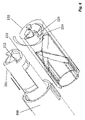
図1は、全体として、例示的な薬物送達デバイスを示しており、この薬剤送達デバイスは、加圧ガスを使用して一用量の薬剤を送達する。特に、図1は、注射前の初期状態にある薬物送達デバイス100を示す。さらに、図2は、注射前の初期状態にある薬物送達デバイス100の構成部材の分解図を示す。
FIG. 1 generally illustrates an exemplary drug delivery device that uses pressurized gas to deliver a dose of drug. In particular, FIG. 1 shows
図1及び図2に示されるように、薬物送達デバイス100は、主筐体110及び主筐体110内に配設された注射器120を有する。主筐体110は、第1筐体部分111及び第2筐体部分112を有する。第1及び第2筐体部分111、112は、2つの筐体部分111、112間の係合を提供するための対応する係合機構を有する。例示的な実施形態において、薬物送達デバイス100の組立中において、第1及び第2筐体部分111、112は、互いに不可逆的に取り付けられる。しかしながら、他の実施形態において、筐体部分111、112は、同様に、互いに対して可逆的に取り付けられ得る。主筐体110を第1及び第2筐体部分111、112を備えるように示しているが、他の例において、主筐体110は、より多くのまたはより少ない部分を備え得る。例えば、例示的な実施形態において、主筐体110は、一体的な構成であり得る。図2を参照すると、注射器120は、薬剤を保持する注射器本体121と、針122と、針122を覆う第1及び第2針カバー123、124と、を有する。ピストンまたはストッパ(図示略)は、注射器本体121内に配設されている。残りの構成部材は、以下でさらに詳述する空圧式動力パック130の一部である。追加でまたはあるいは、注射器本体121内のピストン/ストッパ及びプランジャ150は、注射を完了すると主本体窓113(図1参照)から視認可能であり得る。このような例において、送達の終了は、ピストン及びプランジャ150が移動を停止していることによって示され得る。他の用量送達を完了したことを示すものは、同様に可能である。
As shown in FIGS. 1 and 2, the
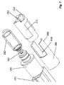
図3及び図4を参照すると、薬物送達デバイス100は、注射器120から針122を通して薬剤を吐出させるための空圧式動力パック130をさらに有する。空圧式動力パック130は、針シールド140と、プランジャ150と、プランジャストッパ152と、第1回転体160と、プランジャ支持体170と、第1ブラケット180と、オリフィス181と、破断体182と、ワッシャ183と、第2回転体220と、後側キャップ230と、を有する。この例において、第2筐体部分112は、この筐体部分の遠位端部において開口部(図示略)を有し、後側キャップ230は、第2筐体部分112の遠位端部と結合されて開口部を覆う。
Referring to FIGS. 3 and 4,
図3に示すように、針シールド140の遠位端部は、第1回転体160の近位端部と接触している。このため、針シールド140を注射場所に押し付けると、遠位方向の力は、針シールド140から第1回転体160に伝達され得る。この結果、針シールド140及び第1回転体160は、遠位方向で一緒に移動する。第1バネ141(図2に示す)は、第1筐体部分111の内面と針シールド140の内面との間に配置されている。第1筐体部分111は、移動不能なままとされ、針シールド140は、薬物送達デバイス100の軸に沿って長手方向で移動可能である。このため、注射場所に当接して押し付けると、遠位方向で移動している針シールド140は、第1バネ141を圧縮する。このため、ユーザが薬物送達デバイス100を注射場所から取り外すと、その後、第1バネ141は、拡張して近位方向で針シールド140を移動させる。他方、第2バネ200は、第1回転体160の遠位端部と後側キャップ230の内面との間に配置されている。第2バネ200は、針シールド140から第1回転体160にかかる力の少なくとも一部を吸収するために使用されている。このため、第1バネ141及び第2バネ200は、協働し、落下または輸送のようなランダムな事象中に形成された力が針シールド140及び第1回転体160双方を遠位方向で押して空圧式動力パックを偶発的に作動させるのに十分なほど強くないようにすることを保証する。
As shown in FIG. 3, the distal end of
図4に示すように、ガス源保持体211は、管状形状を有しており、ガス源保持体の内部空間は、ガス源210を収容するために使用されている。この例において、ガス源210は、加圧ガスを格納してシール(図示略)を有する金属製容器であり、シールにある破断した開口部を通して加圧ガスを解放するために破断される。そして、ガス源保持体211は、管状第2回転体220の内部空間内に配置されている。ガス源保持体211は、図7に示すように、第1ブラケット180と連結されるものである。第1ブラケット180は、第1ブラケット180の遠位端部から延在する一対の腕体400を有しており、一対の切欠部410は、これら腕体400間に形成されている。他方、ガス源保持体211の近位端部の一部は、腕体400を収容するために切り開かれている。同様に、上記切り開き部分の隣にあるガス源保持体211の突起は、切欠部410内に嵌合され得る。第1ブラケット180とガス源保持体211との間のこの構成により、ガス源保持体211が薬物送達デバイス100の軸に対してほぼ長手方向でのみ移動し得ることを保証する。第1ブラケット180とガス源保持体211との間の相互作用を以下でさらに説明する。
As shown in FIG. 4 , the
加圧ガス源210は、プランジャ150を前方に推進させて注射器120内の薬剤を吐出させるのに適した任意の加圧ガス源であり得る。例示的な実施形態において、加圧ガスは、CO2、アルゴンまたは窒素である。他の例の加圧ガスも同様に可能である。さらに、例示的な実施形態において、加圧ガス源210は、50PSIから3000PSIの間の圧力まで加圧されたガスを収容する。しかしながら、他の例において、圧力は、600PSI未満または3000PSIより大きくてもよい。例えば、別の例において、圧力は、500PSIから600PSIである。さらに別の例において、圧力は、3000PSIから3500PSIである。他の例の圧力も同様に可能である。
この例において、破断体182は、第2ブラケット190の首部内にある内部空間内に固定されている。ワッシャ183は、第1ブラケット180の内部空間内に配置され、ガス源210の首部を囲むために使用されており、ガス源210と気密係合を保証する。本明細書で使用されるように、「気密係合」は、用量送達処理中にシールを通してガスが漏洩することを防止するまたはほぼ防止するシールを提供する係合を意味する。用語「ほぼ」によって、これは、記載した特徴、パラメータまたは値が正確に達成される必要がなく、許容誤差、測定エラー、測定精度限界及び当業者に公知の他の要因を含む逸脱または変更が特性が提供しようとしている効果を排除しない量で生じ得ること、を意味する。同様に、第2ブラケット190の遠位側にある首部は、第1ブラケット180の近位部分と連結するように構成されている。
In this example, the breaking
オリフィス181は、プランジャ支持体170の遠位部分にある内部空間内に配置されており、プランジャ支持体170との気密係合を保証するように構成されている。図9を参照。オリフィス181は、オリフィスの反対側にある近位及び遠位端部に各別にある2つの開口部を有しており、それにより、破断体182からの加圧ガスは、遠位端部にある開口部を通過し、オリフィスの近位端部にある開口部を通してオリフィス181から出得る。
プランジャストッパ152とプランジャ150の少なくとも一部とは、プランジャ支持体170内に配置されている。図9参照。プランジャストッパ152は、プランジャ150の遠位部分と連結されており、それにより、これらプランジャストッパ及びプランジャは、長手方向に沿って共に移動可能である。オリフィス181から出る加圧ガスは、プランジャストッパ152及びプランジャ152双方を押し、近位方向で移動させる。プランジャストッパ152は、同様に、プランジャ支持体170の少なくとも首部分の内面との気密係合を保証し、プランジャストッパ152を押す加圧ガスの漏洩を最小化する。
上記は、構成部材の概要及び構成部材間の相互作用である。以下、これら相互作用を図面を用いて詳述する。 The above is an overview of the components and interactions between the components. These interactions will be described in detail below with reference to the drawings.
ここで、針シールド140、第1回転体160及び第2回転体220間の相互作用を説明するために、図3及び図5を参照する。空圧式動力パック130を作動させる第1ステップは、針シールド140の近位端部を注射場所に押し付けることである。針シールド140は、第1筐体部分111内を長手方向で移動可能である。このため、注射場所からの反力は、針シールド140を押して遠位方向で移動させる。針シールド140が遠位方向で移動するにしたがって、針シールドの遠位端部は、第1回転体160の近位端部と接触し、同様に、第1回転体160を押して同様に遠位方向で移動させる。図3及び図5に示すように、第1回転体160は、第1回転体160の遠位端部の2つの両側部に配設された2対の第1突起161を有する。第1突起161は、第2筐体部分112の内面に配設された溝部(図示略)と連結するように構成されている。第1突起161及び対応する溝部は、長手方向に沿って延在しており、薬物送達デバイス100の軸と平行である。これにより、第1回転体160は、針シールド140からの遠位方向の力によって回転されることが防止される。すなわち、針シールド140及び第1回転体160は、薬物送達デバイス100の軸に関して長手方向で移動するように構成されている。
3 and 5 to describe the interaction between the
図5は、第1及び第2回転体160、220の斜視図を示す。図5に示すように、第1回転体160は、第1回転体160の遠位端部の内面に配設された一対の第2突起162さらに有する。他方、第2回転体220の一部は、切り開かれており、溝部221を形成し、第2突起162を収容する。溝部221は、薬物送達デバイス100の軸に対して斜めになっており、第1回転体160の長手方向での移動中に第2突起162と接触するように構成された傾斜壁部222を有する。上述のように、遠位方向での針シールド140の移動は、同様に、第1回転体160を遠位方向で移動させる。同様に、第1回転体160の第1突起161と第2筐体部分112の内面との間の結合は、第1回転体160を長手方向でのみ移動させる。このため、第1回転体160が遠位方向で移動するにしたがって、第1回転体の第2突起162は、傾斜壁部222と衝突し、第2回転体220を図5において矢印で示すように反時計回り方向で回転させる。
FIG. 5 shows a perspective view of the first and second rotating bodies 160,220. As shown in FIG. 5, the first
図6は、第1回転体160、第2回転体220、ガス源保持体211及び第1ブラケット180を示す斜視図であり、第2回転体220は、第2回転体の内部構造を示すために透明にされている。図示のように、第2回転体220は、第2回転体の内面から延在する一対の第3突起223を有する。第3突起223それぞれは、第2回転体220を回転させる前にガス源保持体211と連結するように構成された固定部材224を有する。ガス源保持体211は、第1回転体160によって回転される前に第2回転体220と連結するために、固定部材224を収容するように構成されている。ガス源保持体211は、同様に、第3突起223に対応する一対の傾斜勾配部213を有する。第2回転体220を回転させる前に、第3突起223は、傾斜勾配部213に単に載置されており、一方で、固定部材224は、間隙212内に嵌合されている。しかしながら、第1回転体160が第2回転体220を反時計回り方向で回転させるにしたがって、固定部材224は、間隙212から連結解除する。同様に、第3突起223は、傾斜勾配部213との衝突を開始し、この処理中に、ガス源保持体211全体を押して近位方向で移動させる。
FIG. 6 is a perspective view showing the first
上述のように、第1回転体160の切欠部410(図7に示す)は、第2回転体220の移動をほぼ長手方向に沿うように制限する。さらに、ガス源210は、ガス源保持体211内に配置されており、これら2つの構成部材は、同じ方向で共に移動する。したがって、第1回転体160の移動及び第2回転体220の移動は、結果として、近位方向で第2ブラケット190内で破断体182に向かうガス源210及びガス源保持体211の移動を引き起こす。図7が示すように、その後、破断体182は、ガス源210のシールを穿刺し、内部の加圧ガスを解放する。そして、加圧ガスは、管状破断体182の先鋭端部を通過し、反対側の端部にある開口部を通って出る。
As mentioned above, the notch 410 (shown in FIG. 7) of the
図8は、ガス源210並びに第2ブラケット190内のオリフィス181及び破断体182を示す斜視図であり、第2ブラケット190は、第2ブラケットの内部構造を示すことを容易にするために透明にされている。破断体182は、第2ブラケット190の首部分191内に固定されており、首部分191との気密係合を保証する。他方において、オリフィス181は、第2ブラケット190の主部分192内に固定されており、同様に、主部分192との気密係合を保証する。図4、図8及び図9に示すように、オリフィス181は、2つの開口部を有しており、遠位端部にある一方の開口部は、破断体182から出た加圧ガスを受け、近位端部にある他方の開口部は、加圧ガスをオリフィス181から出すためのものである。開口部の寸法は、オリフィス181から出る間に発生するガスの圧力を調整するように調節され得る。この例において、オリフィス181の近位端部にある開口部は、遠位端部にある開口部よりも小さいが、これに限定されない。他の例において、オリフィス181の開口部は、プランジャ150を押す必要性に基づいてガスが形成する圧力を調整するために調節され得る。同様に、オリフィス181は、加圧ガスがオリフィス181を出てプランジャ150が押す流量を調整する。本実施形態において、オリフィス181は、流量をほぼ一定に維持するように構成されており、加圧ガスからの一定の力がプランジャ150を押すことを保証する。他の実施形態において、オリフィス181は、異なる力出力プロファイルを形成するために、変化した流量を生成するように構成され得る。
FIG. 8 is a perspective view showing
図9は、ガス源210、ワッシャ183、破断体182、オリフィス181、第2ブラケット190、プランジャ支持体151及びプランジャ150を示す斜視図であり、プランジャ支持体151及び第2ブラケット190は、これらプランジャ支持体及び第2ブラケットの内部構造を示すことを容易にするために透明にされている。図9において、ガス源210にあるシールは、破断体182によって穿刺されており/破断されており、ガス源210内の加圧ガスを解放する。ガスは、破断体182を通過し、そして、破断体182とプランジャ支持体151の首部分内にあるオリフィス181との間において第2ブラケット190内の空間に入る。オリフィス181の遠位端部にある開口部は、破断体182の開口部を向くように構成されており、それにより、破断体182を出た加圧ガスは、オリフィス181内に入り得る。そして、同じ加圧ガスは、近位端部にある開口部を通してオリフィス181から出て、プランジャストッパ152とオリフィス181との間の空間に入る。その後、加圧ガスは、プランジャ支持体151とプランジャ150との組合体を近位方向で押し続ける。この例において、プランジャ150の一端部は、プランジャストッパ152に連結されている一方、他端部は、注射器120の注射器本体121内にあるピストン/ストッパと接触するように構成されている。このため、加圧ガスがプランジャ150を押して近位方向で移動すると、プランジャ150は、ピストン/ストッパ152と接触し、その後同様に、ピストン/ストッパ152を押して近位方向で移動させる。そして、ピストン/ストッパ152のこの近位方向での移動は、注射器本体121内の薬剤を押し、針122を通過し、最終的に、薬剤送達のために注射場所に入る。
FIG. 9 is a perspective view showing
追加で、注射器120図を図2のこの例示的な実施形態において説明したが、注射器、アンプル、カートリッジ、包囲体など任意の適切なタイプの薬剤容器を開示した薬物送達デバイス100で使用し得る。さらに、薬剤は、医療のために使用される任意の適切な物質であり得る。例示的な実施形態において、薬剤は、(一般にアドレナリンとして公知の)エピネフリンである。
Additionally, although a
例示的な実施形態において、開示した空圧式動力パックは、一定のまたはほぼ一定の力でプランジャを推進させるように構成され得る。一定のまたはほぼ一定の力でプランジャを推進させるように構成された空圧式動力パックを有する例示的な薬物送達デバイスを図1から図9を参照して説明する。 In an exemplary embodiment, the disclosed pneumatic power pack can be configured to propel the plunger with a constant or near constant force. An exemplary drug delivery device having a pneumatic power pack configured to propel a plunger with a constant or near-constant force is described with reference to FIGS. 1-9.
空圧式動力パック130は、任意の適切なほぼ一定の力で注射器120内のプランジャを前方へ推進させ得る。本明細書で述べたように、用語「ほぼ」によって、これは、記載した特徴、パラメータまたは値が正確に達成される必要がなく、許容誤差、測定エラー、測定精度限界及び当業者に公知の他の要因を含む逸脱または変更が特性が提供しようとしている効果を排除しない量で生じ得ること、を意味する。
図10及び図11は、本開示の別の実施形態にかかる薬剤送達デバイスを示す。特に、図10は、注射前の初期状態にある薬物送達デバイス100を示す。さらに、図11は、注射前の初期状態にある薬物送達デバイス100の構成部材の分解図を示す。
Figures 10 and 11 show a drug delivery device according to another embodiment of the present disclosure. In particular, Figure 10 shows the
図10及び図11に示すように、薬物送達デバイス100は、第1筐体部分111、第2筐体部分112及び第3筐体部分114を有する主筐体110を有する。第1及び第2筐体部分111、112は、2つの筐体部分111、112間の係合を提供するための対応する係合機構を有する。同様に、第2及び第3筐体部分112、114は、2つの筐体部分112、114間の係合を提供するための対応する係合機構を有する。例示的な実施形態において、薬物送達デバイス100の組立中に、筐体部分111、112、114は、互いに不可逆的に取り付けられている。しかしながら、他の実施形態において、筐体部分111、112、114は、同様に、互いに可逆的に取り付けられ得る。薬物送達デバイス100は、第1筐体部分111の近位端部を覆うキャップ115を有する。薬物送達デバイス100は、同様に、キャップ115と連結するように構成され空圧式動力パック130が囲む注射器の針を覆う針シールドを取り外すための針シールド取外器を有する。
As shown in FIGS. 10 and 11 ,
薬物送達デバイス100は、同様に、第1実施形態における空圧式動力パックとほぼ同一である空圧式動力パック130を有する。この実施形態における空圧式動力パック130の構成部材は、第1実施形態における空圧式動力パック130の構成部材と機能的に同一である。このため、構成部材及びこれら構成部材の機能を詳細には説明しない。
図12は、薬剤送達デバイスの斜視図を示し、第1筐体部分111は、取り外されており、第2筐体部分112は、図示を容易にするために透明にされている。本実施形態において、第1回転体160は、少なくとも1つの可撓性舌部163を有し、この舌部は、第1回転体160の近位端部に配設され、ロック溝部164を有する。他方、第2筐体部分112は、ロック突起117を有し、このロック突起は、第2筐体部分112の内面に配設されており、ロック溝部164に対応する。薬物送達デバイス100を最終的に組み立てた後、ロック突起117は、ロック溝部164に嵌合して舌部163に係合する。このようにして、舌部163が径方向内側に撓んでロック突起117を係合解除させない限り、ロック突起117は、第1回転体160が遠位方向で移動されることを防止する。舌部163をロック突起117から係合解除させるために、ユーザは、針シールド140を注射場所に対して押し、針シールド140を遠位方向で移動させる必要がある。そして、針シールド140は、舌部163と相互作用し、舌部を径方向内側に撓ませてロック突起117を係合解除させ得る。いったん係合解除を完了すると、その後、針シールド140は、第1回転体160の近位端部に当接し、第2回転体220のその後の回転体のために第1回転体を遠位方向で移動させる。
Figure 12 shows a perspective view of the drug delivery device, with the
図13は、薬物送達デバイス100の遠位端部の横断面図を示す。本実施形態において、薬物送達デバイス100は、第3筐体部分114とガス源保持体211との間に配設された補助素子240を有する。補助素子240は、空圧式動力パック130の破断体(図示略)によってガス源210のシールを破断させるためにガス源保持体211を近位方向で押す必要がある追加の力を提供するように構成されている。本実施形態において、補助素子240は、バネであるが、ガス源保持体211を近位方向で押すための力を提供するように構成された他の公知の素子であり得る。さらに、薬物送達デバイス100は、補助素子240の軸が長手方向でありかつ薬物送達デバイス100の軸と平行であることを保証するために、第3筐体部分114の内面に配設された第1案内素子241と、ガス源保持体211に配設された第2案内素子242と、を有する。
FIG. 13 shows a cross-sectional view of the distal end of
例示的な実施形態において、プランジャを推進させるほぼ一定の力は、10Nから100N±15Nの間の力の範囲にある任意のほぼ一定の力で推進される。さらに、本明細書で使用するように、Xニュートンのほぼ一定の力は、10Nから100N±15Nの間の範囲にある任意の力を意味する。 In an exemplary embodiment, the substantially constant force propelling the plunger is urged with any substantially constant force in the range of forces between 10N and 100N±15N. Further, as used herein, an approximately constant force in X Newtons means any force ranging between 10N and 100N±15N.
有利には、開示した空圧式動力パックは、自動注射デバイス内でプランジャを前方へ推進させるためのコスト効率の高い手段を提供する。さらに、開示した実施形態にかかる空圧式動力パックは、同様に、ほぼ一定の力でプランジャを前方へ推進させるための低コストな手段を提供する。したがって、開示した空圧式動力パックは、自動注射デバイスを製造するコストを低減することを補助し得る。 Advantageously, the disclosed pneumatic power pack provides a cost-effective means for propelling a plunger forward within an automatic injection device. Further, the pneumatic power packs of the disclosed embodiments similarly provide a low cost means for propelling the plunger forward with substantially constant force. Accordingly, the disclosed pneumatic power pack can help reduce the cost of manufacturing automatic injection devices.
図に示す例において、薬物送達デバイス100は、可変ではない用量の薬剤を注射するように構成されている。しかしながら、他の実施形態において、薬物送達デバイスは、ユーザが可変の単一用量を選択することを可能とするように構成され得る。例えば、例示的な実施形態において、ユーザは、2つの異なる用量値、3つの異なる用量値、4つの異なる用量値などを選択できる。
In the illustrated example,
図において、様々な係合機構は、薬物送達デバイスの1以上の構成部材間の係合を提供するために示されている。係合機構は、スナップロック、スナップ嵌合、形状嵌合、バヨネット、ルアーロック、ネジまたはこれら設計の組合せのような任意の適切な接続機構であり得る。他の設計も同様に可能である。 In the figures various engagement mechanisms are shown for providing engagement between one or more components of the drug delivery device. The engagement mechanism may be any suitable connection mechanism such as snap lock, snap fit, form fit, bayonet, luer lock, screw or combination of these designs. Other designs are possible as well.
理解すべきことは、図示した構成部材が例のみを意図していること、である。他の例示的な実施形態において、より少ない構成部材、追加の構成部材及び/または代替の構成部材も同様に可能である。さらに、理解すべきことは、本開示の上述して示した実施形態が、非限定的な例とされていること、及び、これら実施形態を特許請求の範囲内で改変し得ること、である。 It should be understood that the illustrated components are intended as examples only. In other exemplary embodiments, fewer components, additional components and/or alternative components are possible as well. Furthermore, it is to be understood that the above-described illustrated embodiments of the present disclosure are intended as non-limiting examples, and that these embodiments may be modified within the scope of the claims. .
様々な態様及び実施形態を本明細書で開示したが、他の態様及び実施形態は、当業者に明らかである。本明細書で開示した様々な態様及び実施形態は、例示目的でありかつ限定することを意図しておらず、真の範囲は、以下の特許請求の範囲に資格を付与する均等物の全範囲と共に、このような特許請求の範囲が示す。同様に理解することは、本明細書で使用した専門用語が特有の実施形態のみを説明する目的であり、限定することを意図していないこと、である。 While various aspects and embodiments have been disclosed herein, other aspects and embodiments will be apparent to those skilled in the art. The various aspects and embodiments disclosed herein are for purposes of illustration and are not intended to be limiting, the true scope being the full range of equivalents to which the following claims are entitled Together, such claims point out. It is also to be understood that the terminology used herein is for the purpose of describing particular embodiments only and is not intended to be limiting.
100 薬物送達デバイス、110 主筐体、121 注射器本体(薬剤容器)、123 第1針カバー、124 第2針カバー、130 空圧式動力パック、150 プランジャ、152 プランジャストッパ、160 第1回転体、162 第2突起(第1部材)、180 第1ブラケット、182 管状破断体、190 第2ブラケット、210 加圧ガス源、211 ガス源保持体、212 間隙(第2固定部材)、213 傾斜勾配部(第4部材)、220 管状第2回転体、222 傾斜壁部(第2部材)、223 第3突起(第3部材)、224 固定部材(第1固定部材)
100
Claims (12)
加圧ガスを格納する加圧ガス容器と、
前記加圧ガス容器から加圧ガスを解放させるための起動組立体と、
を備え、
前記起動組立体が、
先鋭端部を有する破断体と、
起動体と、
前記起動体及び前記加圧ガス容器と連結された回転体と、
を有し、
前記起動体が、第1位置から第2位置に向けて移動するように構成され、当該空圧式動力パックの軸回りにおける前記回転体の回転を引き起こし、そして、前記回転体が前記加圧ガス容器を前記破断体の前記先鋭端部に向けて駆動して加圧ガスを解放させることを特徴とする空圧式動力パック。 A pneumatic power pack for use in a drug delivery device, comprising:
a pressurized gas container for storing pressurized gas;
an activation assembly for releasing pressurized gas from the pressurized gas container ;
with
the activation assembly comprising:
a fractured body having a sharp edge;
an activation body;
a rotating body connected to the activating body and the pressurized gas container;
has
The actuating body is configured to move from a first position toward a second position to cause rotation of the rotating body about the axis of the pneumatic power pack , and the rotating body moves the pressurized gas container . towards said sharp end of said breaking body to release pressurized gas.
前記加圧ガス容器が、前記保持体内に配設されており、
前記起動体の軸方向移動が、前記回転体の回転を引き起こし、そして、前記保持体及び前記加圧ガス容器を前記破断体の前記先鋭端部に向けて駆動することを特徴とする請求項1に記載の空圧式動力パック。 the actuation assembly further comprising a retainer coupled to the rotating body;
The pressurized gas container is arranged in the holding body,
2. Axial movement of said actuating body causes rotation of said rotating body and drives said holding body and said pressurized gas container towards said sharp end of said breaking body. pneumatic power pack as described in .
前記第1ブラケットと前記保持体との間の連結により、前記回転体の回転によって前記保持体が軸方向に移動することを特徴とする請求項2に記載の空圧式動力パック。 the activation assembly further comprising a first bracket coupled with the retainer;
3. The pneumatic power pack of claim 2, wherein the connection between said first bracket and said retainer causes axial movement of said retainer upon rotation of said rotating body .
加圧ガスの流動が、前記加圧ガス容器から前記破断体を通って進行し、前記経路から出ることを特徴とする請求項3に記載の空圧式動力パック。 said first bracket having a path for receiving at least a portion of said fractured body and said pressurized gas container ;
4. The pneumatic power pack of claim 3, wherein the flow of pressurized gas travels from said pressurized gas container , through said rupture body and out of said path.
前記オリフィスが、前記第1ブラケットの前記経路から出るガスの流動を受けて、当該オリフィスから出る前記ガスの圧力を調整する開口部を有することを特徴とする請求項4に記載の空圧式動力パック。 further comprising a second bracket and an orifice disposed within the second bracket;
5. The pneumatic according to claim 4, wherein said orifice has an opening for receiving the flow of gas exiting said passage of said first bracket to regulate the pressure of said gas exiting said orifice. power pack.
前記回転体が、前記第1部材に係合するように構成された第2部材を有し、
前記第1部材が、前記起動体の前記第1位置から前記第2位置への軸方向移動中に相互作用して前記回転体を回転させるように構成されていることを特徴とする請求項1に記載の空圧式動力パック。 the activator having a first member;
said rotating body having a second member configured to engage said first member;
2. The first member is configured to interact to rotate the rotating body during axial movement of the actuator from the first position to the second position. pneumatic power pack as described in .
前記第2部材が、前記回転体の外面に配設されていることを特徴とする請求項6に記載の空圧式動力パック。 wherein the first member is disposed on an inner surface of the activator;
7. A pneumatic power pack according to claim 6, wherein said second member is disposed on the outer surface of said rotor.
前記第2部材が、前記回転体の内面に配設されていることを特徴とする請求項6に記載の空圧式動力パック。 wherein the first member is disposed on the outer surface of the activator;
7. A pneumatic power pack according to claim 6, wherein said second member is disposed on the inner surface of said rotor.
前記保持体が、前記第3部材に係合するように構成された第4部材を有し、
前記第3部材が、前記回転体の回転中に前記第4部材と相互作用して前記加圧ガス容器を駆動させるように構成されていることを特徴とする請求項2に記載の空圧式動力パック。 The rotating body has a third member,
said retainer having a fourth member configured to engage said third member;
3. The pneumatic power of claim 2 , wherein said third member is configured to interact with said fourth member during rotation of said rotating body to drive said pressurized gas container . pack.
前記保持体が、前記起動体によって回転されて前記第1位置から第2位置へ移動する前に前記第1固定部材に係合して前記回転体の位置を維持するように構成された第2固定部材を有することを特徴とする請求項9に記載の空圧式動力パック。 The rotating body has a first fixed member,
a second position configured to engage the first fixing member to maintain the position of the rotating body before the holding body is rotated by the actuating body to move from the first position to the second position; 10. A pneumatic power pack according to claim 9, comprising a fixed member.
前記主筐体に対して軸方向に移動可能に構成された針カバーと、
前記針カバー内に配設されてストッパ及び薬剤を有する薬剤容器と、
請求項1から10のいずれか1項に記載の空圧式動力パックと、
を備え、
前記針カバーが、前記空圧式動力パックの前記起動体と相互作用するように構成され、
前記針カバーの軸方向移動により、前記起動体を前記第1位置から前記第2位置へ移動させ、
前記空圧式動力パックが、前記ストッパに係合して加圧ガスによって近位方向で移動可能であるように構成されたプランジャをさらに有することを特徴とする薬物送達デバイス。 a main housing;
a needle cover configured to be axially movable with respect to the main housing;
a medicament container disposed within the needle cover and having a stopper and a medicament;
A pneumatic power pack according to any one of claims 1 to 10;
with
said needle cover configured to interact with said actuator of said pneumatic power pack;
axial movement of the needle cover moves the actuator from the first position to the second position;
A drug delivery device, wherein the pneumatic power pack further comprises a plunger configured to engage the stopper and be movable proximally by pressurized gas.
前記主筐体内に配設されかつストッパ及び薬剤を有する薬剤容器と、
駆動パックと、
を備え、
前記駆動パックが、空圧式動力パックであり、
加圧ガスを格納する加圧ガス容器と、
前記加圧ガス容器から加圧ガスを解放するための起動組立体と、を備え、
前記起動組立体が、
先鋭端部を有する破断体と、
起動体と、
前記起動体及び前記加圧ガス容器と連結された回転体と、
を有し、
前記起動体が、第1位置から第2位置へ移動可能であり、当該空圧式動力パックの軸回りにおける前記回転体の回転を引き起こし、それにより、前記回転体が前記加圧ガス容器を前記破断体の前記先鋭端部に向けて駆動して加圧ガスを解放させることを特徴とする薬物送達デバイス。 a main housing;
a medicament container disposed within the main housing and having a stopper and a medicament;
a drive pack;
with
the drive pack is a pneumatic power pack;
a pressurized gas container for storing pressurized gas;
an activation assembly for releasing pressurized gas from the pressurized gas container ;
the activation assembly comprising:
a fractured body having a sharp edge;
an activation body;
a rotating body connected to the activating body and the pressurized gas container;
has
The actuator is movable from a first position to a second position to cause rotation of the rotating body about the axis of the pneumatic power pack , whereby the rotating body ruptures the pressurized gas container . A drug delivery device characterized by being driven toward said sharp end of the body to release pressurized gas.
Applications Claiming Priority (5)
| Application Number | Priority Date | Filing Date | Title |
|---|---|---|---|
| US201862735047P | 2018-09-22 | 2018-09-22 | |
| US62/735,047 | 2018-09-22 | ||
| EP18205275 | 2018-11-08 | ||
| EP18205275.3 | 2018-11-08 | ||
| PCT/EP2019/074299 WO2020058068A1 (en) | 2018-09-22 | 2019-09-12 | Pneumatic power pack |
Publications (2)
| Publication Number | Publication Date |
|---|---|
| JP2021525153A JP2021525153A (en) | 2021-09-24 |
| JP7140850B2 true JP7140850B2 (en) | 2022-09-21 |
Family
ID=67875476
Family Applications (1)
| Application Number | Title | Priority Date | Filing Date |
|---|---|---|---|
| JP2020567480A Active JP7140850B2 (en) | 2018-09-22 | 2019-09-12 | pneumatic power pack |
Country Status (6)
| Country | Link |
|---|---|
| US (1) | US11951287B2 (en) |
| EP (1) | EP3852839A1 (en) |
| JP (1) | JP7140850B2 (en) |
| KR (1) | KR102507797B1 (en) |
| CN (1) | CN112312944B (en) |
| WO (1) | WO2020058068A1 (en) |
Families Citing this family (2)
| Publication number | Priority date | Publication date | Assignee | Title |
|---|---|---|---|---|
| USD952835S1 (en) * | 2020-07-15 | 2022-05-24 | Novo Nordisk A/S | Injector pen |
| WO2023064313A2 (en) * | 2021-10-11 | 2023-04-20 | Congruence Medical Solutions, Llc | Autoinjection device |
Citations (4)
| Publication number | Priority date | Publication date | Assignee | Title |
|---|---|---|---|---|
| WO2013086612A1 (en) | 2011-12-15 | 2013-06-20 | Socpra Sciences Et Genie S.E.C. | Mechanism for puncturing a gas cartridge |
| JP2017519580A (en) | 2014-06-27 | 2017-07-20 | ノボ・ノルデイスク・エー/エス | Injection device with needle shield restraint |
| US20180008775A1 (en) | 2016-07-07 | 2018-01-11 | Carebay Europe Ltd. | Drug Delivery Device with Pneumatic Power Pack |
| WO2018011255A1 (en) | 2016-07-14 | 2018-01-18 | Sanofi-Aventis Deutschland Gmbh | Drug delivery device |
Family Cites Families (9)
| Publication number | Priority date | Publication date | Assignee | Title |
|---|---|---|---|---|
| US2605763A (en) * | 1948-01-31 | 1952-08-05 | Becton Dickinson Co | Injection device |
| US3688765A (en) * | 1969-10-03 | 1972-09-05 | Jack S Gasaway | Hypodermic injection device |
| US4790824A (en) * | 1987-06-19 | 1988-12-13 | Bioject, Inc. | Non-invasive hypodermic injection device |
| US5312335A (en) | 1989-11-09 | 1994-05-17 | Bioject Inc. | Needleless hypodermic injection device |
| GB2410188B (en) * | 2004-01-23 | 2006-01-25 | Medical House Plc | Injection device |
| US7717874B2 (en) * | 2004-05-28 | 2010-05-18 | Bioject, Inc. | Needle-free injection system |
| WO2010123439A1 (en) * | 2009-04-24 | 2010-10-28 | Shl Group Ab | Medicament delivery device |
| GB201210082D0 (en) | 2012-06-07 | 2012-07-25 | Consort Medical Plc | Improved syringe |
| CN107847668A (en) * | 2015-06-15 | 2018-03-27 | 纽昂斯设计康涅狄格有限责任公司 | Gas-actuated formula automatic injector with air damper |
-
2019
- 2019-09-12 US US16/972,504 patent/US11951287B2/en active Active
- 2019-09-12 EP EP19765493.2A patent/EP3852839A1/en active Pending
- 2019-09-12 CN CN201980040440.0A patent/CN112312944B/en active Active
- 2019-09-12 KR KR1020207036450A patent/KR102507797B1/en active IP Right Grant
- 2019-09-12 WO PCT/EP2019/074299 patent/WO2020058068A1/en active Application Filing
- 2019-09-12 JP JP2020567480A patent/JP7140850B2/en active Active
Patent Citations (4)
| Publication number | Priority date | Publication date | Assignee | Title |
|---|---|---|---|---|
| WO2013086612A1 (en) | 2011-12-15 | 2013-06-20 | Socpra Sciences Et Genie S.E.C. | Mechanism for puncturing a gas cartridge |
| JP2017519580A (en) | 2014-06-27 | 2017-07-20 | ノボ・ノルデイスク・エー/エス | Injection device with needle shield restraint |
| US20180008775A1 (en) | 2016-07-07 | 2018-01-11 | Carebay Europe Ltd. | Drug Delivery Device with Pneumatic Power Pack |
| WO2018011255A1 (en) | 2016-07-14 | 2018-01-18 | Sanofi-Aventis Deutschland Gmbh | Drug delivery device |
Also Published As
| Publication number | Publication date |
|---|---|
| CN112312944B (en) | 2023-03-21 |
| CN112312944A (en) | 2021-02-02 |
| EP3852839A1 (en) | 2021-07-28 |
| WO2020058068A1 (en) | 2020-03-26 |
| US20210268193A1 (en) | 2021-09-02 |
| JP2021525153A (en) | 2021-09-24 |
| KR102507797B1 (en) | 2023-03-09 |
| US11951287B2 (en) | 2024-04-09 |
| KR20210010929A (en) | 2021-01-28 |
Similar Documents
| Publication | Publication Date | Title |
|---|---|---|
| US20220233776A1 (en) | Automatic drug delivery devices | |
| CN109966594B (en) | Drug delivery device | |
| TWI558430B (en) | Medicament delivery device | |
| CN102946926B (en) | Medicament delivery device | |
| CN107921208B (en) | Removable activation cap for use with an auto-injector assembly | |
| US20180200446A1 (en) | Automatic injection device | |
| EP3481464B1 (en) | Drug delivery device with pneumatic power pack | |
| US10881797B2 (en) | Drive mechanism for an autoinjector | |
| JP7140850B2 (en) | pneumatic power pack | |
| EP3423131B1 (en) | Automatic delivery device with end of injection indication device | |
| US20230372622A1 (en) | Dual-chamber delivery device | |
| JP6005813B2 (en) | Injection device with automatic material combination function |
Legal Events
| Date | Code | Title | Description |
|---|---|---|---|
| A621 | Written request for application examination |
Free format text: JAPANESE INTERMEDIATE CODE: A621 Effective date: 20201203 |
|
| A977 | Report on retrieval |
Free format text: JAPANESE INTERMEDIATE CODE: A971007 Effective date: 20211220 |
|
| A131 | Notification of reasons for refusal |
Free format text: JAPANESE INTERMEDIATE CODE: A131 Effective date: 20211224 |
|
| A521 | Request for written amendment filed |
Free format text: JAPANESE INTERMEDIATE CODE: A523 Effective date: 20220318 |
|
| TRDD | Decision of grant or rejection written | ||
| A01 | Written decision to grant a patent or to grant a registration (utility model) |
Free format text: JAPANESE INTERMEDIATE CODE: A01 Effective date: 20220815 |
|
| A61 | First payment of annual fees (during grant procedure) |
Free format text: JAPANESE INTERMEDIATE CODE: A61 Effective date: 20220908 |
|
| R150 | Certificate of patent or registration of utility model |
Ref document number: 7140850 Country of ref document: JP Free format text: JAPANESE INTERMEDIATE CODE: R150 |