CN113562609B - Hoisting equipment for offshore wind turbine power generation - Google Patents

Hoisting equipment for offshore wind turbine power generation Download PDF

Info

Publication number
CN113562609B
CN113562609B CN202111143555.8A CN202111143555A CN113562609B CN 113562609 B CN113562609 B CN 113562609B CN 202111143555 A CN202111143555 A CN 202111143555A CN 113562609 B CN113562609 B CN 113562609B
Authority
CN
China
Prior art keywords
wall
hollow sleeve
hoisting
guide block
fixedly connected
Prior art date
Legal status (The legal status is an assumption and is not a legal conclusion. Google has not performed a legal analysis and makes no representation as to the accuracy of the status listed.)
Active
Application number
CN202111143555.8A
Other languages
Chinese (zh)
Other versions
CN113562609A (en
Inventor
黄晓炜
李文轩
Current Assignee (The listed assignees may be inaccurate. Google has not performed a legal analysis and makes no representation or warranty as to the accuracy of the list.)
Jiangsu Daoda Wind Power Equipment Technology Co ltd
CCCC First Harbour Consultants Co Ltd
Original Assignee
Jiangsu Daoda Wind Power Equipment Technology Co ltd
Priority date (The priority date is an assumption and is not a legal conclusion. Google has not performed a legal analysis and makes no representation as to the accuracy of the date listed.)
Filing date
Publication date
Application filed by Jiangsu Daoda Wind Power Equipment Technology Co ltd filed Critical Jiangsu Daoda Wind Power Equipment Technology Co ltd
Priority to CN202111143555.8A priority Critical patent/CN113562609B/en
Publication of CN113562609A publication Critical patent/CN113562609A/en
Application granted granted Critical
Publication of CN113562609B publication Critical patent/CN113562609B/en
Active legal-status Critical Current
Anticipated expiration legal-status Critical

Links

Images

Classifications

    • BPERFORMING OPERATIONS; TRANSPORTING
    • B66HOISTING; LIFTING; HAULING
    • B66CCRANES; LOAD-ENGAGING ELEMENTS OR DEVICES FOR CRANES, CAPSTANS, WINCHES, OR TACKLES
    • B66C1/00Load-engaging elements or devices attached to lifting or lowering gear of cranes or adapted for connection therewith for transmitting lifting forces to articles or groups of articles
    • B66C1/10Load-engaging elements or devices attached to lifting or lowering gear of cranes or adapted for connection therewith for transmitting lifting forces to articles or groups of articles by mechanical means
    • B66C1/42Gripping members engaging only the external or internal surfaces of the articles
    • B66C1/44Gripping members engaging only the external or internal surfaces of the articles and applying frictional forces
    • B66C1/445Gripping members engaging only the external or internal surfaces of the articles and applying frictional forces motor actuated
    • BPERFORMING OPERATIONS; TRANSPORTING
    • B66HOISTING; LIFTING; HAULING
    • B66CCRANES; LOAD-ENGAGING ELEMENTS OR DEVICES FOR CRANES, CAPSTANS, WINCHES, OR TACKLES
    • B66C1/00Load-engaging elements or devices attached to lifting or lowering gear of cranes or adapted for connection therewith for transmitting lifting forces to articles or groups of articles
    • B66C1/10Load-engaging elements or devices attached to lifting or lowering gear of cranes or adapted for connection therewith for transmitting lifting forces to articles or groups of articles by mechanical means
    • B66C1/108Load-engaging elements or devices attached to lifting or lowering gear of cranes or adapted for connection therewith for transmitting lifting forces to articles or groups of articles by mechanical means for lifting parts of wind turbines
    • BPERFORMING OPERATIONS; TRANSPORTING
    • B66HOISTING; LIFTING; HAULING
    • B66CCRANES; LOAD-ENGAGING ELEMENTS OR DEVICES FOR CRANES, CAPSTANS, WINCHES, OR TACKLES
    • B66C13/00Other constructional features or details
    • B66C13/04Auxiliary devices for controlling movements of suspended loads, or preventing cable slack
    • B66C13/08Auxiliary devices for controlling movements of suspended loads, or preventing cable slack for depositing loads in desired attitudes or positions
    • B66C13/085Auxiliary devices for controlling movements of suspended loads, or preventing cable slack for depositing loads in desired attitudes or positions electrical
    • FMECHANICAL ENGINEERING; LIGHTING; HEATING; WEAPONS; BLASTING
    • F03MACHINES OR ENGINES FOR LIQUIDS; WIND, SPRING, OR WEIGHT MOTORS; PRODUCING MECHANICAL POWER OR A REACTIVE PROPULSIVE THRUST, NOT OTHERWISE PROVIDED FOR
    • F03DWIND MOTORS
    • F03D1/00Wind motors with rotation axis substantially parallel to the air flow entering the rotor 
    • F03D1/06Rotors
    • F03D1/065Rotors characterised by their construction elements
    • F03D1/0675Rotors characterised by their construction elements of the blades
    • FMECHANICAL ENGINEERING; LIGHTING; HEATING; WEAPONS; BLASTING
    • F03MACHINES OR ENGINES FOR LIQUIDS; WIND, SPRING, OR WEIGHT MOTORS; PRODUCING MECHANICAL POWER OR A REACTIVE PROPULSIVE THRUST, NOT OTHERWISE PROVIDED FOR
    • F03DWIND MOTORS
    • F03D13/00Assembly, mounting or commissioning of wind motors; Arrangements specially adapted for transporting wind motor components
    • F03D13/10Assembly of wind motors; Arrangements for erecting wind motors
    • FMECHANICAL ENGINEERING; LIGHTING; HEATING; WEAPONS; BLASTING
    • F03MACHINES OR ENGINES FOR LIQUIDS; WIND, SPRING, OR WEIGHT MOTORS; PRODUCING MECHANICAL POWER OR A REACTIVE PROPULSIVE THRUST, NOT OTHERWISE PROVIDED FOR
    • F03DWIND MOTORS
    • F03D13/00Assembly, mounting or commissioning of wind motors; Arrangements specially adapted for transporting wind motor components
    • F03D13/20Arrangements for mounting or supporting wind motors; Masts or towers for wind motors
    • F03D13/25Arrangements for mounting or supporting wind motors; Masts or towers for wind motors specially adapted for offshore installation
    • YGENERAL TAGGING OF NEW TECHNOLOGICAL DEVELOPMENTS; GENERAL TAGGING OF CROSS-SECTIONAL TECHNOLOGIES SPANNING OVER SEVERAL SECTIONS OF THE IPC; TECHNICAL SUBJECTS COVERED BY FORMER USPC CROSS-REFERENCE ART COLLECTIONS [XRACs] AND DIGESTS
    • Y02TECHNOLOGIES OR APPLICATIONS FOR MITIGATION OR ADAPTATION AGAINST CLIMATE CHANGE
    • Y02EREDUCTION OF GREENHOUSE GAS [GHG] EMISSIONS, RELATED TO ENERGY GENERATION, TRANSMISSION OR DISTRIBUTION
    • Y02E10/00Energy generation through renewable energy sources
    • Y02E10/70Wind energy
    • Y02E10/72Wind turbines with rotation axis in wind direction
    • YGENERAL TAGGING OF NEW TECHNOLOGICAL DEVELOPMENTS; GENERAL TAGGING OF CROSS-SECTIONAL TECHNOLOGIES SPANNING OVER SEVERAL SECTIONS OF THE IPC; TECHNICAL SUBJECTS COVERED BY FORMER USPC CROSS-REFERENCE ART COLLECTIONS [XRACs] AND DIGESTS
    • Y02TECHNOLOGIES OR APPLICATIONS FOR MITIGATION OR ADAPTATION AGAINST CLIMATE CHANGE
    • Y02EREDUCTION OF GREENHOUSE GAS [GHG] EMISSIONS, RELATED TO ENERGY GENERATION, TRANSMISSION OR DISTRIBUTION
    • Y02E10/00Energy generation through renewable energy sources
    • Y02E10/70Wind energy
    • Y02E10/727Offshore wind turbines

Abstract

The invention discloses hoisting equipment for offshore wind turbine power generation, and particularly relates to the field of wind turbine hoisting, which comprises a wind tower cylinder, a fan blade base and a hoisting plate, wherein a clamping mechanism is arranged in the hoisting plate; through opening second driving motor for first guide block slides, and first guide block passes through the second dwang and drives hollow sleeve and remove, and flabellum frame and wind-force flabellum synchronous movement, thereby convenient completion the removal of flabellum frame and wind-force flabellum, and then effectual improvement the convenience of installation flabellum frame and wind-force flabellum and the effectual efficiency of installing wind-force flabellum that has improved.

Description

Hoisting equipment for offshore wind turbine power generation
Technical Field
The invention relates to the technical field of fan hoisting, in particular to hoisting equipment for offshore fan power generation.
Background
A wind power generator: the wind power generator is an electric power device which converts wind energy into mechanical work, and the mechanical work drives a rotor to rotate so as to finally output alternating current. The wind-driven generator generally comprises wind wheels, a generator (including a device), a direction regulator (empennage), a tower, a speed-limiting safety mechanism, an energy storage device and other components. The prior art has the following problems when hoisting the wind power fan blade:
1. in the prior art, when the wind power fan blade is hoisted, the wind power fan blade is mostly hoisted to the surface of a tower barrel equipment bin through a steel rope of a crane, and the stability of the wind power fan blade in the hoisting process is poor due to the lack of clamping of the wind power fan blade;
2. when hoisting wind-force flabellum, when wind-force flabellum was hoisted to tower section of thick bamboo equipment compartment's periphery, mostly dragged the angle that the hawser controlled wind-force flabellum through the manual work, lead to wind-force flabellum's installation comparatively inconvenient from this, and the efficiency of installation is comparatively low, for this reason, we propose a lifting device for offshore wind turbine electricity generation and be used for solving above-mentioned problem.
Disclosure of Invention
The invention aims to provide hoisting equipment for offshore wind turbine power generation, which aims to solve the problems in the background technology.
In order to solve the technical problems, the invention adopts the following technical scheme: the utility model provides a lifting device for offshore wind turbine power generation, includes wind-force tower section of thick bamboo, flabellum frame and hoisting plate, the inside of hoisting plate is equipped with fixture, the surface of hoisting plate is equipped with adjustment mechanism, adjustment mechanism's surface is equipped with tilting mechanism.
Preferably, an equipment bin is fixedly mounted at the upper end of the wind power tower barrel, a mounting groove is formed in one side of the equipment bin, and wind power blades are uniformly distributed and fixedly mounted on the outer wall of the blade base.
Preferably, the upper surface of the hoisting plate is symmetrically and fixedly provided with connecting seats, the surface of each connecting seat is provided with a through hole, the through holes horizontally correspond to each other, and the inner wall of the hoisting plate is symmetrically provided with notches.
Preferably, fixture is including hollow sleeve, the bearing chassis can be dismantled to hollow sleeve's bottom, hollow sleeve's inner wall evenly distributed fixed mounting has the direction telescopic link, the piston end fixedly connected with semicircle grip block of direction telescopic link, hollow sleeve's outer wall symmetry rotates and is connected with first threaded rod, first threaded rod is close to hollow sleeve's one end and semicircle grip block screw thread rotation and connects, the fixed driving motor that is equipped with of hollow sleeve's outer wall symmetry, the one end fixed connection of a driving output of driving motor and first threaded rod.
Preferably, the contact groove has been seted up to hollow sleeve's outer wall evenly distributed, the outer wall of aerogenerator leaf and the inner wall movable contact in contact groove, hollow sleeve's one side evenly distributed screw thread is kept away from on the bearing chassis rotates and is connected with locking bolt, locking bolt and hollow sleeve screw thread rotate the connection, the bearing chassis is close to hollow sleeve's one side fixed mounting and is filled up with first protection, the one side and the flabellum frame movable contact on bearing chassis are kept away from to first protection pad, the inner wall fixed mounting of semicircle grip block has the second to protect and fills up, the outer wall of flabellum frame and the inner wall movable contact that the second protected and fill up, the first fixed block of first driving motor's outer wall fixedly connected with, one side of first fixed block and hollow sleeve's outer wall fixed connection.
Preferably, the adjusting mechanism comprises a second driving motor, a first rotating rod is rotatably connected between the notches, the driving output end of the second driving motor is fixedly connected with one end of the first rotating rod, both ends of the first rotating rod are fixedly provided with a first bevel gear, the inner wall of the hoisting plate is symmetrically provided with first guide grooves, the inner wall of each first guide groove is connected with a first guide block in a sliding way, the inner wall of the first guide groove is rotationally connected with a second threaded rod which is rotationally connected with the hoisting plate, the second threaded rod is in threaded rotary connection with the first guide block, one end of the second threaded rod is fixedly provided with a second bevel gear, the second bevel gear is meshed with the first bevel gear, the opposite sides of the first guide block are rotatably connected with second rotating rods, one end of the second rotating rod, which is far away from the first guide block, is fixedly connected with the outer wall of the hollow sleeve.
Preferably, the outer wall of the second driving motor is fixedly connected with a second fixed block, and one side of the second fixed block is fixedly connected with the outer wall of the hoisting plate.
Preferably, tilting mechanism is including the cylinder, the piston end fixed mounting of cylinder has the pinion rack, drive gear has been cup jointed to the outer wall of second dwang fixedly, pinion rack and drive gear meshing connection, the second guide way has been seted up to the inner wall of hoist and mount board, the inner wall sliding connection of second guide way has the second guide block, one side of second guide block and the outer wall fixed connection of cylinder.
Preferably, one side of the second guide block is fixedly connected with a synchronization rod, and one end of the synchronization rod, which is far away from the second guide block, is fixedly connected with one side of the first guide block.
Compared with the prior art, the invention has the beneficial effects that:
1. the first driving motor is started to enable the first threaded rod to rotate, the first threaded rod enables the two semicircular toothed clamping plates and the first protection pad to move oppositely, the two semicircular toothed clamping plates and the first protection pad move oppositely and simultaneously clamp the fan blade base, so that clamping and fixing of the fan blade base and the wind fan blade are conveniently completed, and further the stability of the fan blade base and the wind fan blade during subsequent lifting operation is effectively improved;
2. the air cylinder is started, so that the toothed plate moves, the toothed plate drives the transmission gear to rotate, the transmission gear drives the second rotating rod to rotate, and the second rotating rod drives the hollow sleeve and the fan blade base to rotate, so that the fan blade base and the wind fan blade can be conveniently turned over, and convenience in subsequent installation of the fan blade base and the wind fan blade is effectively improved;
3. through opening second driving motor for first guide block horizontal slip, first guide block passes through the second dwang and drives hollow sleeve horizontal migration, flabellum frame and wind-powered fan blade synchronous motion in the hollow sleeve, thereby convenient completion the removal of flabellum frame and wind-powered fan blade, and then effectual improvement the convenience of installation flabellum frame and wind-powered fan blade and the effectual efficiency of installing wind-powered fan blade that has improved.
Drawings
In order to more clearly illustrate the embodiments of the present invention or the technical solutions in the prior art, the drawings used in the description of the embodiments or the prior art will be briefly described below, it is obvious that the drawings in the following description are only some embodiments of the present invention, and for those skilled in the art, other drawings can be obtained according to the drawings without creative efforts.
FIG. 1 is a schematic view of a tower and blades of a wind turbine in a separated state.
FIG. 2 is a schematic view of the suspension plate and the fan blade of the present invention.
FIG. 3 is another schematic view of the suspension plate and the blade of the wind turbine of the present invention.
FIG. 4 is a schematic view of the clamping mechanism of the present invention separated from the fan blades.
FIG. 5 is a schematic view of the connection of the lifting plate, the adjusting mechanism and the turnover mechanism of the present invention.
FIG. 6 is an enlarged view of portion A of FIG. 5 according to the present invention.
Fig. 7 is a schematic cross-sectional structure of the hoisting plate of the present invention.
In the figure: 1. a wind tower; 11. an equipment bin; 12. mounting grooves; 13. a fan blade base; 14. a wind power blade; 2. hoisting the plate; 21. a connecting seat; 22. a through hole; 23. a notch; 3. a clamping mechanism; 31. a hollow sleeve; 311. a contact groove; 32. a load-bearing chassis; 321. a first protective pad; 33. locking the bolt; 34. guiding the telescopic rod; 35. a semicircular clamping plate; 36. a second protective pad; 37. a first threaded rod; 38. a first drive motor; 39. a first fixed block; 4. an adjustment mechanism; 41. a second drive motor; 42. a second fixed block; 43. a first rotating lever; 44. a first bevel gear; 45. a first guide groove; 46. a first guide block; 47. a second threaded rod; 48. a second bevel gear; 49. a second rotating lever; 5. a turnover mechanism; 51. a cylinder; 52. a toothed plate; 53. a transmission gear; 54. a second guide groove; 55. a second guide block; 56. a synchronization rod.
Detailed Description
The technical solutions in the embodiments of the present invention will be clearly and completely described below with reference to the drawings in the embodiments of the present invention, and it is obvious that the described embodiments are only a part of the embodiments of the present invention, and not all of the embodiments. All other embodiments, which can be derived by a person skilled in the art from the embodiments given herein without making any creative effort, shall fall within the protection scope of the present invention.
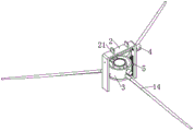
Example (b): as shown in fig. 1-7, the invention provides a hoisting device for offshore wind turbine power generation, which comprises a wind tower cylinder 1, a fan blade base 13 and a hoisting plate 2, wherein the hoisting plate 2 can facilitate the hoisting device to hoist the fan blade base 13, a clamping mechanism 3 is arranged inside the hoisting plate 2, the clamping mechanism 3 can clamp and fix the fan blade base 13, an adjusting mechanism 4 is arranged on the surface of the hoisting plate 2, the adjusting mechanism 4 can adjust the position of the fan blade base 13, a turnover mechanism 5 is arranged on the surface of the adjusting mechanism 4, and the turnover mechanism 5 can conveniently realize turnover of the fan blade base 13.
Further, an equipment bin 11 is fixedly mounted at the upper end of the wind power tower barrel 1, a mounting groove 12 is formed in one side of the equipment bin 11, wind power blades 14 are uniformly distributed and fixedly mounted on the outer wall of the blade base 13, and the blade base 13 can be conveniently mounted inside the mounting groove 12 in one side of the equipment bin 11 by lifting the blade base 13 and the wind power blades 14.
Further, the upper surface symmetry fixed mounting of hoisting plate 2 has connecting seat 21, and through-hole 22 has been seted up on the surface of connecting seat 21, and through-hole 22 level corresponds, and the steel cable of lifting equipment can pass in two through-holes 22 to lifting equipment lifts by crane hoisting plate 2, and notch 23 has been seted up to the inner wall symmetry of hoisting plate 2.
Further, the clamping mechanism 3 comprises a hollow sleeve 31, a bearing chassis 32 can be disassembled at the bottom end of the hollow sleeve 31, the bearing chassis 32 can effectively improve the stability of the fan blade base 13, guide telescopic rods 34 are fixedly distributed on the inner wall of the hollow sleeve 31, a semicircular clamping plate 35 is fixedly connected with the piston end of each guide telescopic rod 34, each guide telescopic rod 34 can enable the semicircular clamping plate 35 to move in the horizontal direction, the semicircular clamping plate 35 can clamp and fix the fan blade base 13, the outer wall of the hollow sleeve 31 is symmetrically and rotatably connected with a first threaded rod 37, one end of each first threaded rod 37, which is close to the hollow sleeve 31, is in threaded connection with the semicircular clamping plate 35, the semicircular clamping plate 35 can be driven to move horizontally while the first threaded rod 37 rotates, a first driving motor 38 is symmetrically and fixedly arranged on the outer wall of the hollow sleeve 31, the driving output end of the first driving motor 38 is fixedly connected with one end of the first threaded rod 37, by turning on the first driving motor 38, the driving shaft of the first driving motor 38 can drive the first threaded rod 37 to rotate.
Further, the outer wall of the hollow sleeve 31 is uniformly distributed with contact grooves 311, the outer wall of the wind power blade 14 is movably contacted with the inner wall of the contact grooves 311, the wind power blade 14 can be conveniently clamped and fixedly installed inside the hollow sleeve 31 by arranging the contact grooves 311, one side of the bearing chassis 32 far away from the hollow sleeve 31 is uniformly distributed with threads and is rotatably connected with a locking bolt 33, the locking bolt 33 is rotatably connected with the hollow sleeve 31 by threads, the fixing and the disassembling of the bearing chassis 32 and the hollow sleeve 31 can be conveniently realized by the knob locking bolt 33, one side of the bearing chassis 32 close to the hollow sleeve 31 is fixedly provided with a first protection pad 321, one side of the first protection pad 321 far away from the bearing chassis 32 is movably contacted with the fan blade base 13, the outer wall of the fan blade base 13 can be prevented from being worn by the first protection pad 321, and the inner wall of the semicircular clamping plate 35 is fixedly provided with a second protection pad 36, the outer wall of flabellum frame 13 and the inner wall movable contact of second protection pad 36, the outer wall that flabellum frame 13 can be avoided to second protection pad 36 receives wearing and tearing, the first fixed block 39 of outer wall fixedly connected with of first driving motor 38, the outer wall fixed connection of one side and hollow sleeve 31 of first fixed block 39, the stability that first fixed block 39 can the first driving motor 38 of effectual improvement.
Further, the adjusting mechanism 4 comprises a second driving motor 41, a first rotating rod 43 is rotatably connected between the notches 23, a driving output end of the second driving motor 41 is fixedly connected with one end of the first rotating rod 43, the first rotating rod 43 can drive the first rotating rod 43 to rotate by opening the second driving motor 41, both ends of the first rotating rod 43 are fixedly provided with a first bevel gear 44, the first rotating rod 43 can drive the first bevel gear 44 to rotate, the inner wall of the hoisting plate 2 is symmetrically provided with first guide grooves 45, the inner wall of the first guide grooves 45 is slidably connected with a first guide block 46, the first guide block 46 can slide along the vertical direction of the inner wall of the first guide grooves 45, the inner wall of the first guide grooves 45 is rotatably connected with a second threaded rod 47, the second threaded rod 47 is rotatably connected with the hoisting plate 2, the second threaded rod 47 is rotatably connected with the first guide block 46, second threaded rod 47 can drive the vertical direction of first guide block 46 and slide when pivoted, the one end fixed mounting of second threaded rod 47 has second bevel gear 48, second bevel gear 48 can drive second threaded rod 47 and rotate, second bevel gear 48 and first bevel gear 44 meshing are connected, first bevel gear 44 can drive second bevel gear 48 and rotate, the opposite side of first guide block 46 all rotates and is connected with second dwang 49, first guide block 46 can drive the vertical direction of second dwang 49 and remove, the outer wall fixed connection of the one end of first guide block 46 and hollow sleeve 31 is kept away from to second dwang 49, second dwang 49 can drive the vertical direction of hollow sleeve 31 and remove.
Further, the outer wall of second driving motor 41 is fixedly connected with second fixed block 42, one side of second fixed block 42 and the outer wall of hoisting plate 2 are fixedly connected, and second fixed block 42 can effectually improve second driving motor 41's stability.
Further, tilting mechanism 5 is including cylinder 51, the piston end fixed mounting of cylinder 51 has pinion rack 52, through opening cylinder 51, the piston end of cylinder 51 can vertical direction promotion pinion rack 52, drive gear 53 has been cup jointed to the outer wall of second dwang 49 fixed, pinion rack 52 and drive gear 53 meshing are connected, can drive gear 53 when pinion rack 52 removes and rotate, drive gear 53 can drive second dwang 49 and rotate, second dwang 49 can drive hollow sleeve 31 and rotate, second guide way 54 has been seted up to the inner wall of hoist and mount board 2, the inner wall sliding connection of second guide way 54 has second guide block 55, second guide block 55 can slide along the inside vertical direction of second guide way 54, one side of second guide block 55 and the outer wall fixed connection of cylinder 51, second guide block 55 can drive the vertical direction of cylinder 51 and move.
Further, one side of the second guide block 55 is fixedly connected with a synchronization rod 56, one end of the synchronization rod 56 far away from the second guide block 55 is fixedly connected with one side of the first guide block 46, and when the first guide block 46 slides in the vertical direction, the first guide block 46 can drive the second guide block 55 to slide synchronously through the synchronization rod 56.
The working principle is as follows: when the fan blade base 13 and the wind fan blades 14 need to be installed on the surface of the equipment bin 11, a worker firstly sleeves the hollow sleeve 31 on the upper surface of the fan blade base 13, meanwhile, the inner walls of the three contact grooves 311 are respectively contacted with the outer walls of the three wind fan blades 14, then places the bearing chassis 32 on the lower surface of the hollow sleeve 31, the edges of the bearing chassis 32 and the hollow sleeve 31 are aligned, the first protection pad 321 is contacted with the bottom end of the fan blade base 13, and then respectively turns the three locking bolts 33 clockwise to fix the bearing chassis 32 and the hollow sleeve 31;
then, the two first driving motors 38 are simultaneously started, the driving shafts of the two first driving motors 38 drive the corresponding first threaded rods 37 to rotate, the two semicircular clamping plates 35 and the second protective pads 36 move oppositely while the two first threaded rods 37 rotate, and meanwhile, the four guiding telescopic rods 34 extend until the inner walls of the two second protective pads 36 are in close contact with the outer wall of the fan blade base 13 and the two first driving motors 38 are closed after the fan blade base 13 is clamped tightly, so that the clamping and fixing of the fan blade base 13 and the wind fan blades 14 are conveniently completed, and the stability of the fan blade base 13 and the wind fan blades 14 during subsequent lifting operation is effectively improved;
then, a steel rope of the hoisting equipment penetrates through the two through holes 22 and is firmly fixed, then the external hoisting equipment is started, and the hoisting equipment hoists the hoisting plate 2, the fan blade base 13 and the wind fan blade 14 synchronously through the steel rope;
when the height of the lower end part of the hoisted fan blade base 13 corresponds to the height of the installation groove 12 on one side of the equipment bin 11, the hoisting is stopped, the air cylinder 51 is started, the piston end of the air cylinder 51 pushes the toothed plate 52 downwards, the toothed plate 52 moves downwards and drives the transmission gear 53 to rotate, the transmission gear 53 drives the corresponding second rotating rod 49 to rotate while rotating, at the moment, the two second rotating rods 49 drive the hollow sleeve 31 to rotate, the fan blade base 13 and the fan blades 14 in the hollow sleeve 31 rotate synchronously, and the air cylinder 51 is closed after the fan blade base 13 and the fan blades 14 in the horizontal state rotate to be in the vertical state, so that the overturning of the fan blade base 13 and the fan blades 14 is conveniently completed, and the convenience for subsequently installing the fan blade base 13 and the fan blades 14 is effectively improved;
then, the second driving motor 41 is turned on, the driving shaft of the second driving motor 41 drives the first rotating rod 43 to rotate, the first rotating rod 43 drives the two first bevel gears 44 to rotate, the two first bevel gears 44 simultaneously drive the corresponding second bevel gears 48 to rotate, the two second bevel gears 48 drive the corresponding second threaded rods 47 to rotate, the two second threaded rods 47 synchronously rotate in the same direction and enable the two sets of first guide blocks 46 to horizontally slide along the inner walls of the corresponding first guide grooves 45, the two first guide blocks 46 drive the hollow sleeve 31 to horizontally move through the two second rotating rods 49, the fan blade base 13 and the wind fan blade 14 in the hollow sleeve 31 synchronously move, when the bearing chassis 32 at the end of the hollow sleeve 31 approaches the installation groove 12, the two second driving motors 41 are turned off, and a worker in the equipment bin 11 turns the three locking bolts 33 counterclockwise through a wrench, and the bearing chassis 32 is taken out, and then the second driving motor 41 is started again, so that the end part of the fan blade base 13 horizontally moves to the inside of the mounting groove 12, thereby conveniently completing the movement of the fan blade base 13 and the wind-driven fan blade 14, and further effectively improving the convenience of mounting the fan blade base 13 and the wind-driven fan blade 14.
It will be apparent to those skilled in the art that various changes and modifications may be made in the present invention without departing from the spirit and scope of the invention. Thus, if such modifications and variations of the present invention fall within the scope of the claims of the present invention and their equivalents, the present invention is also intended to include such modifications and variations.

Claims (7)

1. The utility model provides a lifting device for offshore wind turbine power generation, includes wind tower cylinder (1), flabellum frame (13) and hoisting plate (2), its characterized in that: a clamping mechanism (3) is arranged inside the hoisting plate (2), an adjusting mechanism (4) is arranged on the surface of the hoisting plate (2), a turnover mechanism (5) is arranged on the surface of the adjusting mechanism (4), an equipment bin (11) is fixedly mounted at the upper end of the wind tower cylinder (1), a mounting groove (12) is formed in one side of the equipment bin (11), wind blades (14) are uniformly and fixedly distributed on the outer wall of a blade base (13), connecting bases (21) are symmetrically and fixedly mounted on the upper surface of the hoisting plate (2), through holes (22) are formed in the surface of the connecting bases (21), the through holes (22) horizontally correspond to each other, and notches (23) are symmetrically formed in the inner wall of the hoisting plate (2); the clamping mechanism (3) comprises a hollow sleeve (31), a bearing chassis (32) can be disassembled at the bottom end of the hollow sleeve (31), a guide telescopic rod (34) is fixedly arranged on the inner wall of the hollow sleeve (31) in an evenly distributed manner, a semicircular clamping plate (35) is fixedly connected to the piston end of the guide telescopic rod (34), a first threaded rod (37) is rotatably connected to the outer wall of the hollow sleeve (31) in a symmetrical manner, one end of the first threaded rod (37) close to the hollow sleeve (31) is rotatably connected with the semicircular clamping plate (35) in a threaded manner, a first driving motor (38) is fixedly arranged on the outer wall of the hollow sleeve (31) in a symmetrical manner, the driving output end of the first driving motor (38) is fixedly connected with one end of the first threaded rod (37), a contact groove (311) is formed in the outer wall of the hollow sleeve (31) in an evenly distributed manner, the outer wall of the fan blade (14) is movably contacted with the inner wall of the contact groove (311), the bearing chassis (32) is far away from one side of the hollow sleeve (31) and is uniformly connected with a locking bolt (33) in a threaded rotating mode, and the locking bolt (33) is connected with the hollow sleeve (31) in a threaded rotating mode.
2. The hoisting equipment for offshore wind turbine power generation as claimed in claim 1, wherein a first protection pad (321) is fixedly mounted on one surface of the bearing chassis (32) close to the hollow sleeve (31), one surface of the first protection pad (321) far away from the bearing chassis (32) is in movable contact with the fan blade base (13), a second protection pad (36) is fixedly mounted on the inner wall of the semicircular clamping plate (35), the outer wall of the fan blade base (13) is in movable contact with the inner wall of the second protection pad (36), a first fixing block (39) is fixedly connected to the outer wall of the first driving motor (38), and one side of the first fixing block (39) is fixedly connected with the outer wall of the hollow sleeve (31).
3. The hoisting equipment for offshore wind turbine power generation according to claim 2, wherein the adjusting mechanism (4) comprises a second driving motor (41), a first rotating rod (43) is rotatably connected between the notches (23), the driving output end of the second driving motor (41) is fixedly connected with one end of the first rotating rod (43), first bevel gears (44) are fixedly mounted at two ends of the first rotating rod (43), and first guide grooves (45) are symmetrically formed in the inner wall of the hoisting plate (2).
4. The hoisting equipment for offshore wind turbine power generation as recited in claim 3, wherein the inner wall of the first guide groove (45) is slidably connected with a first guide block (46), the inner wall of the first guide groove (45) is rotatably connected with a second threaded rod (47), the second threaded rod (47) is rotatably connected with the hoisting plate (2), the second threaded rod (47) is rotatably connected with the first guide block (46) in a threaded manner, one end of the second threaded rod (47) is fixedly provided with a second bevel gear (48), the second bevel gear (48) is meshed with the first bevel gear (44), the opposite sides of the first guide block (46) are rotatably connected with a second rotating rod (49), and one end of the second rotating rod (49), which is far away from the first guide block (46), is fixedly connected with the outer wall of the hollow sleeve (31).
5. The hoisting equipment for offshore wind turbine power generation as recited in claim 4, wherein the outer wall of the second driving motor (41) is fixedly connected with a second fixed block (42), and one side of the second fixed block (42) is fixedly connected with the outer wall of the hoisting plate (2).
6. The hoisting equipment for offshore wind turbine power generation according to claim 5, wherein the turnover mechanism (5) comprises an air cylinder (51), a toothed plate (52) is fixedly mounted at a piston end of the air cylinder (51), a transmission gear (53) is fixedly sleeved on an outer wall of the second rotating rod (49), the toothed plate (52) is meshed with the transmission gear (53), a second guide groove (54) is formed in an inner wall of the hoisting plate (2), a second guide block (55) is slidably connected to an inner wall of the second guide groove (54), and one side of the second guide block (55) is fixedly connected with an outer wall of the air cylinder (51).
7. Hoisting device for offshore wind turbine power generation according to claim 6, characterized in that a synchronization rod (56) is fixedly connected to one side of the second guide block (55), and the end of the synchronization rod (56) remote from the second guide block (55) is fixedly connected to one side of the first guide block (46).
CN202111143555.8A 2021-09-28 2021-09-28 Hoisting equipment for offshore wind turbine power generation Active CN113562609B (en)

Priority Applications (1)

Application Number Priority Date Filing Date Title
CN202111143555.8A CN113562609B (en) 2021-09-28 2021-09-28 Hoisting equipment for offshore wind turbine power generation

Applications Claiming Priority (1)

Application Number Priority Date Filing Date Title
CN202111143555.8A CN113562609B (en) 2021-09-28 2021-09-28 Hoisting equipment for offshore wind turbine power generation

Publications (2)

Publication Number Publication Date
CN113562609A CN113562609A (en) 2021-10-29
CN113562609B true CN113562609B (en) 2021-11-23

Family

ID=78174876

Family Applications (1)

Application Number Title Priority Date Filing Date
CN202111143555.8A Active CN113562609B (en) 2021-09-28 2021-09-28 Hoisting equipment for offshore wind turbine power generation

Country Status (1)

Country Link
CN (1) CN113562609B (en)

Citations (4)

* Cited by examiner, † Cited by third party
Publication number Priority date Publication date Assignee Title
CN101548100A (en) * 2007-06-20 2009-09-30 三菱重工业株式会社 Suspension device for wind wheel blade, method of mounting wind wheel blade, and method of constructing wind-driven generator
CN105299006A (en) * 2014-08-01 2016-02-03 中国科学院宁波材料技术与工程研究所 MW class wind power generation blade web connecting device and blade assembling method
WO2019034209A1 (en) * 2017-08-16 2019-02-21 WP Systems GmbH Device and method for dismantling and breaking up vertically aligned objects
CN213894904U (en) * 2020-12-02 2021-08-06 南京杨川机电设备检修安装有限责任公司 High-stability lifting appliance for lifting wind power fan

Family Cites Families (1)

* Cited by examiner, † Cited by third party
Publication number Priority date Publication date Assignee Title
CN102275071B (en) * 2010-06-09 2013-02-20 华锐风电科技(集团)股份有限公司 Multifunctional platform of wind turbine and vane dismantling method

Patent Citations (4)

* Cited by examiner, † Cited by third party
Publication number Priority date Publication date Assignee Title
CN101548100A (en) * 2007-06-20 2009-09-30 三菱重工业株式会社 Suspension device for wind wheel blade, method of mounting wind wheel blade, and method of constructing wind-driven generator
CN105299006A (en) * 2014-08-01 2016-02-03 中国科学院宁波材料技术与工程研究所 MW class wind power generation blade web connecting device and blade assembling method
WO2019034209A1 (en) * 2017-08-16 2019-02-21 WP Systems GmbH Device and method for dismantling and breaking up vertically aligned objects
CN213894904U (en) * 2020-12-02 2021-08-06 南京杨川机电设备检修安装有限责任公司 High-stability lifting appliance for lifting wind power fan

Also Published As

Publication number Publication date
CN113562609A (en) 2021-10-29

Similar Documents

Publication Publication Date Title
CN110902556A (en) Lifting appliance capable of adjusting air posture of wind power blade and blade mounting and dismounting method thereof
CN113562609B (en) Hoisting equipment for offshore wind turbine power generation
CN219971640U (en) Maintenance lifting device for transmission case of wind driven generator
CN113213388A (en) Maintenance equipment for high-altitude operation in wind power generation tower cylinder
CN113443544A (en) Auxiliary device and method for hoisting impeller
CN212198157U (en) Engine lifting appliance with height adjustment function
CN219489292U (en) Lifting platform for wind power generation
CN220412594U (en) Hoist device with fixed function
CN216077428U (en) Marine generator is with good lift material feeding unit of stability
CN111891936A (en) Hoisting device for offshore wind turbine maintenance
CN216588965U (en) Wind turbine generator system barring gear
CN214697657U (en) Safe escape device for construction
CN219242121U (en) Be used for fan blade maintenance platform
CN211971517U (en) Lifting appliance capable of adjusting air posture of wind power blade
CN218968770U (en) Lifting device for installation of power equipment
CN219063045U (en) Monitoring device for wind power engineering
CN219031451U (en) Movable lifting device for wind power generation engineering
CN216229216U (en) Auxiliary platform convenient to planet carrier subassembly installation
CN213707524U (en) Hoisting support for mounting power equipment
CN220502617U (en) Lifting mechanism for wind power gear box assembly
CN216477678U (en) Buoyancy type wind power generation device
CN215326658U (en) Jacking device for wind driven generator
CN210438305U (en) Construction equipment hoisting device
CN217535276U (en) Electric cable hoist
CN216142864U (en) Blade hoisting adjusting device for wind driven generator

Legal Events

Date Code Title Description
PB01 Publication
PB01 Publication
SE01 Entry into force of request for substantive examination
GR01 Patent grant
GR01 Patent grant
TR01 Transfer of patent right

Effective date of registration: 20231203

Address after: 226331 No. 8 Huanghe Road, Tongzhou Bay Jianghai Joint Development Demonstration Zone, Nantong City, Jiangsu Province

Patentee after: JIANGSU DAODA WIND POWER EQUIPMENT TECHNOLOGY CO.,LTD.

Patentee after: CHINA COMMUNICATION CONSTRUCTION COMPANY FIRST HARBOUR CONSULTANTS Co.,Ltd.

Address before: 226000 No. 8 Huanghe Road, Tongzhou Bay River Sea linkage development demonstration zone, Nantong City, Jiangsu Province

Patentee before: JIANGSU DAODA WIND POWER EQUIPMENT TECHNOLOGY CO.,LTD.