Hospital is with intelligent heart brain electricity signal detection device
Technical Field
The invention relates to the technical field of ECG and EEG detection equipment, in particular to an intelligent ECG and EEG detection device for hospitals.
Background
In each cardiac cycle, the heart is excited successively by a pace-making point, an atrium and a ventricle, and changes of bioelectricity are accompanied, the changes of the bioelectricity are called electrocardio, brain waves are a method for recording brain activity by using electrophysiological indexes, and postsynaptic potentials generated synchronously by a plurality of neurons are formed after being summed up when the brain is active. At present, there is a rapid development of techniques for diagnosis and treatment of heart diseases. By means of the ECG detection technology, the body surface electrocardiosignals of the patient are collected and collected, and the pathological position of the patient is confirmed and treated. Along with the improvement of living standard, people pay more and more attention to the self health condition, and the detection of the electrocardio-electroencephalogram is more and more convenient and rapid.
But in the in-service use process, traditional electrocardio brain electrical signal when detecting, needs personnel to lie and carries out the paster on the operating table and detect, and medical staff's paster operation is more troublesome, and the operating table is adjusted inconveniently, needs manual regulation tie angle of lying, and the functionality is relatively poor to the inconvenient arrangement of response paster, simultaneously, when installation head paster, needs the patient earlier paster to lie on the operating table again, and the paster wiring is easily in disorder, inconvenient recovery.
Therefore, an intelligent cardiac and cerebral electrical signal detection device for hospitals is provided, and the problems are solved.
Disclosure of Invention
The invention aims to provide an intelligent electrocardiosignal detection device for a hospital, which has the advantages of automatic adjustment of an operating table, convenient arrangement and automatic discharging of an electrocardio patch, convenient and direct head electroencephalogram detection, automatic disinfection and cleaning of a detection probe and improvement of the comfort level of a patient, and solves the problems that the patch operation of medical personnel is troublesome, the adjustment of the operating table is inconvenient, the horizontal lying angle needs to be manually adjusted, the functionality is poor, the sensing and the arrangement of the patch are inconvenient, and meanwhile, when the head patch is installed, the patch is needed to be firstly pasted and then lie on the operating table, the wiring of the patch is easy to disorder and the patch is inconvenient to recover.
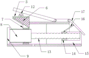
In order to achieve the purpose, the invention provides the following technical scheme: an intelligent cardiac and cerebral electrical signal detection device for hospitals comprises a device base, wherein a supporting seat is arranged on the device base, an adjusting mechanism for a patient to lie down is arranged on the upper surface of the supporting seat, the adjusting mechanism comprises a seat plate, a lying plate is arranged on the left side of the seat plate, a pressing plate is arranged on the lower surface of the lying plate, a sliding table is arranged on the lower surface of the pressing plate, a first sliding block is arranged on the lower surface of the sliding table, a first threaded rod is arranged inside the first sliding block, a positioning seat is arranged on the outer surface of the first threaded rod in a fixed-axis rotating mode, telescopic rods are arranged between the two sides of the pressing plate and the device base, a first spring is arranged inside the telescopic rods, mounting seats are arranged on the two sides of the seat plate and the lying plate, a second threaded rod is arranged on the outer surface of the first threaded rod in a fixed-axis rotating mode, a second sliding block is arranged on the outer side of the second threaded rod, and a first sliding seat is arranged on the outer side of the second sliding block, the upper surface of the second sliding block is provided with a supporting rod, and a pedal is arranged between the supporting rod and the seat plate.
Preferably, the device base is fixed connection with the telescopic link, the mount pad is fixed connection with clamp plate and supporting seat, the lower surface of clamp plate is the inclined plane with the upper surface of a slider, the inside of a slider is equipped with the screw thread corresponding with a threaded rod, the inside of No. two sliders is equipped with the screw thread corresponding with No. two threaded rods, the inside of a slide is equipped with the spout corresponding with No. two sliders, it is swing joint to support the pole and bedplate and footboard, the inside of a slider is the thread groove tangent of ball nut structure and this ball nut and a threaded rod.
Preferably, the adjusting mechanism is further provided with a feeding mechanism for ejecting the electrocardio patch to be detected, the feeding mechanism comprises a first rotating disc, the first rotary disc is fixedly arranged on the outer side of the first threaded rod, swing rods are arranged on two sides of the first rotary disc, a supporting block is arranged between the swing rod and the first rotary table in a limiting sliding manner, a fixed shaft of the swing rod is connected with a supporting frame, a second sliding seat is arranged on the outer side of the supporting frame, a sliding plate is fixedly connected on the outer side of the second sliding seat, an installation frame is arranged on the outer side of the swing rod, a first supporting rod is arranged between the installation frame and the swing rod in a fixed-shaft rotating manner, a pull rod is arranged between the first support rod and the sliding plate, a first push rod is arranged outside the pull rod and outside the first support rod in a fixed-axis rotating manner, a fixed shaft of the first ejector rod rotates to form a first ejector block, and a first sliding frame is connected to the outer side of the first ejector block in a sliding mode.
Preferably, the two sides of the first rotary table are provided with annular sliding grooves corresponding to the abutting blocks, the center of the first rotary table is located on the outer side of the first threaded rod, and the lower surface of the device base is provided with an opening corresponding to the first rotary table.
Preferably, the feeding mechanism further comprises a connecting seat, the connecting seat is fixedly arranged on the outer side of the sliding plate, the connecting seat is movably connected with the pull rod, a plurality of groups of openings are arranged on the outer side of the first sliding frame, openings corresponding to the first sliding frame are arranged on the outer side of the supporting seat, and the first sliding frame is fixedly arranged on the outer side of the supporting seat.
Preferably, the feeding device is further provided with a cleaning mechanism for adjusting the position of the electroencephalogram detection device and disinfecting a patch, the cleaning mechanism comprises two push rods, the push rods are fixedly arranged on the outer side of the first ejector block, the inner wall of each push rod is in threaded connection with an adjusting rod, the outer side of each adjusting rod is provided with a second turntable, the outer side of each second turntable is provided with a positioning frame, the corresponding lower surface of each positioning frame is provided with an installation table, the outer side of each second turntable is provided with a rotating rod, the outer side of each rotating rod is provided with a positioning ring, a hood is correspondingly arranged between the positioning rings, the inner wall of the hood is in threaded connection with a detection head, the outer side of each detection head is provided with a water storage tank, the inside of each water storage tank is provided with a water outlet pipe, the outer side of each water outlet pipe is provided with disinfection cotton, a piston is arranged inside the water storage tank, and the lower surface of each water storage tank is provided with a second ejector rod, the upper surface of No. two ejector pins is equipped with the push pedal, the lower surface of No. two ejector pins is equipped with the bracing piece No. two, the outside of outlet pipe is equipped with the spring No. two.
Preferably, the mounting table is fixedly arranged on the upper surface of the device base, the second support rod is fixedly arranged between the corresponding push rods, the rotating rod is located on the inner side of the positioning frame, the water storage tank is located on the outer side of the pressing plate, the outer side of the sterilized cotton is an arc surface, the water storage tank is of an L-shaped structure, the piston is located on the inner side of the water storage tank, and the push plate is located on the inner side of the water storage tank.
Preferably, feeding mechanism still includes two ratchets, the ratchets set firmly in the upper surface of No. two sliders, the meshing has a gear on the tooth of ratchets, the meshing has No. two gears on the tooth of a gear, the upper surface cover of No. two gears has connected the sleeve, telescopic inner wall threaded connection has No. three threaded rod, No. two kicking blocks of last fixed surface of No. three threaded rod, No. two outside sliding connection of kicking block has No. two balladecraws.
Compared with the prior art, the invention has the following beneficial effects:
through setting up adjustment mechanism, adopt the gravity that the patient couched, drive the clamp plate and remove, the clamp plate promotes along the slope below the slip table, adjusts footboard and service creeper to reach the effect of automatically regulated operating table, improved patient's comfort level.
Through setting up feeding mechanism, adjustment mechanism moves, and No. two threaded rods drive a carousel and rotate, drive two ejector pins and upwards rotate, and under the spacing slip of balladeur train, pop out the detection paster that is used for detecting the electrocardio with an kicking block upper surface to the effect that the medical staff of being convenient for operated the detection paster has been reached.
Through setting up clean mechanism, feeding mechanism moves, and a kicking block drives piston and push pedal and removes, sprays the antiseptic solution on the detection head to through the rotation of hood, automatic knot is at patient's head, thereby has reached clean disinfection and has made things convenient for the effect that the brain electricity detected.
The cooperation of the adjusting mechanism, the feeding mechanism and the cleaning mechanism is utilized to realize the effect of improving the synchronous detection of the ECG and the EEG of the patient, and simultaneously, the transmission advantage of the feeding mechanism is utilized to achieve the function of facilitating the medical staff to place medical supplies.
Drawings
FIG. 1 is a schematic perspective view of the present invention;
FIG. 2 is a sectional side view of the adjusting mechanism of the present invention;
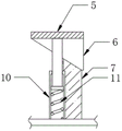
FIG. 3 is a cross-sectional side view of the telescoping pole of the present invention;
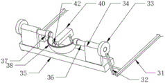
FIG. 4 is a schematic perspective view of the feeding mechanism of the present invention;
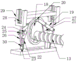
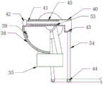
FIG. 5 is a schematic perspective view of the cleaning mechanism of the present invention;
FIG. 6 is a cross-sectional side view of the cleaning mechanism of the present invention;
fig. 7 is a schematic perspective view of the rack bar of the present invention.
In the figure: 1. a device base; 2. a supporting seat; 3. a seat plate; 4. a lying board; 5. pressing a plate; 6. a sliding table; 7. a first sliding block; 8. a first threaded rod; 9. positioning seats; 10. a telescopic rod; 11. a first spring; 12. a mounting seat; 13. a second threaded rod; 14. a second sliding block; 15. a first sliding seat; 16. a support rod; 17. a pedal; 18. a first turntable; 19. a swing rod; 20. a resisting block; 21. a support frame; 22. a second sliding seat; 23. a slide plate; 24. a mounting frame; 25. a first support rod; 26. a pull rod; 27. a first ejector rod; 28. a first top block; 29. a first carriage; 30. a connecting seat; 31. a push rod; 32. adjusting a rod; 33. a second turntable; 34. a positioning frame; 35. an installation table; 36. a rotating rod; 37. a positioning ring; 38. a head cover; 39. a detection head; 40. a water storage tank; 41. a water outlet pipe; 42. sterilizing cotton; 43. pushing the plate; 44. a second support rod; 45. a second spring; 46. a rack bar; 47. a first gear; 48. a second gear; 49. a sleeve; 50. a third threaded rod; 51. a second top block; 52. a second carriage; 53. a piston; 54. and a second ejector rod.
Detailed Description
The technical solutions in the embodiments of the present invention will be clearly and completely described below with reference to the drawings in the embodiments of the present invention, and it is obvious that the described embodiments are only a part of the embodiments of the present invention, and not all of the embodiments. All other embodiments, which can be derived by a person skilled in the art from the embodiments given herein without making any creative effort, shall fall within the protection scope of the present invention.
Example one
Referring to fig. 1 to 6, the present invention provides a technical solution: an intelligent cardiac and cerebral electric signal detection device for hospitals comprises a device base 1, wherein a supporting seat 2 is arranged on the device base 1, an adjusting mechanism for a patient to lie down is arranged on the upper surface of the supporting seat 2, the adjusting mechanism comprises a seat plate 3, a lying plate 4 is arranged on the left side of the seat plate 3, a pressing plate 5 is arranged on the lower surface of the lying plate 4, a sliding table 6 is arranged on the lower surface of the pressing plate 5, the sliding table 6 is fixedly connected with the pressing plate 5, a first sliding block 7 is arranged on the lower surface of the sliding table 6, a first threaded rod 8 is arranged inside the first sliding block 7, a positioning seat 9 is arranged on the outer surface of the first threaded rod 8 in a fixed-axis rotation mode, the positioning seat 9 is positioned on the upper surface of the device base 1, telescopic rods 10 are arranged between the two sides of the pressing plate 5 and the device base 1, a first spring 11 is arranged inside the telescopic rods 10, the patient can lie down more stably, and when the patient sits up, in order to realize rebounding of service creeper 4, bedplate 3 all is equipped with mount pad 12 with the both sides of service creeper 4, and 8 surface dead axles of threaded rod rotate and have No. two threaded rods 13, and the outside of No. two threaded rods 13 is equipped with slider 14 No. two, and the outside of slider 14 No. two is equipped with slide 15 No. one, and the upper surface of slider 14 No. two is equipped with and supports pole 16, supports to be equipped with footboard 17 between pole 16 and the bedplate 3, plays the effect of supporting patient's shank.
The device is characterized in that a base 1 is fixedly connected with an expansion link 10, a mounting seat 12 is fixedly connected with a pressing plate 5 and a supporting seat 2, the lower surface of the pressing plate 5 and the upper surface of a first slide block 7 are inclined planes, a lying plate 4 is driven to move downwards by the weight of a patient, the lying plate 4 drives the pressing plate 5 to move downwards by the mounting seat 12 as a fulcrum, the pressing plate 5 drives a sliding table 6 to move downwards, the inside of the first slide block 7 is of a ball nut structure, the ball nut is tangent to a thread groove of a first threaded rod 8, the inside of a second slide block 14 is provided with threads corresponding to a second threaded rod 13, the second threaded rod 13 drives the second slide block 14 to move along the first slide block 15 when rotating, the inside of the first slide block 15 is provided with a sliding groove corresponding to the second slide block 14, a support rod 16 is movably connected with a seat plate 3 and a pedal 17, and when the second slide block 14 moves, the support rod 16 is pushed to rotate upwards, thereby pushing the pedal 17 to rotate upwards to support the legs of the patient and improving the comfort level of the patient during lying.
The adjusting mechanism is also provided with a feeding mechanism for popping up the electrocardio patch to be detected, the feeding mechanism comprises a first rotary table 18, the first rotary table 18 and a first threaded rod 8 are fixedly arranged on the outer side of the first threaded rod, both sides of the first rotary table 18 are provided with swing rods 19, a butting block 20 is arranged between the swing rods 19 and the first rotary table 18 in a limiting sliding manner, a fixed shaft of each swing rod 19 is connected with a support frame 21, the support frames 21 and the swing rods 19 are movably connected, the outer side of each support frame 21 is provided with a second slide seat 22, the outer side of the second slide seat 22 is fixedly connected with a sliding plate 23, the inner wall of the second slide seat 22 is in threaded connection with a sliding groove corresponding to the sliding plate 23, the sliding plate 23 is fixedly connected with the support frames 21, the outer side of the swing rods 19 is provided with a mounting frame 24, the mounting frame 24 is fixedly connected with the swing rods 19, a first supporting rod 25 is arranged between the mounting frame 24 and the swing rods 19 in a fixed shaft rotating manner, a pull rod 26 is arranged between the first supporting rod 25 and the sliding plate 23, a first push rod 27 is arranged on the outer side of the pull rod 26 and positioned on the first supporting rod 25, a first ejector block 28 is arranged on the fixed-axis rotation of the first ejector rod 27, a first sliding frame 29 is connected to the outer side of the first ejector block 28 in a sliding mode, and the first sliding frame 29 and the first ejector block 28 are used for placing the electrocardio patch for detection.
The two sides of the first rotary table 18 are provided with annular sliding grooves corresponding to the abutting blocks 20, so that the abutting blocks 20 can be driven to rotate along the outer side of the first rotary table 18 conveniently, the central point of the first rotary table 18 is located on the outer side of the first threaded rod 8, and the lower surface of the device base 1 is provided with an opening corresponding to the first rotary table 18, so that the first rotary table 18 can rotate conveniently.
The feeding mechanism further comprises a connecting seat 30, the connecting seat 30 is fixedly arranged on the outer side of the sliding plate 23, the connecting seat 30 is movably connected with the pull rod 26, the pull rod 26 pulls the sliding plate 23 to move when moving, a plurality of groups of openings are formed in the outer side of the first sliding frame 29, openings corresponding to the first sliding frame 29 are formed in the outer side of the supporting seat 2, the first push rod 27 can swing conveniently, and the first sliding frame 29 is fixedly arranged on the outer side of the supporting seat 2.
The feeding device is also provided with a cleaning mechanism for adjusting the position of the electroencephalogram detection equipment and sterilizing patches, the cleaning mechanism comprises two push rods 31, the push rods 31 are fixedly arranged on the outer side of the first ejector block 28, the inner wall of each push rod 31 is in threaded connection with an adjusting rod 32, the outer side of each adjusting rod 32 is provided with a second turntable 33, one end of each adjusting rod 32 is movably connected with the surface of the second turntable 33, the second turntable 33 is driven to rotate when the adjusting rods 32 rotate, the outer side of each second turntable 33 is provided with a positioning frame 34, the lower surface of the corresponding positioning frame 34 is provided with an installation table 35, the positioning frames 34 are fixedly connected with the installation tables 35, the outer side of each second turntable 33 is provided with a rotating rod 36, the second turntable 33 drives the rotating rod 36 to rotate when rotating, the outer side of each rotating rod 36 is provided with a positioning ring 37, the positioning rings 37 are fixedly connected with the rotating rods 36, a hood 38 is arranged between the corresponding positioning rings 37, and the hood 38 is fixedly connected with the positioning rings 37, the inner wall of the hood 38 is in threaded connection with a detection head 39 for detecting brain waves of a patient, a water storage tank 40 is arranged on the outer side of the detection head 39 and used for storing disinfectant, a water outlet pipe 41 is arranged inside the water storage tank 40, disinfectant cotton 42 is arranged on the outer side of the water outlet pipe 41 and used for installing and cleaning the disinfectant cotton of the detection head 39, a piston 53 is arranged on the outer side of the water outlet pipe 41 and located inside the water storage tank 40, a second ejector rod 54 is arranged on the lower surface of the water storage tank 40, a push plate 43 is arranged on the upper surface of the second ejector rod 54, a second support rod 44 is arranged on the lower surface of the second ejector rod 54, a second spring 45 is arranged on the outer side of the water outlet pipe 41 and used for returning to the piston 53, the hood 38 is driven to rotate by a rotating rod 36, and when the disinfection cotton 38 passes through the disinfectant cotton 42, the disinfection cotton 42 is pushed to move towards the inner side of the water storage tank 40, the water outlet pipe 41 is driven by the disinfectant cotton 53 and moves along the inner side of the water storage tank 40, the disinfectant enters the disinfectant cotton on the disinfectant cotton 42 from the water outlet pipe 41 to disinfect the passing detection head 39.
Installation platform 35 sets firmly in the upper surface of device base 1, No. two bracing pieces 44 set firmly between the push rod 31 that corresponds, bull stick 36 is located the inboard of locating rack 34, storage water tank 40 is located the outside of clamp plate 5, the outside of aseptic cotton 42 is the cambered surface, be convenient for install aseptic cotton, storage water tank 40 is "L" shape structure, be convenient for piston 53 and push pedal 43 to remove, piston 53 is located the inboard of storage water tank 40, push pedal 43 is located the inboard of storage water tank 40, push rod 31 is when removing, No. two bracing pieces 44 drive No. two ejector pins 54 and remove, No. two ejector pins 54 promote push pedal 43 along the inside of storage water tank 40, use with piston 53 combination, carry out the bidirectional extrusion antiseptic solution, improve water spray efficiency.
Example two
Referring to fig. 7, the present embodiment is substantially the same as the first embodiment, except that the feeding mechanism is replaced by two rack bars 46, the rack bars 46 are fixedly disposed on the upper surface of the second slider 14, a first gear 47 is engaged with the teeth of the rack bars 46, a second gear 48 is engaged with the teeth of the first gear 47, the first gear 47 drives the second gear 48 to rotate when rotating, a sleeve 49 is sleeved on the upper surface of the second gear 48, a third threaded rod 50 is connected with the inner wall of the sleeve 49 through a thread, a thread corresponding to the third threaded rod 50 is disposed inside the sleeve 49, so that the sleeve 49 drives the third threaded rod 50 to move upward when rotating, a second ejector block 51 is fixedly connected to the upper surface of the third threaded rod 50, the second ejector block 51 is movably connected to the third threaded rod 50, a second carriage 52 is slidably connected to the outer side of the second ejector block 51, and when the third threaded rod 50 moves, the second ejector block 51 is pushed to move along the inner side of the second carriage 52, used for popping up a paster for detecting electrocardio.
The working principle is as follows: the hospital uses the intelligent heart brain electrical signal detection device, when using, the disinfection cotton is installed and disinfected cotton 42, then the patient lies on the lying plate 4, the lying plate 4 is driven to move downwards by gravity, the lying plate 4 takes the mounting seat 12 as the pivot to drive the pressing plate 5 to move downwards, the pressing plate 5 drives the sliding table 6 to move downwards, the sliding table 6 and the sliding block 7 are driven to move towards the left side by the inclined plane corresponding to the sliding block 7, meanwhile, the ball nut structure in the sliding block 7 is utilized to reduce the friction force with the threaded rod 8, the threaded rod 8 is driven to rotate by the movement of the sliding block 7, in the prior art, the threaded rod 8 can adopt the ball screw, the threaded rod 8 drives the threaded rod 13 to rotate, the threaded rod 13 passes through the sliding block 14 and the corresponding thread, and the sliding block 15 is positioned to drive the sliding block 14 to move towards the right, no. two sliders 14 drive and support 16 rotations of pole, drive footboard 17 upwards and rotate, support patient's shank from this, simultaneously, telescopic link 10 uses with a spring 11 combination, makes the speed that the patient couched more steady to when the patient sat up, make service creeper 4 kick-backs, thereby reached the effect of automatically regulated operating table, improved patient's comfort level.
When the second threaded rod 13 rotates, the first rotary plate 18 is driven to rotate, and by utilizing the distance between the center of the first rotary plate 18 and the center of the first threaded rod 8, when the first rotary plate 18 rotates, the grooves on the two sides of the first rotary plate drive the abutting block 20 to move leftwards and downwards, the abutting block 20 drives the swing rod 19 to swing, the other side of the swing rod 19 drives the first ejector rod 27 to move upwards, meanwhile, the first support rod 25 rotating along the fixed shaft outside the swing rod 19 presses the pull rod 26 to move downwards, the pull rod 26 is used in combination with the sliding plate 23 to drive the sliding plate 23 to move in the groove of the second sliding seat 22, the first ejector rod 27 drives the first ejector block 28 to move along the inner side of the first sliding seat 29, so that the detection patch for detecting electrocardio on the upper surface of the first ejector block 28 is ejected, and the effect of facilitating the operation of the detection patch by medical staff is achieved.
When the first ejector block 28 moves, the corresponding push rod 31 is driven to move upwards, the push rod 31 pushes the adjusting rod 32 to rotate along the outer side of the second turntable 33, thereby driving the second rotary table 33 to rotate, the second rotary table 33 driving the rotary rods 36 to rotate, the two groups of rotary rods 36 driving the head cover 38 to rotate, is used for covering the head of the patient, meanwhile, the head cover 38 pushes the sterilizing cotton 42 to move when passing through the sterilizing cotton 42, the sterilizing cotton 42 drives the water outlet pipe 41 to move along the inner side of the water storage tank 40, so that the disinfectant can enter the disinfectant cotton on the disinfectant cotton 42 from the water outlet pipe 41 through the piston 53 and the disinfectant in the water storage tank 40, the detection head 39 is sterilized, the push rod 31 drives the second push rod 54 to move through the second support rod 44 when moving, the second push rod 54 pushes the push plate 43 to further extrude the disinfectant in the water storage tank 40 along the inside of the water storage tank 40, and therefore the effect of cleaning and sterilizing is achieved.
Although embodiments of the present invention have been shown and described, it will be appreciated by those skilled in the art that changes, modifications, substitutions and alterations can be made in these embodiments without departing from the principles and spirit of the invention, the scope of which is defined in the appended claims and their equivalents.