CN1135503C - Coin detection method and device, coin identification method, and coin or token operation device - Google Patents
Coin detection method and device, coin identification method, and coin or token operation device Download PDFInfo
- Publication number
- CN1135503C CN1135503C CNB971944202A CN97194420A CN1135503C CN 1135503 C CN1135503 C CN 1135503C CN B971944202 A CNB971944202 A CN B971944202A CN 97194420 A CN97194420 A CN 97194420A CN 1135503 C CN1135503 C CN 1135503C
- Authority
- CN
- China
- Prior art keywords
- coin
- laser
- laser beam
- edge
- coins
- Prior art date
- Legal status (The legal status is an assumption and is not a legal conclusion. Google has not performed a legal analysis and makes no representation as to the accuracy of the status listed.)
- Expired - Fee Related
Links
Images


Classifications
-
- G—PHYSICS
- G07—CHECKING-DEVICES
- G07D—HANDLING OF COINS OR VALUABLE PAPERS, e.g. TESTING, SORTING BY DENOMINATIONS, COUNTING, DISPENSING, CHANGING OR DEPOSITING
- G07D5/00—Testing specially adapted to determine the identity or genuineness of coins, e.g. for segregating coins which are unacceptable or alien to a currency
- G07D5/02—Testing the dimensions, e.g. thickness, diameter; Testing the deformation
-
- G—PHYSICS
- G07—CHECKING-DEVICES
- G07D—HANDLING OF COINS OR VALUABLE PAPERS, e.g. TESTING, SORTING BY DENOMINATIONS, COUNTING, DISPENSING, CHANGING OR DEPOSITING
- G07D5/00—Testing specially adapted to determine the identity or genuineness of coins, e.g. for segregating coins which are unacceptable or alien to a currency
- G07D5/005—Testing the surface pattern, e.g. relief
-
- G—PHYSICS
- G07—CHECKING-DEVICES
- G07D—HANDLING OF COINS OR VALUABLE PAPERS, e.g. TESTING, SORTING BY DENOMINATIONS, COUNTING, DISPENSING, CHANGING OR DEPOSITING
- G07D5/00—Testing specially adapted to determine the identity or genuineness of coins, e.g. for segregating coins which are unacceptable or alien to a currency
- G07D5/10—Testing the rim, e.g. the milling of the rim
Landscapes
- Physics & Mathematics (AREA)
- General Physics & Mathematics (AREA)
- Testing Of Coins (AREA)
- Length Measuring Devices By Optical Means (AREA)
- Investigating Materials By The Use Of Optical Means Adapted For Particular Applications (AREA)
Abstract
Description
技术领域technical field
本发明涉及硬币检验装置和辨认硬币的方法。The present invention relates to a coin checking device and a method for identifying coins.
背景技术Background technique
硬币检验系统或硬币估价器用于例如自动售货机与电话机中辨认或辨别不同的硬币。有多种可用的机电和电磁硬币辨别器,它们用于各种不同的用场,如自动售货机,公用或私用电话机等。这样的辨别可以用于多种类型自动售货机或投币机器,如在飞机场、火车站、赌博机、工厂、学校、医院、饭店或海滨。Coin verification systems or coin valuers are used, for example, in vending machines and telephones to identify or discriminate between different coins. There are a variety of electromechanical and electromagnetic coin acceptors available, and they are used in a variety of different applications, such as vending machines, public or private telephones, and the like. Such discrimination can be used in many types of vending or coin-operated machines, such as in airports, railway stations, gaming machines, factories, schools, hospitals, restaurants or seasides.
在自动售货机和电话机中运用的这些硬币辨别常常在它们能够辨别不同类型硬币的数量方面受到严格的限制。The coin discriminations used in vending machines and telephones are often severely limited in the number of different types of coins they can discriminate.
英国公开的专利申请号GB-A-2,212,313公开了硬币分拣装置,在该装置中,一束光以一个角度直射在硬币的边缘。如果硬币具有合适的直径,那么,光束的一部分以直线穿过进入第一检测器,且光束的一部分被发射(漫射)到不在直线穿过路径上的第二个检测器。GB-A-2,212,313系统依靠两个检测器接受的一些光束来辨识硬币具有合适的直径以部分反射光束。如果每个检测器都没有检测到任何光束或直线穿过的检测器接受所有的光线,那么,这个硬币不具有所希望的直径。这个系统建议将激光二极管作为一种可能的光源。British Published Patent Application No. GB-A-2,212,313 discloses a coin sorting device in which a beam of light is directed at the edge of a coin at an angle. If the coin has the proper diameter, then a portion of the beam passes in a straight line into the first detector and a portion of the beam is emitted (diffused) to a second detector which is not on the straight line path. The GB-A-2,212,313 system relies on a number of beams received by two detectors to identify coins of suitable diameter to partially reflect the beams. If none of the beams are detected by each detector or all the light is received by the detectors that pass straight through, then the coin does not have the desired diameter. This system suggests a laser diode as a possible light source.
欧洲公开专利申请EP-A-0,629,979公开了一种使用光电流和线性传感器阵列来确保提供具有正确大小新硬币的系统。European Published Patent Application EP-A-0,629,979 discloses a system that uses photocurrent and linear sensor arrays to ensure that new coins of the correct size are provided.
发明内容Contents of the invention
根据本发明的第一个方面,提供一种检验硬币的方法,在这种方法中,激光束直射到硬币的表面,并且用激光检测器来获得硬币表面尺寸特征的指示,其特征在于所说的激光检测器检测硬币在哪儿截取激光束,硬币在哪儿不截取激光束。According to a first aspect of the present invention there is provided a method of verifying coins in which a laser beam is directed onto the surface of the coin and a laser detector is used to obtain an indication of dimensional features of the coin surface, characterized in that The laser detector detects where the coin intercepts the laser beam and where the coin does not intercept the laser beam.
硬币表面至少一个长条的至少一个部分的长度被确定或被检测。The length of at least one portion of at least one strip of the coin surface is determined or detected.
能够确定或检测硬币表面多个长条的至少一部分的长度。The length of at least a portion of the plurality of strips on the face of the coin can be determined or detected.
光束可以一个接一个地扫描长条或其部分。The beam can scan the sliver or its sections one after the other.
光束可以具有扇形形状以同时照射在这个或每个所说长条的全部或其部分。The light beam may have a fan shape to impinge on all or part of the or each said strip simultaneously.
激光检测器可以包括许多一个挨一个的象素,每一个能分别检测激光辐射。The laser detector may comprise a plurality of pixels next to each other, each capable of separately detecting laser radiation.
最好光束是静止的,硬币移过光束。Preferably the beam is stationary and the coin moves across the beam.
当硬币移过光束时,硬币可以旋转。Coins can spin as they move across the beam.
当硬币移过光束时,硬币可以沿导向机构移动。As the coin moves through the light beam, the coin can move along the guide mechanism.
当硬币移过光束时,硬币可以是自由下落状态。The coin can be in free fall as it moves through the beam.
这个或每个所说长条的一端可以位于硬币的边缘,长条的另一端可以位于不在硬币边缘的预定位置。One end of the or each said strip may be located on the edge of the coin and the other end of the strip may be located at a predetermined location which is not on the edge of the coin.
第二个激光束可以射在硬币的边缘且被检测,以便确定硬币边缘的特征和/或厚度。A second laser beam can be shot at the edge of the coin and inspected to determine the features and/or thickness of the edge of the coin.
可以确定或检测硬币边缘凹槽和/或凸条的尺寸特征。Dimensional features of coin edge grooves and/or ridges may be determined or detected.
可以计算硬币边缘预定距离内的凹槽和/或凸条的数量。The number of grooves and/or ridges within a predetermined distance from the edge of the coin may be counted.
第二个激光束可以从第一个提到的激光束中获得。The second laser beam can be obtained from the first mentioned laser beam.
第二个激光束可以通过一个使第一个提到的激光束一部分偏转的棱镜装置来从第一个提到的激光束中获得。The second laser beam can be obtained from the first mentioned laser beam by a prism arrangement which deflects a part of the first mentioned laser beam.
最好,在硬币和激光的交汇处,硬币完全垂直于激光束。Preferably, at the intersection of the coin and the laser, the coin is perfectly perpendicular to the laser beam.
在硬币与激光的交汇处,激光束大致可以具有激光辐射的薄板形状。At the intersection of the coin and the laser, the laser beam may roughly have the shape of a thin plate of laser radiation.
根据本发明的第二方面,用于硬币检测的装置包括:According to a second aspect of the present invention, means for coin detection comprises:
一个所设置的适合于激光束直射到硬币表面的激光源。A laser source arranged to direct the laser beam onto the surface of the coin.
一个激光检测器,以及a laser detector, and
一个所设置的适合于由激光检测器的输出获得硬币表面尺寸特征指示的信号处理器,其特征在于:A signal processor adapted to obtain an indication of coin surface size characteristics from the output of the laser detector, characterized by:
所说设置的激光检测器适合于检测硬币在哪儿拦截激光以及硬币在哪儿不拦截激光。The laser detector arrangement described is adapted to detect where the coin intercepts the laser light and where the coin does not intercept the laser light.
最好,该装置适合于确定或险测硬币表面至少一个长条的至少一个部分的长度。Preferably, the device is adapted to determine or measure the length of at least one portion of at least one strip on the face of the coin.
该装置能够适用于确定或检测硬币表面多个长条的至少一个部分的长度。The device can be adapted to determine or detect the length of at least one portion of the plurality of strips on the face of the coin.
光束能够适用于一个接一个地扫描所说长条或所说的部分。The light beam can be adapted to scan said strips or said sections one after the other.
光束可以呈扇形,以便同时照到这个或每个所说长条的全部,或其中的一部分。The light beam may be fanned so as to simultaneously illuminate the or each said strip in its entirety, or in part thereof.
最好,激光源和由此发出的光束是静止的,该装置适用于使硬币移过光束。Preferably, the laser source and thus the beam of light is stationary and the arrangement is adapted to move the coin across the beam.
该装置可以包括当硬币移过时硬币沿其移动的导向机构。The device may include a guide mechanism along which the coin moves as it moves past.
该装置可以适用于在运行时当硬币通过光束时,硬币在自由下落中。The device can be adapted to operate with the coin in free fall as it passes through the light beam.
在应用中,这个或每个所说长条的一端可以在硬币的边缘,长条的另一端可以在不位于硬币边缘的一预定位置。In practice, one end of the or each said strip may be on the edge of the coin and the other end of the strip may be at a predetermined location not on the edge of the coin.
该装置可以包括使第二个激光束射在硬币边缘的装置,用于检测硬币截取第二个光束位置的装置,和用于确定硬币边缘特征和/或厚度的装置。该装置可以包括用于根据第一个提到的激光束来驱动第二个激光束的装置。The means may include means for directing the second laser beam at the edge of the coin, means for detecting where the coin intercepts the second beam, and means for determining the character and/or thickness of the edge of the coin. The device may comprise means for driving the second laser beam in dependence on the first mentioned laser beam.
用于根据第一个提到的激光束来获得第二个激光束的装置可以包括用于使第一个提到的激光束一部分偏转的棱镜。The means for obtaining the second laser beam from the first mentioned laser beam may comprise a prism for deflecting a part of the first mentioned laser beam.
激光检测器可以包括许多一个挨一个的象素,每个能分别检测激光辐射。The laser detector may comprise a plurality of pixels next to each other, each capable of separately detecting laser radiation.
根据本发明的第三个方面,提供的硬币检测装置包括:According to a third aspect of the present invention, the coin detection device provided comprises:
一个合适的设置成使激光束直射在硬币上的激光源,a laser source suitably arranged so that the laser beam is directed at the coin,
一个合适的设置成以检测硬币拦截激光位置和硬币不拦截激光位置的激光检测器,和a laser detector suitably arranged to detect the position where the coin intercepts the laser and the position where the coin does not intercept the laser, and
一个设置成使硬币能沿规定的路径通过的硬币导向机构,沿着该路径硬币能够截取在激光源与激光检测器之间通过的一部分激光束;和a coin guiding mechanism arranged to allow the coin to pass along a prescribed path along which the coin intercepts a portion of the laser beam passing between the laser source and the laser detector; and
一个合适的设置成用于获取激光检测器输出的信号处理器;a signal processor suitably arranged to obtain the output of the laser detector;
其中所截取的激光束比例至少提供硬币几何尺寸的一种度量,通过将硬币所说的度量同已知多个硬币的相应度量相比较,可以识别硬币。Wherein the ratio of the intercepted laser beam provides at least one measure of the coin's geometry, the coin can be identified by comparing said measure of the coin with corresponding measures of a known plurality of coins.
为了将所说表面度量和厚度同已知多个硬币的相应度量相比较,至少一个度量可以由所说硬币表面的几何尺寸组成,另一个度量可以由所说硬币的厚度组成。In order to compare said surface measures and thicknesses with corresponding measures of a known plurality of coins, at least one measure may consist of the geometry of the surface of said coin and another measure may consist of said coin's thickness.
可以重复测量许多几何尺寸以提供所说硬币表面范围的完整区域度量,通过将所说硬币的所说区域度量同已知多个硬币的相应区域度量相比较,可以识别所说的硬币。A number of geometric dimensions can be repeatedly measured to provide a complete area measure of the surface extent of the coin, and the coin can be identified by comparing the area measure of the coin with corresponding area measures of a known plurality of coins.
可以确定或检测硬币边缘凹槽和/或凸条的尺寸特征。Dimensional features of coin edge grooves and/or ridges may be determined or detected.
可以计算硬币边缘预定距离内凹槽和/或凸条的数量。The number of grooves and/or ridges within a predetermined distance from the edge of the coin can be counted.
所说硬币几何尺寸的度量及所说多个已知硬币的所说相应度量都可能与比直径小或在不规则形状硬币的情况下比每个相应硬币最大截面小的硬币尺寸有关。The measure of said coin geometry and said corresponding measure of said plurality of known coins may be related to a coin size smaller than the diameter or, in the case of irregularly shaped coins, smaller than the largest cross-section of each respective coin.
在所说激光源和所说激光检测器之间通过的激光束可以经迂回的非直路径在其中通过。The laser beam passing between said laser source and said laser detector may pass therethrough via a detoured non-straight path.
激光束可以通过一个或多个镜子或棱镜沿着所说的迂回非直的路径直射。The laser beam may be directed through one or more mirrors or prisms along said devious non-straight path.
该路径包括具有下边缘的通道,沿着该通道所说硬币能通过本装置并在通道一部分的周边上继续得到所说通道的所说下边缘支持。The path includes a channel having a lower edge along which said coin can pass through the device and continue to be supported by said lower edge of said channel over a portion of the perimeter of the channel.
可以安装激光源以使激光束由所说通道的一侧基本与通道中所说硬币的主平面相垂直地直射到所说通道的另一侧,以便激光束通过所说通道的所说部分时被所说硬币的上部分区域所截取。The laser source can be installed so that the laser beam is directed from one side of the passage to the other side of the passage substantially perpendicular to the main plane of the coin in the passage, so that when the laser beam passes through the said part of the passage Intercepted by the upper region of said coin.
激光检测器可以包括许多一个挨一个象素的线性阵列,每个象素能分别检测激光辐射。The laser detector may comprise a linear array of many pixels next to each other, each pixel capable of individually detecting laser radiation.
该阵列基本上沿平行于所说主平面且在与沿着通道所说部分硬币通过方向相垂直的方向上伸展,并且可以具有与所说下部边缘间隔第一距离空间的下端,第一距离小于本装置所用一些硬币的最小直径,上端与所说下边缘间隔第二距离,第二距离大于所说多个硬币的最大直径,所说激光检测装置可用来依据所说象素数目产生输出,从这些象素,在多个连续采样的瞬间,沿着通道所说部分通过的硬币阻止所说的激光束,以便所说的输出能与预定的参考数据记录相比较以确认哪些记录与所说输出相对应。The array extends substantially in a direction parallel to said principal plane and perpendicular to the direction of passage of coins along said portion of the channel, and may have a lower end spaced from said lower edge by a first distance space, the first distance being less than The smallest diameter of some coins used by the device, the upper end is spaced from said lower edge by a second distance, the second distance is greater than the largest diameter of said plurality of coins, said laser detection means can be used to generate an output based on said number of pixels, from These pixels, at a plurality of successive sampling instants, block the laser beam from a coin passing along said portion of the channel, so that said output can be compared with predetermined reference data records to determine which records are consistent with said output Corresponding.
硬币可以沿所说路径通过以便在交汇点所说硬币完全与所说激光束相垂直。A coin may be passed along said path so that at the intersection point said coin is completely perpendicular to said laser beam.
最好,由硬币拦截的激光束在所说交汇点处基本上呈激光辐射的薄板形状。Preferably, the laser beam intercepted by the coin has substantially the shape of a thin plate of laser radiation at said intersection point.
根据本发明的第四个方面,提供的硬币检测装置包括:According to a fourth aspect of the present invention, the coin detection device provided includes:
确定硬币通道具有下边缘的硬币导向机构,沿着该通道所说硬币能通过本装置并在通道的周边上继续得到所说下边缘的支持;coin guide means defining a coin passage having a lower edge along which said coin can pass through the device and continue to be supported by said lower edge on the periphery of the passage;
所安装的激光源,用于由所说通道一部分的一侧基本与通道中所说硬币的主平面相垂直地直射到所说通道一部分的另一侧,以便激光束通过所说通道的所说部分时被所说硬币的上部分区域所截取;和The laser source that is installed is used for directly directing to the other side of said passage part by the one side of said passage part substantially perpendicular to the main plane of said coin in passage, so that said laser beam passes through said passage. is partially intercepted by the upper region of said coin; and
一个在通道所说部分的所说另一侧包括激光接受位置线性阵列的激光检测器,该阵列基本上沿平行于所说主平面且同与沿着通道所说部分硬币通过方向相垂直的方向上伸展,并且具有与所说下部边缘间隔第一距离空间的下端,第一距离小于本装置所用一些硬币的最小直径,上端与所说下边缘间隔第二距离,第二距离大于所说多个硬币的最大直径,所说激光检测装置可用来依据所说激光接受位置数产生输出,从这些位置上,在多个连续采样的瞬间,沿着通道所说部分通过的硬币阻止所说的激光束,以便所说的输出能与预定的参考数据记录相比较以确认哪些记录与所说输出相对应。a laser detector comprising a linear array of laser receiving locations on said other side of said portion of the channel, the array being substantially oriented in a direction parallel to said principal plane and perpendicular to the direction of passage of coins along said portion of the channel extending upward, and having a lower end spaced from said lower edge by a first distance space, the first distance being less than the minimum diameter of some coins used in the device, and an upper end spaced from said lower edge by a second distance, the second distance being greater than said plurality of coins the maximum diameter of a coin for which said laser detection means is operable to generate an output dependent on the number of said laser receiving positions from which a coin passing along said portion of the channel blocks said laser beam at a plurality of successive sampling instants , so that said output can be compared with predetermined reference data records to determine which records correspond to said output.
该装置可以包括多个激光源和多个激光检测器。The device may include multiple laser sources and multiple laser detectors.
根据本发明的第五个方面,提供的辨认硬币的方法包括以下步骤:According to a fifth aspect of the present invention, the method for identifying coins provided includes the following steps:
i)使硬币沿着一个规定通道通过以便所说的硬币截取在激光辐射源和激光检测器之间通过的部分激光束;i) passing the coin along a defined path so that said coin intercepts part of the laser beam passing between the laser radiation source and the laser detector;
ii)测量被截取的所说激光束的比例作为确定所说硬币几何尺寸的至少一个度量的方法;ii) measuring the fraction of said laser beam intercepted as a means of determining at least one measure of said coin's geometry;
iii)将所说硬币的所说度量同已知多个硬币相应度量相比较以辨认所说的硬币。iii) comparing said measure of said coin to corresponding measures of a known plurality of coins to identify said coin.
至少一个度量可以由所说硬币表面的几何尺寸组成;该方法可以进一步包括确定所说硬币厚度度量的步骤以便将所说度量同所说多个已知硬币的度量相比较。At least one measure may consist of surface geometry of said coin; and the method may further comprise the step of determining said coin thickness measure for comparing said measure to measures of said plurality of known coins.
该方法可以进一步包括确定所说硬币多个几何尺寸的度量的步骤以提供所说硬币表面范围的完整区域度量,通过将所说硬币的区域度量同所说多个已知硬币的相应区域度量相比较,可以辨认所说硬币。The method may further comprise the step of determining a plurality of geometric dimensions of said coin to provide a complete area measure of the face extent of said coin by comparing the area measures of said coin with corresponding area measures of said plurality of known coins By comparison, the coin can be identified.
该方法可以包括确定或检测在硬币边缘凹槽和/或凸条尺寸特征的步骤。The method may include the step of determining or detecting dimensional features of the grooves and/or ridges on the edge of the coin.
该方法可以进一步包括计算在所说硬币预定距离内凹槽和/或凸条数量的步骤。The method may further comprise the step of counting the number of grooves and/or ridges within a predetermined distance of said coin.
在本说明书和所附的权利要求中,术语“激光源”和“激光检测器”应当被认为覆盖了分别实现提供激光辐射源和检测激光辐射功能的任何装置或装置的组合,假定每个激光源和激光检测器都能实现如权利要求所述的使本发明运转起来的功能,那么该激光源和激光检测器每一个都可能是单独的部件、部件的一部分或部件的组合。In this specification and the appended claims, the terms "laser source" and "laser detector" shall be considered to cover any device or combination of devices which respectively perform the functions of providing a source of laser radiation and detecting laser radiation, assuming that each laser If both the source and the laser detector can perform the functions described in the claims to make the invention work, then the laser source and the laser detector can each be a separate component, a part of a component or a combination of components.
该发明更进一步的优点将由所附的权利要求变得更加明显,因此将这些权利要求的主题内容引入到详细说明中。Still further advantages of the invention will become apparent from the appended claims, the subject-matter of which is therefore incorporated into the detailed description.
附图说明Description of drawings
为了更全面地理解该发明,将参考附图仅通过举例描述本发明的实施例,在附图中:For a more complete understanding of the invention, embodiments of the invention will be described, by way of example only, with reference to the accompanying drawings, in which:
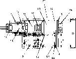
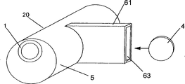
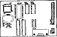
图1表示硬币检测装置的第一个实施例的截面视图;Figure 1 shows a cross-sectional view of a first embodiment of a coin detection device;
图1A表示在第一个实施例中相对方位的各部件;Figure 1A shows the components in relative orientation in the first embodiment;
图1B表示图1实施例中所用的为了描述而没有内部部件的壳体截面侧视图;Figure 1B shows a sectional side view of the housing used in the embodiment of Figure 1 without internal components for purposes of illustration;
图1C表示图1B壳体的外部侧视图;Figure 1C shows an external side view of the housing of Figure 1B;
图1D表示图1B壳体的概观图;Figure 1D shows an overview of the housing of Figure 1B;
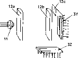
图2表示硬币检测装置第二个实施例的截面侧视图;Figure 2 shows a cross-sectional side view of a second embodiment of the coin detection device;
图2A表示在第二个实施例硬币检测装置中相对方位上的各个部件;Fig. 2A shows each component on the relative orientation in the coin detecting device of the second embodiment;
图2B表示在图2和2A中描述的第二个实施例的部件三维概观图;Figure 2B shows a three-dimensional overview of the components of the second embodiment described in Figures 2 and 2A;
图2C表示图2、2A和2B第二个实施例的另一个视图,它用一个表示从右到左跨过图形滚动的硬币来描述;Fig. 2C shows another view of the second embodiment of Figs. 2, 2A and 2B, depicted with a coin showing a right-to-left scrolling across the pattern;
图2D表示图2A中安装在一个斜方位上的硬币导向机构;Fig. 2D shows the coin guiding mechanism installed on an oblique position among Fig. 2A;
图2E表示用于测量硬币厚度的一种布局;Figure 2E shows a layout for measuring coin thickness;
图3是用字母X、Y和Z表示在更进一步的实施例中所用的三个线性阵列空间布置的描述;Figure 3 is a depiction of the spatial arrangement of three linear arrays used in a further embodiment with the letters X, Y and Z;
图4是第三个实施例的描述,在该实施例中,当硬币自由落下时硬币拦截激光束,箭头用来表示硬币下落的方向;Fig. 4 is the description of the third embodiment, in this embodiment, when the coin falls freely, the coin intercepts the laser beam, and the arrow is used to indicate the direction in which the coin falls;
图5和6是另外实施例的示意图,这些实施例用来描述本发明也能将激光源和垂直于硬币主平面没有被定位的激光检测器合二为一;Figures 5 and 6 are schematic diagrams of additional embodiments used to illustrate that the invention can also combine a laser source and a laser detector not positioned perpendicular to the main plane of the coin;
图7表示图1第一个实施例中所用的激光单元;Fig. 7 represents the laser unit used in Fig. 1 first embodiment;
图7A表示用Powell棱镜来聚焦的激光束;Figure 7A shows a laser beam focused with a Powell prism;
图7B表示图7A激光束的俯视图,描述了通过Powell棱镜所形成的激光束成板状或线状的激光辐射;Fig. 7B represents the top view of the laser beam in Fig. 7A, describing the laser radiation of the laser beam formed by the Powell prism into a plate shape or a line;
图8表示图1和2实施例中所用的检测单元的几个视图;Figure 8 represents several views of the detection unit used in the embodiments of Figures 1 and 2;
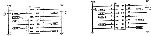
图9表示图8所示检测单元内部部件的电气方框图;Figure 9 represents an electrical block diagram of the internal components of the detection unit shown in Figure 8;
图9A表示并行连接的线性阵列计时图,它表示与图8和9中检测单元有关的脉冲;Figure 9A shows a parallel connected linear array timing diagram showing the pulses associated with the detection elements in Figures 8 and 9;
图10表示图1实施例中所用的在第一代电子线路中使用的电路图;Fig. 10 represents the circuit diagram used in the first generation electronic circuit used in Fig. 1 embodiment;
图10A表示在图1和2实施例中所用的时钟信号发生电路的方框图;Fig. 10A represents the block diagram of the clock signal generating circuit used in Fig. 1 and 2 embodiment;
图10B表示“power-on”电路;Figure 10B shows a "power-on" circuit;
图11是激光电源的电路图;Fig. 11 is the circuit diagram of laser power supply;
图11A表示图1和2装置中所用的Y-Z检测器阵列的输出接口;Figure 11A shows the output interface of the Y-Z detector array used in the apparatus of Figures 1 and 2;
图11B解释象素布局的图形;Fig. 11B is a diagram explaining pixel layout;
图11C表示用于模-数转换的三个电平转换器;Figure 11C shows three level shifters for analog-to-digital conversion;
图12表示在图1和2的实施例中所用的计数器电路方框图;Fig. 12 represents the counter circuit block diagram used in the embodiment of Fig. 1 and 2;
图12A表示两个门电路;Figure 12A shows two gate circuits;
图12B表示两个缓冲器接口电路方框图;Figure 12B shows a block diagram of two buffer interface circuits;
图12C表示在图1和2实施例中所用的主控制电路方框图;Fig. 12 C represents the main control circuit block diagram used in Fig. 1 and 2 embodiment;
图12D表示两个静态存储器RAM电路;Figure 12D shows two static memory RAM circuits;
图12E表示快速存储器EEPROM电路;Figure 12E shows the flash memory EEPROM circuit;
图12F表示LCD驱动器、转换和光电晶体管驱动器;Figure 12F shows the LCD driver, switch and phototransistor driver;
图12G表示转换PIN驱动器和PIN光电传感器;Fig. 12G shows switching PIN driver and PIN photoelectric sensor;
图12H和12I表示在实施例电路中可用的印刷电路板;Figures 12H and 12I represent printed circuit boards usable in embodiment circuits;
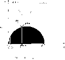
图13是本发明实施例中执行的用于计算一种算法功能的用xy轴表示的图形;Fig. 13 is a graph represented by an xy axis for calculating an algorithm function implemented in an embodiment of the present invention;
图13A描述了一个根据硬币边缘凹槽特征来识别硬币的实施例;Figure 13A depicts an embodiment of coin identification based on coin edge groove features;
图14表示本发明与电气有关的部件实施例方框图;Fig. 14 represents a block diagram of an embodiment of the present invention's electrical components;
这些图形只用于描述目的,因此没有必要按比例绘制。The figures are for descriptive purposes only and are not necessarily drawn to scale.
在实施例中,为了说明,相应的部件用相同是数字标号表示。例如,在每个实施例中激光辐射源将用相同的参考标号,但这并不意味着实施例是相同的。In the embodiments, corresponding components are denoted by the same numerals for the sake of explanation. For example, a source of laser radiation will be given the same reference numeral in each embodiment, but this does not mean that the embodiments are identical.
具体实施方式Detailed ways
第一个实施例The first embodiment
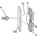
参考图1,用硬币检测装置20来描述本发明的第一个实施例。装置20包括壳体5。Referring to FIG. 1, a
具有圆柱形激光单元1的激光源可滑动地安装在壳体5的圆柱孔内。A laser source with a
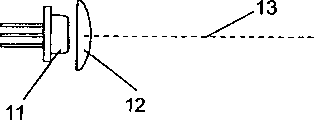
激光单元1包括一个传统的激光二极管11和透镜组(两个组都用数字12表示)。激光二极管11产生一个激光束13(在图1中用点划线表示)。透镜组12被设计用来将激光束13转变成这样的一种光束当它离开激光单元1的前部时光束成扇形。激光束作为一种点光源从激光二极管11中释放出来,通过透镜12散发成扇形形状以便光束能够被用来同时照射硬币的较大部分。The
激光束13的形状是以扇形激光束形式散发的形状。为了产生扁平散发的激光束,运用两套不同特性的透镜。第一组透镜12对完全与轴平行的具有矩形截面的激光束起作用。另一组圆柱形透镜12使激光束的截面变长以便此截面变成一个细长的矩形,几乎成为一条直线的点。从激光二极管11发出的激光束13通过这些透镜。在图1中,使用激光单元1中的透镜12,通过在孔51中可滑动地调整激光单元1的位置来对扇形激光束进行聚焦。The shape of the
硬币检测装置20进一步包括硬币导向机构,该导向机构包括一个具有下边框62和上部通道52的通道61,在通道61中,示出了硬币4。硬币经由硬币插入孔63(最好见图1D)被引入到通道52中。通道61沿通道引导硬币4。硬币通道52横向延伸于壳体单元5。硬币4在它的周边上被硬币导向机构的下边框62所继续支持。硬币4在垂直于图1平面的方向上通过本装置。The
从激光源11起在通道61的较远侧,壳体5包含有一个以传感器阵列单元3的形式存在的激光检测器。阵列单元3包括许多一个挨一个地各自高速充电的蓄电池和象素(没有分别表示),这些充电蓄电池包括对激光辐射敏感并且能检测和测量激光辐射能量级别的象素。象素以线性阵列排列,在线性或格状方位上形成邻近的象素阵列。每一个在非充电状态下的充电蓄电池在激光束13照射在特别的象素上时都能变成充电状态。对于检测作为激光束基本元素的光子来说,象素是足够敏感的。传感器阵列3也包括适用于将传感器阵列单元3同以后描述的电子线路相连的插头19。On the far side of the
由激光二极管11产生的激光束13直射到传感器阵列单元3上。在图1的实施例中,激光束离开二极管11后,激光束13被直射以形成扇形扁平形状。扇形标准指的是当激光束离开二极管后激光束散射。扁平束标准指的是激光束辐射的细线或细长条形平面的形状。辐射的扇形平面一般直射到线性阵列的中央。The
激光束13在激光二极管11和传感器3的线性阵列之间通过。激光束13沿着孔51在轴线上直射且扫过通道52。激光束13的轴线基本上与在通道中硬币的主平面垂直。激光束13直射在要被检测的硬币4的表面。硬币4拦截在激光二极管11与传感器阵列单元之间通过的激光束的一部分。在本实施例中,激光束是静止的,硬币移过激光束。当圆形硬币移过激光束时,它是旋转的,而非圆形或多边形硬币将滑过光束。A
由于被激光束照射的那些象素将引起充电蓄电池充电,而被硬币遮挡的那些象素将不会引起充电蓄电池充电,传感器阵列3能检测硬币拦截激光的位置及不被硬币拦截激光的位置。被充电和不被充电蓄电池的信息被用来获得硬币表面如下所描述的特性指示。Since those pixels illuminated by the laser beam will cause the rechargeable battery to charge, while those pixels covered by the coin will not cause the rechargeable battery to charge, the
参考图9,象素和充电蓄电池基于通过测量激光束是最小和最大可吸收的量子能量的饱和度来工作。当一个象素被激活到它的最大饱和充电量的大约一半的等级时,象素的控制逻辑能够确定被象素接受的来自于激光束能量的精确量。然后控制逻辑决定是否将充电的蓄电池当做不充电状态的“0”还是当做充电状态的“1”。Referring to Figure 9, the pixels and rechargeable batteries operate based on the saturation of the quantum energy that is the minimum and maximum absorbable by measuring the laser beam. When a pixel is activated to a level of approximately one-half of its maximum saturation charge, the pixel's control logic can determine the precise amount of energy received by the pixel from the laser beam. The control logic then decides whether to treat the charged battery as a "0" for an uncharged state or a "1" for a charged state.
在本实施例中,线性传感器阵列单元3的平面基本上在通道52中平行于硬币4的主平面延伸,并且同沿着通道硬币通过的方向相垂直。在图1中,阵列3的下端距下边框62相隔第一距离d,第一距离d小于装置所使用的任何硬币的最小直径。阵列3的上端距下边框62相隔第二距离D,第二距离D大于任何硬币的最大直径。当硬币沿着通道通过时,激光束13将因此被硬币4的上部区域所遮挡。In this embodiment, the plane of the linear
最好用激光束13遮挡硬币4的上部分区域以使硬币上部区域得到测量。另外,硬币4的其它区域也可以被测量,如侧边部分。然而,当硬币与硬币导向机构的下边框62接触时,这样的接触使对与下边框62相接触的硬币的那些部分的精确测量变得困难。Preferably, the upper area of the
硬币的测量不须考虑整个直径或(在不规则硬币的情况下)最大截面。通过回避直径或最大截面的读数,与测量硬币接触的滚动表面那部分相关的问题被减到最小。Coins are measured without regard to the entire diameter or (in the case of irregular coins) the largest cross-section. By avoiding the reading of diameter or maximum cross-section, problems associated with measuring that part of the rolling surface that the coin contacts are minimized.
线性阵列3的传感器单元,在各自的连续采样时间上产生电输出,这些输出根据硬币所阻拦的象素数及没有被硬币阻拦的象素数来确定。如下面将要详细描述的那样,当硬币移过线性阵列3时,最好多次采样这个信号。The sensor elements of the
线性阵列3的传感器单元与处理识别有关硬币的那些输出以信号处理器相连。信号处理器是图12C和14所示的微控制器14的形式。微控制器14包括用于确定多个约定参考数据记录中的哪一个(如果是任意的话)与被处理的输出相对应的比较装置。例如,来自于线性阵列3所处理的输出与已知的大量硬币的数据记录相比较。通过将从线性传感器中获得的已被处理的输出与已知硬币的相应数据记录相对照,来识别硬币4。The sensor units of the
壳体单元5是由具有较好吸收散射激光辐射的材料制造的,如黑色的聚碳酸脂。壳体5的外部状况在图1C和1D中进行了描述。其它设计可以根据它们所安装的特别环境来选择。另外,在本发明的其它实施例中,除了安装在自已壳体中的硬币检测装置外,将硬币检测装置中的各个部件整体制造成装置的一部分也是可能的,例如该装置被用在自动售货机或电话机。在这些实施例中,硬币导向机构作为特别装置部件中的一个零件。可以设想,硬币导向机构可以不是一个分立的可识部件。在这样的实施例中,在整个装置中可以将用于对激光束拦截的硬币的导向机构任何特征看成是实现硬币导向的功能。The
在其它的实施例中,硬币检测装置的各种结构部件可以被铸造成部件。例如,镜子和棱镜可以用与壳体和硬币导向机构一样的材料铸成。作为制造的方法,铸造的优点是用于减少装置的成本。In other embodiments, various structural components of the coin detection device may be cast as components. For example, mirrors and prisms can be cast from the same material as the housing and coin guide. As a method of manufacture, casting has the advantage of reducing the cost of the device.
图7表示用于构造透镜组的另一个实施例。激光束13所期望的形状是运用平行光透镜75和产生线光透镜72来产生的,从激光二极管产生的激光束通过这些透镜。通过运用在激光单元1中的第二系列透镜12以及通过调整在孔51中激光单元1的轴线位置来聚焦扇形光束。通过旋转前面的传感器组件73,如图7所描述的,光束被聚焦且与轴平行。锁环74用来固定最后的位置。为了在线性阵列3上产生激光束13最好的入射线,透镜系统可以通过运用激光二极管模板提供的一个键来旋转。操作距离越大,光线就越长且越粗。Fig. 7 shows another embodiment for constructing a lens group. The desired shape of the
第二个实施例The second embodiment
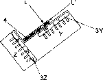
图2、2A和2B描述了本发明的第二个实施例。除了激光检测器包括两个线性阵列3Y、3Z外,第二个实施例与第一个实施例相似。(为了这里描述概念方便起见,X和Y指的是在工程中应用的正交x和y轴术语。)Figures 2, 2A and 2B depict a second embodiment of the invention. The second embodiment is similar to the first embodiment except that the laser detector comprises two
激光束13从激光二极管11发出,被透镜12a折射,并进一步被透镜12b折射。
利用“Powell透镜”获得激光束聚焦成一线。通过Powell透镜聚焦的激光辐射线沿着该线的整个长度具有一致的密度特性。图7描述了激光束的发散效果。图7A表示利用Powell透镜12来加宽激光束13的角度。图7B是图7A所示激光束的俯视图。图7A描述的通过Powell透镜形成的激光束是一种薄板状的激光辐射。The "Powell lens" is used to focus the laser beam into a line. A line of laser radiation focused by a Powell lens has a consistent density profile along the entire length of the line. Figure 7 depicts the divergence effect of the laser beam. FIG. 7A shows the use of a
激光束达到与硬币4的交汇点时,激光束沿着一个路径基本垂直直射在硬币4的主平面。激光束的一部分直射在硬币4的边缘并且被硬币4的周围边界或边缘所阻挡。激光束的其余部分照射在线性阵列3Y上。因此,线性阵列3Y能够确定硬币4的边缘特征和/或厚度。图2C描述了硬币滚过线性阵列3Y、3Z的侧视图。When the laser beam reaches the point of intersection with the
同时,通过棱镜12C改变激光束一部分的方向。镜子可以用来取代棱镜。棱镜12c使光束垂直偏转以便光束照射在硬币的边缘。向下直射光束的仅仅一部分照射在其它线性阵列3Z上。因此,使用两个线性阵列来检测硬币4的边缘或表面不同的部分。At the same time, the direction of a part of the laser beam is changed by the prism 12C. Mirrors can be used instead of prisms. The
在硬币和光束的关键交汇点上,完全或至少基本垂直于硬币主平面光束的优点是光束因此直接照射在线性传感器上而没有任何进一步的偏移。因而,线性传感器的测量将是实际硬币的精确测量。The advantage of being completely or at least substantially perpendicular to the main plane of the coin at the critical intersection of the coin and the beam has the advantage that the beam thus impinges directly on the linear sensor without any further deflection. Thus, the measurement of the linear sensor will be an accurate measurement of the actual coin.
对比起来,在图4中,如果激光束以一锐角截取硬币,线性传感器的测量将比硬币的实际尺寸稍大。然而,只要在计算已知硬币的数据度量时考虑了这个因素,硬币检测装置仍然能有效地工作。因此,在广义上对本发明最好但不是必需,在截取的重要点上光线完全与硬币主平面垂直。In contrast, in Figure 4, if the laser beam intercepts the coin at an acute angle, the linear sensor's measurement will be slightly larger than the actual size of the coin. However, as long as this factor is taken into account when calculating the data metrics for known coins, the coin detection device will still work effectively. Therefore, it is preferable but not necessary for the invention in a broad sense that the rays be completely normal to the principal plane of the coin at the important point of the intercept.
然而,在截取点上,硬币和激光束垂直的优点是利用垂直光束可以考虑硬币边缘凹槽产生的偏差。显然如果光束基本上以锐角截取硬币的边缘,光束将会遮住凹槽的起伏。锐角的光束将只与没有凹槽或凸条的周边相遇。However, at the point of interception, the coin and laser beam have the advantage that with a perpendicular beam, deviations from coin edge grooves can be taken into account. Obviously if the beam intercepts the edge of the coin substantially at an acute angle, the beam will obscure the undulations of the groove. A sharply angled beam will only meet the perimeter with no grooves or ridges.
在图2的第二个实施例中,直射在硬币表面的第一个激光束以及直射在硬币边缘的第二个激光束都是由一个激光二极管11中发出的同一光束中获得的。第二激光束是通过一个使第一激光束的一部分偏转的棱镜由第一激光束中获得的。然而,在本发明的其它实施例中,独立的激光源可以产生独立的激光束。可以使用多个激光二极管。In the second embodiment of FIG. 2, the first laser beam directed at the surface of the coin and the second laser beam directed at the edge of the coin are obtained from the same beam emitted by a
最好本装置的硬币导向机构在使用中被这样安装以便硬币导向机构倾斜。图2D描述了硬币导向机构的倾斜方位。硬币导向机构的倾斜角减少了硬币沿着导向机构移动时硬币摆动的危险。在硬币竖立沿着导向机构移动时,会有摆动的危险。本装置辨识几微米数量级尺寸的能力意味着在硬币导向机构内硬币的任何小误差都将影响本装置的精确性。确保稳定程度的一个方法是在硬币通过线性阵列前使硬币停止,然后释放硬币,允许它继续通过线性阵列。Preferably the coin guide of the device is mounted in use such that the coin guide is inclined. Figure 2D depicts the tilted orientation of the coin guide mechanism. The angle of inclination of the coin guide reduces the risk of the coin wiggling as it travels along the guide. There is a risk of swinging coins as they move upright along the guide. The ability of the device to discriminate dimensions on the order of a few microns means that any small error in the coin within the coin guide mechanism will affect the accuracy of the device. One way to ensure a degree of stability is to stop the coin before it passes through the linear array, and then release the coin to allow it to continue through the linear array.
第三个实施例一自由下落实施例The third embodiment-free fall embodiment
本发明可以包括硬币不需由硬币导向机构继续支撑的实施例。例如,硬币导向机构可以仅与硬币接触到硬币截取激光束前的那一点为止。在拦截激光束的瞬间,硬币实际上可以自由下落。最好,在硬币通过自由空间的下落中,在硬币释放它原来的方位前,硬币与激光束垂直。在自由下落中可以测量硬币边缘或表面的任一部分。与不用激光辐射的系统比较,使用激光可以足够快地对硬币进行测量,以致当硬币处在自由下落中,也可以对硬币进行测量。The present invention may include embodiments in which the coin need not be continuously supported by the coin guide mechanism. For example, the coin guide may only be in contact with the coin up to the point before the coin intercepts the laser beam. The moment the laser beam is intercepted, the coin can actually fall freely. Preferably, during the coin's fall through free space, the coin is perpendicular to the laser beam before the coin releases its original orientation. Any part of the coin's edge or surface can be measured in free fall. Compared to systems without laser radiation, the laser can be used to measure the coin fast enough that it is also possible to measure the coin while it is in free fall.
图4描述了第三个实施例,在该实施例中,随着硬币的自由下落,硬币截取激光束。在该实施例中,使用一个长的线性传感器3。当硬币下落通过传感器阵列3时,用长传感器阵列测量整个面积和直径。在第三个实施例中选择透镜来提供一个宽的扇形范围。激光束宽角度及长线性传感器结合在一起能够在硬币通过较长距离内对硬币进行测量。由于自由下落的硬币比在硬币导向机构中滚动的硬币通过得更快,这特别有用。激光束13以锐角照射在硬币的上边缘,可以进行与硬币前部表面有关的测量。如上所述,该锐角意味着测量必需考虑光束的发散。Figure 4 depicts a third embodiment in which the coin intercepts the laser beam as it falls freely. In this embodiment, one long
其它的实施例Other embodiments
本发明不限于具有垂直于硬币主平面的激光源和激光检测器的装置。The invention is not limited to devices having a laser source and a laser detector perpendicular to the main plane of the coin.
在如图5和6所示的另外的实施例中,镜子和/或棱镜用于使激光束13偏转。在这些另外的布局中,激光束还能用垂直的方式与硬币表面垂直。In further embodiments as shown in FIGS. 5 and 6 , mirrors and/or prisms are used to deflect the
在某些实施例中,可以使用光纤将激光辐射传送到激光检测器。光纤可以被用来引导沿通道的激光辐射,该通道能够需要透镜和/或棱镜的复杂布局。有选择地使用镜子、棱镜和/或光纤来使激光束偏转可以使硬币检测装置设计得小巧。In some embodiments, an optical fiber may be used to deliver the laser radiation to the laser detector. Optical fibers may be used to guide the laser radiation along channels which can require complex arrangements of lenses and/or prisms. Selective use of mirrors, prisms and/or optical fibers to deflect the laser beam allows for a compact coin detection device design.
激光Laser
激光辐射源,如激光二极管,特别适用于这样的硬币检验装置,因为激光是一个相干的强方向性的辐射源。任何其它非激光辐射和光线都是不相干的。激光的独特性是由一个已知受激辐射发射过程引起的,而普通光源是由自发发射引起的。激光辐射起因于在单一量子状态中受约束的光子束和原子受激发射。Laser radiation sources, such as laser diodes, are particularly suitable for use in such coin verification devices, since laser light is a coherent, strongly directional radiation source. Any other non-laser radiation and light are irrelevant. The uniqueness of laser light is caused by a process known as stimulated emission of radiation, whereas ordinary light sources are caused by spontaneous emission. Laser radiation results from a confined beam of photons and stimulated emission of atoms in a single quantum state.
由于这样光源的工作寿命长,因此激光也是特别适合的。(当前激光源的典型值是10,000到80,000小时,1到9年。激光二极管其它寿命估价为500,000小时)。Lasers are also particularly suitable due to the long operating life of such light sources. (Typical values for current laser sources are 10,000 to 80,000 hours, 1 to 9 years. Other life estimates for laser diodes are 500,000 hours).
本发明实施例装置可以使用为原有设备制造商的使用所设计的各种激光二极管系统,它们的输出功率根据BS(EN)60825设定。在结合在上述装置中时,可能必须增加附加的安全特征以确保装置完全遵循该标准。然而,在广义上讲,本发明并不严格限制包括这样的安全特征。Devices according to embodiments of the present invention may use various laser diode systems designed for original equipment manufacturer use, with their output power set in accordance with BS (EN) 60825. When incorporated in such devices, additional safety features may have to be added to ensure that the device fully complies with the standard. However, the invention in its broadest sense is not strictly limited to including such security features.
激光二极管输出的激光束面积,在本发明的实际实施例中是(高x宽)2.5mm×1mm,达到线性阵列3的扩展面积是30.0mm×1.2mm.The area of the laser beam output by the laser diode is (height x width) 2.5mm × 1mm in the actual embodiment of the present invention, and the extended area reaching the
激光单元由一个正电压操作,在5到6v范围的非稳压电源内运行。然而,最好用较低的电压,由于较低热量的产生有利于延长装置的期望寿命。如图11所示,用+/-5%内调节的4.5v电源这样的环境来驱动激光单元。激光模块外壳最好与电源电压绝缘。The laser unit is operated from a positive voltage, running from an unregulated power supply in the 5 to 6v range. However, lower voltages are preferred, since lower heat generation is beneficial for extending the expected lifetime of the device. As shown in Figure 11, the laser unit was driven with such an environment as a regulated 4.5v supply within +/- 5%. The laser module housing is preferably insulated from the supply voltage.
本发明的实际实施例使用了一个激光二极管11,该二极管根据传感器单元3的正常响应产生具有由635nm到840nm范围波长的激光辐射。选择激光辐射波长使传感器单元3的响应最大,以便提高装置的性能。然而,本发明并不限于使用激光辐射的特别波长,激光源的范围可以使用例如由330nm到1500nm,这个范围覆盖了从接近UV到接近红外线的光谱区域。The practical embodiment of the invention uses a
在用负电压操作的激光模块上可以获得TTL失效的功能。作用在TTL失效输入端+4v和+7之间的输入关闭激光,0v的输入将接通激光。如果这个输入端不用,则它可以悬空。使用这个输入端,可以在10Hz或更高频率下脉冲式开或关激光。然而,在上述的实际实施例中,激光二极管的连续式激发是最优的,因为这样将给二极管更长的使用寿命。TTL deactivation is available on laser modules operated with negative voltages. An input applied between +4v and +7 on the TTL fail input turns off the laser, and an input of 0v turns the laser on. If this input is not used, it can be left open. Using this input, the laser can be pulsed on or off at frequencies of 10 Hz or higher. However, in the practical embodiment described above, continuous excitation of the laser diode is optimal, as this will give the diode a longer lifetime.
在上述实际实施例中激光在高于最小电压的电压下和/或在环境温度大于60℃温度以上的情况下运行时,应当使用一个附加的散热器。如果激光二极管的箱体温度超过它的最大规定时,将出现过早或灾难性的失败。为了有助于激光模块的散热,激光单元1最好具有一个容纳激光二极管和用于聚焦光束透镜An additional heat sink should be used when the laser is operated at voltages higher than the minimum voltage and/or at ambient temperatures above 60° C. in the above practical embodiments. If the case temperature of a laser diode exceeds its maximum specification, premature or catastrophic failure will occur. In order to contribute to the heat dissipation of the laser module, the
(如图1)的圆柱形箱体。这个箱体由PMMA(聚甲基丙烯酸脂)制造,也可以用诸如铅这样的其它材料制成。(as shown in Figure 1) of the cylindrical box. The case is made of PMMA (polymethacrylate), but other materials such as lead are also available.
线性传感器阵列Linear Sensor Array
在列举的实施例中所用的激光检测器具有线性传感器阵列单元3的形式。在图8中,传感器阵列单元3具有如图8和9所示保持的产品集成传感器CMOS过程线性传感器阵列。这样的传感器包括一个具有256×1象素阵列传感器(每个为63.5μm×55μm象素之间的间隔为8.5μm)的线性阵列,每个阵列根据有关象素接受的激光辐射量产生信号。然而,本发明的其它实施例可以更有利地集合具有更大数量象素传感器的线性阵列。例如,更大数量的象素传感器将在硬币测量过程中获得更多的信息。因此信息量的增加将提高测量精度,特别是在后面将要描述的要求综合或累计度量的那些实施例中。The laser detector used in the illustrated embodiment has the form of a linear
显然,象素被组合得越小越密,硬币识别结果的正确性就越大。Obviously, the smaller and denser the pixels are combined, the greater the correctness of the coin recognition result.
阵列形成于两个128个象素的两个平行连接的阵列,如图9所示。通过包括开关控制逻辑、充电蓄电池和调整来自于象素数据链的输出放大器的128位移位寄存器来控制128个象素中的每一个。The array is formed from two parallel connected arrays of 128 pixels, as shown in FIG. 9 . Each of the 128 pixels is controlled by a 128-bit shift register including switch control logic, charging the battery and adjusting the output amplifier from the pixel data chain.
如下面所要描述的,在每一个通过脉冲式输入SI确定的采样周期中,各个象素的输出以数字脉冲串的形式通过插头4和8(AO1和AO2)传送。正如图9所示,传感器阵列单元3有时钟输出CLK,外部触发脉冲输入SI1和SI2,输出AO1(象素1-128)和AO2(象素129-256)。另外阵列的连接可以是串联的。As will be described below, in each sampling period determined by the pulsed input SI, the output of each pixel is transmitted through the
在图8中,256个传感器元件的阵列81提供256个不同的象素。照射象素的激光辐射能在象素下面的区域内产生电子空穴对。当这些空穴对扫进感光层时,象素上由偏流产生的区域引起电子在这个元素上聚积。在每个元素上所聚积的电荷量与入射激光辐射量和采样周期成正比。In Figure 8, an array 81 of 256 sensor elements provides 256 different pixels. Laser radiation striking a pixel can generate electron-hole pairs in the region beneath the pixel. As these hole pairs sweep into the photosensitive layer, the region on the pixel created by the bias current causes electrons to accumulate on this element. The amount of charge accumulated on each element is proportional to the amount of incident laser radiation and the sampling period.
运用激光辐射是本发明的一个重要特征。没有使用激光辐射的早期装置不会获得本发明的全部优点。象素是63.5μm×55μm,中心距离是63.5μm。每个象素由8.5μm的距离分开。由于使用激光辐射,系统能检测以大约±1象素即大约63.5μm为一级的硬币尺寸的变化。这是因为激光辐射具有单一波长,当与同光学光线结合起来的光散射相比较时,激光具有最小的散射。激光的这种特性能使硬币尺寸的极小差别得以识别。在当前实施例中激光辐射源的波长是具有入=670nm的波长,而本发明并不限于激光辐射的特别波长。因此,使用本发明实施例的装置可以识别硬币间小到一个象素即63.5μm或0.0635mm的差别。The use of laser radiation is an important feature of the present invention. Early devices that did not use laser radiation would not have achieved the full benefits of the present invention. The pixel size is 63.5 µm x 55 µm, and the center-to-center distance is 63.5 µm. Each pixel is separated by a distance of 8.5 μm. As a result of the use of laser radiation, the system is able to detect changes in coin size in the order of about ±1 pixel or about 63.5 µm. This is because laser radiation has a single wavelength and laser light has minimal scatter when compared to light scatter in combination with optical light. This property of the laser enables very small differences in coin size to be identified. The wavelength of the laser radiation source in the present embodiment is a wavelength with λ = 670 nm, while the invention is not limited to a particular wavelength of laser radiation. Therefore, using the apparatus of the embodiment of the present invention, it is possible to identify differences between coins as small as one pixel, ie, 63.5 μm or 0.0635 mm.
幸而,在几种流通硬币直径仅有一个象素差别的情况下,这些硬币的厚度基本上也不相同。例如美国和加拿大一分的硬币实际上每一个直径都相同,但在厚度上每个大约有160μm或0.16mm之差。因此,即使美国和加拿大一分硬币的直径只有一个象素之差,也可以根据它们厚度上的差别来识别这些硬币。然而,当接受有限数量的硬币时,硬币的测量可以根据尺寸的度量来进行,其中在硬币之间这样多种硬币的差别是显著的。Fortunately, while several circulating coins differ by only one pixel in diameter, the coins also differ substantially in thickness. For example, the American and Canadian one-cent coins are actually each the same diameter, but each has a difference of about 160 μm or 0.16 mm in thickness. Thus, even if the diameter of a U.S. and Canadian penny differs by only one pixel, the difference in thickness can be used to identify the coins. However, when a limited number of coins are accepted, measurements of coins may be made in terms of size measures where such a variety of coin differences are significant between coins.
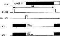
如图9A所示,256×1阵列传感器的操作特征有两个时间周期:积分周期tint(前面所示的采样周期),在这个周期内,通过偏流,在象素中产生电荷,以及输出周期tint,在这个周期内,由公共输出AO1和AO2传送一个采样周期的数字输出信号链。积分周期由作用到单元3接口2(SI1)和接口10(SI2)的两个连续控制脉冲之间的间隔时间tint来定义。积分周期所需的时间长度依据入射激光辐射量和所期望的输出信号等级而定。As shown in Figure 9A, the operation of a 256×1 array sensor is characterized by two time periods: the integration period t int (the sampling period shown earlier), during which charges are generated in the pixels by the bias current, and the output Period t int , during which the digital output signal chain for one sampling period is delivered by the common outputs AO1 and AO2. The integration period is defined by the interval time t int between two consecutive control pulses applied to
在该实施例中,传感器有256个排列成线性阵列的象素组成。由于激光辐射能照射在每个象素上,产生光电流。然后通过与那个象素有关的快速积分电路对这个电流进行积分。In this embodiment, the sensor consists of 256 pixels arranged in a linear array. As laser radiation can impinge on each pixel, a photocurrent is generated. This current is then integrated by a fast integrating circuit associated with that pixel.
在积分周期内,采样电容通过一个模拟量开关与积分器的输入相连。每个象素上电荷的聚积量与该象素上的激光能量和积分时间成正比。During the integration period, the sampling capacitor is connected to the input of the integrator through an analog switch. The amount of charge accumulation on each pixel is proportional to the laser energy and integration time on that pixel.
在图11A中,由256-位移位寄存器和复位逻辑来控制积分器的输出和复位。输出周期由SI1(接口2)和SI2(接口10)上的逻辑电路计时来开始。另一个被称为保持的信号产生于SI1和SI2的上升沿并且同时被传送到部分1和2。这使得所有256个采样电容从它们的积分器中断开,开始一个积分复位周期。由于SI脉冲通过移位寄存器计数时,存储在采样电容上的电荷顺序地与在模拟量输出口AO产生电压的电荷-耦合输出放大器相连。在SI脉冲输入后,积分器复位周期结束18个时钟周期。然后开始下一个积分周期。在第128个时钟上升沿到来时,记录下在SO1接口13(部分1)SO1脉冲时间。在第129个时钟周期的上升沿到来时终止SO1脉冲,使部分1的模拟量输出AO1回到高阻态。类似地,在第256个时钟脉冲记下SO2的时间。需要在第257个时钟脉冲终止SO2,使AO2回到高阻态。In FIG. 11A, the output and reset of the integrator is controlled by a 256-bit shift register and reset logic. The output cycle is clocked by the logic on SI1 (Interface 2) and SI2 (Interface 10). Another signal called hold is generated on rising edges of SI1 and SI2 and is transmitted to
由需要外部下拉电阻的有源输出放大器来驱动AO。当输出不在输出状态时,它在高阻态。输出通常为0v代表没有任何功率输入,2v为标准满量程输出。AO is driven by an active output amplifier that requires an external pull-down resistor. When the output is not in the output state, it is in the high-impedance state. The output is usually 0v for no power input and 2v for standard full scale output.
在进一步的实施例中,激光检测器可以包括许多以矩阵方位排列的线性传感器阵列。使用这样矩阵传感器的优点在于激光检测器具有更大的表面积。In a further embodiment, the laser detector may comprise a number of linear sensor arrays arranged in a matrix orientation. An advantage of using such a matrix sensor is that the laser detector has a larger surface area.
第一代电子线路
能够由图10所示的任何计时电路产生时钟信号CLK和控制信号S1,其中555计时电路101产生时钟信号CLK,而8位计数器74LS590和史密特触发器(Schmitt-trigger)74LS221(参考电路102)产生控制信号。The clock signal CLK and the control signal S1 can be generated by any timing circuit shown in FIG. ) to generate a control signal.
传感器阵列单元3将输出数字脉冲链传送到图10所示的计数器电路,该计数器电路包括串联在一起的3个4位计数器74LS160以成为单个的12位计数器92。该计数器92接受来自与门91的信号,该与门将时钟信号CLK和传感器单元3的数字串行输出信号连在一起。由于每个可能具有值“1”或“0”的充电蓄电池信号是由线性阵列单元3中的象素产生的,因此,由时钟信号CLK将充电蓄电池信号计时在计数器的输入端。等于“1”的充电蓄电池信号使计数器向上计数。The
当通过传感器单元3传送所有与传感器矩阵单元3中的256个检测象素有关的256位时,由传感器阵列单元3发出的信号SO2触发一套门电路93、74LS373以便256个象素的计数结果被锁在输出端。然后这些输出通过如图数字94所示的7段显示驱动器74LS48进行译码以产生在7段LED显示器95上的3位数。这个数值与有关硬币具体被检测的区域相对应。When all 256 bits related to the 256 detection pixels in the
传感器阵列单元3的输出作为输入也能作用到主控制比较电路上(图14),该主控比较电路将该输出同存储在数据库16中并与装置准备识别硬币数量相对应的预定参考值相比较。数据库呈快速RAM的形式。呈EEPROM形式的比较电路15在图14中进行了描述。比较电路提供识别被检测硬币的输出信号SC。The output of the
第二代电子线路
下面描述在本发明实施例中所用的第二代电子线路,第二代电子线路是通过进一步的研究和开发所获得的。The second-generation electronic circuits used in the embodiments of the present invention, which were obtained through further research and development, are described below.
Y-传感器阵列:Y-sensor array:
参考图2D,传感器直接测量硬币4的面积、半径和直径。它可以检测和计数硬币边缘出现的凹槽和凸条。Referring to FIG. 2D , the sensor directly measures the area, radius and diameter of the
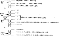
传感器阵列由两个较小阵列YH和YL组成。每一个由128个象素组成。这些象素的布置在图11b中以图解的形式进行了解释。在每次扫描中,电子线路将产生被如下定义的数字Y:如果(被暴光的象素数)=0,让Y=0,否则Y=(暴光的象素数)-1。The sensor array consists of two smaller arrays YH and YL. Each consists of 128 pixels. The arrangement of these pixels is explained diagrammatically in Figure 11b. In each scan, the electronics will generate a number Y defined as follows: If (number of pixels exposed)=0, let Y=0, else Y=(number of pixels exposed)-1.
以2MHz的时钟频率运行时,传感器能够在64.5ns内输出每个阵列的所有128个象素。因此,最大可能扫描率为每秒15503次扫描或每秒4百万次数字“0”或“1”。如果硬币以1米/秒通过阵列时,那么硬币的每1mm大约被扫描16次。当硬币通过阵列时,这足够用于确定Y的最小值。Y的最小值与硬币的直径对应。在每次扫描中,由U204产生的SI脉冲将激发在YL和YH中每个象素的移出循环。U301将开始计算YL和YH中的“高”象素数。暴露在激光L中的象素将提供“高”输出,而被硬币覆盖或没有暴露在激光中的象素将提供“低”输出。只要遇到第一个“低”象素,U301就停止计数。When running at a clock frequency of 2MHz, the sensor can output all 128 pixels of each array in 64.5ns. Thus, the maximum possible scan rate is 15503 scans per second or 4 million digital "0"s or "1"s per second. If a coin passes through the array at 1 m/s, then every 1 mm of the coin is scanned about 16 times. This is sufficient for determining the minimum value of Y as the coin passes through the array. The minimum value of Y corresponds to the diameter of the coin. In each scan, the SI pulse generated by U204 will activate a shift-out cycle for each pixel in YL and YH. U301 will start counting the number of "high" pixels in YL and YH. Pixels exposed to the laser light L will provide a "high" output, while pixels covered by coins or not exposed to the laser light will provide a "low" output. As soon as the first "low" pixel is encountered, U301 stops counting.
如果硬币覆盖超过了YH阵列,那么,YH的第一个象素是“低”。Y的值小于128,即Y7=0。U301将只计数YL阵列中的“高”象素。If the coin covers more than the YH array, then the first pixel of YH is "low". The value of Y is less than 128, that is, Y7=0. U301 will only count the "high" pixels in the YL array.
如果硬币覆盖没有超过YH阵列,那么YH的第一个象素为“高”。YL所有象素将被暴光,因此Y将大于127,即Y7=1.If the coin cover does not exceed the YH array, then the first pixel of YH is "high". All pixels of YL will be exposed, so Y will be greater than 127, that is, Y7=1.
U301将只计数在YH阵列中的“高”象素。在移出循环末端,U301和Y7的计数值将被锁存到U205中作为Y值且由PC或微处理器顺序读取。U301 will only count the "high" pixels in the YH array. At the end of the shift out cycle, the count values of U301 and Y7 will be latched into U205 as the Y value and read sequentially by the PC or microprocessor.
第一个到Y-传感器阵列的SI脉冲由两个上电(power-up)复位脉冲PUR1和PUR2所产生,以启动第一移位循环(shift-out cycle)。在该移位循环结束时,传感器阵列产生用于从新生成SI脉冲的SO脉冲,这样传感器以其最大速率不确定地扫描和移出数据。The first SI pulse to the Y-sensor array is generated by two power-up reset pulses PUR1 and PUR2 to start the first shift-out cycle. At the end of this shift cycle, the sensor array generates SO pulses to regenerate SI pulses so that the sensor scans and shifts out data indefinitely at its maximum rate.
Z-传感器阵列Z-sensor array
这个传感器阵列直接测量硬币的厚度。仅有阵列的第一半(ZL)被使用。This sensor array directly measures the thickness of the coin. Only the first half (ZL) of the array is used.
参考图2E,窗口W打开允许ZL阵列的一定数量的象素暴露在激光L中。当硬币通过窗口时,由硬币阻挡的象素数量与硬币的厚度成正比。已知象素之间的中心距离,能够计算硬币的实际厚度。Referring to FIG. 2E, the window W is opened to allow a certain number of pixels of the ZL array to be exposed to the laser light L. Referring to FIG. When a coin passes through the window, the number of pixels blocked by the coin is proportional to the thickness of the coin. Knowing the center distance between pixels, the actual thickness of the coin can be calculated.
Z-传感器阵列与Y传感器阵列并联工作,共享同一2MHz时钟和SI脉冲。The Z-sensor array works in parallel with the Y-sensor array, sharing the same 2MHz clock and SI pulse.
与U301不同,U302简单地计算在ZL阵列中“高”象素的数目。在移出循环结束时,U302的计数值作为Z值被锁到U206中,并顺序地由微控制器U101读取。Unlike U301, U302 simply counts the number of "high" pixels in the ZL array. At the end of the shift out loop, the count value of U302 is latched into U206 as the Z value and read sequentially by microcontroller U101.
在图10A中,时钟分配器U101产生一个4MHz的频率。来源于时钟分配器的一个74LS74D型双稳态多谐振荡器被用来将此频率一分为二成2MHz。该双稳态多谐振荡器与史密特触发器相连,以在本装置中提供所用的电路微电子线路的定时。In FIG. 10A, clock distributor U101 generates a frequency of 4 MHz. A 74LS74D bistable multivibrator from the clock divider is used to divide this frequency in half to 2MHz. The bistable multivibrator is connected to a Schmitt trigger to provide the timing of the circuit microelectronics used in this device.
在图10B中,描述了一个逻辑由“下电(power-off)”状态复位到“上电(power-up)”状态的电路。复位逻辑电路包括2个74ALS74、开关和多个史密特触发器。In FIG. 10B, a circuit that resets logic from a "power-off" state to a "power-up" state is depicted. The reset logic circuit consists of two 74ALS74s, switches and multiple Schmitt triggers.
在图11中,描述了一个具有电流驱动器的激光电源。电流驱动器用于防止驱动电流经常导致二极管一连串失效的变化。In Fig. 11, a laser power supply with a current driver is depicted. Current drivers are used to prevent variations in drive current that often lead to a cascade of diode failures.
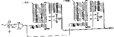
参考图11A,模拟量信号由线性阵列Pin-out传送到如图11C所示的电平转换器17。Referring to FIG. 11A , the analog signal is transmitted from the linear array Pin-out to the
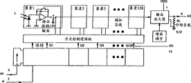
在图11C和图14中,电平转换器17将模拟量信号转变成数字形式。数字信号被传送到图12中的计数器U204.(PAL22V10)。该计数器给处于激活状态和那些不在激活状态的象素计数。然后象素的数字计数通过如图12A所示的二个锁存电路U205、U206(74ALS374)进行处理。数字计数被分别送到图12B所示的彼此连接工作的两个分别的缓冲器。这两个缓冲器(U301,U302)形成了该控制器和线性阵列YZ之间的接口。In FIG. 11C and FIG. 14, the
在图12C中,IntelTM196NU控制器用于从缓冲器中读取所接受的数据。控制器控制在硬币通过线性阵列过程中存储在静态RAM和EEPROM中的算法和指令。在这个过程中,从线性阵列中获得的数据与存储在快速存储器中的数据信息相比较。In Figure 12C, the Intel ™ 196NU controller is used to read the received data from the buffer. The controller controls the algorithms and instructions stored in static RAM and EEPROM as coins pass through the linear array. In this process, the data obtained from the linear array is compared with the data information stored in the flash memory.
接着从线性阵列中接受的数据流信息数字化,被数字化的信息一直存储在如图12D所示的两个静态存储器RAM中,直到微控制器能够取数据作分析。Then the data stream information received from the linear array is digitized, and the digitized information is stored in two static memory RAMs as shown in Fig. 12D until the microcontroller can fetch the data for analysis.
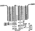
在图12E中,用快速存储器EEPROM存储控制器的指令。这些指令包括与装置标准有关的校准数据、已知硬币的数据,也包括在数学算法中使用的常数值。In Fig. 12E, the flash memory EEPROM is used to store the instructions of the controller. These instructions include calibration data related to device standards, data from known coins, and also constant values used in mathematical algorithms.
在图12F和图14(如数字18)中描述了LCD智能显示驱动器U401的电路。该显示驱动器为A25510。在图12F中,该驱动器也驱动用于打开或关闭两个阀门(如图12G所示)的继电器。两个通过该驱动器控制的光敏传感器用于检测通过通道52的硬币的进出。The circuit of the LCD intelligent display driver U401 is described in FIG. 12F and FIG. 14 (eg, numeral 18). The display driver is A25510. In Figure 12F, the driver also drives a relay that opens or closes two valves (as shown in Figure 12G). Two photosensitive sensors controlled by the driver are used to detect the entry and exit of coins through the
图12H和12I说明了在实施例电路中可用的印刷电路板的例子。Figures 12H and 12I illustrate examples of printed circuit boards that may be used in the embodiment circuits.
硬币识别Coin Recognition
当硬币4阻止一部分激光束照射在线性传感器阵列3时,线性阵列检测硬币在哪儿阻拦激光以及硬币在哪儿不阻拦激光,该信息用于获得硬币表面的特征指示。When the
在本发明的基本实施例中,确定或检测硬币表面至少一个长条的至少一部分的长度。例如这个长条可以是圆形硬币的直径,或非圆形硬币的最大截面,或可以是这些度量的一部分。通过将这些信息与已知硬币的相应数据相对照,获得的这些信息能够识别硬币。与早期的装置和方法相比,本发明使用激光获得这些信息,因此能更快识别更多的硬币。In a basic embodiment of the invention, the length of at least a portion of at least one strip on the surface of the coin is determined or detected. For example the bar could be the diameter of a round coin, or the largest cross-section of a non-round coin, or could be a fraction of these measures. By comparing this information with corresponding data for known coins, the information obtained enables the coin to be identified. The present invention uses laser light to obtain this information, thereby allowing more coins to be identified faster than earlier devices and methods.
在本发明的进一步实施例中,确定或检测硬币表面每个长条的至少一个部分的长度。In a further embodiment of the invention, the length of at least one portion of each strip on the face of the coin is determined or detected.
长条或这些长条在硬币边缘开始并延伸到硬币的约定点上。例如,在图13中,硬币被扫描的区域包括一些宽为s的长条。每个长条的一端70在硬币的边缘,每个长条的另一端71延伸到硬币的直径。然而,长条或这些长条可以从硬币的边缘延伸到非硬币边缘但不必必须是直径的任何约定位置。The strip or strips start at the edge of the coin and extend to an agreed point on the coin. For example, in FIG. 13, the area where the coin is scanned includes some strips of width s. One
最好激光束一个接一个地扫描长条或长条的一部分。在图13所示的实施例中,多条扫描线,63.5微米宽(即在线性阵列传感器3中单个象素的宽度),用于产生对应于硬币被扫描部分的一系列度量尺寸。因此这个过程可以比作是区域度量集成段的过程,这些区域度量集中在一起来提供硬币的特征指示。奇特形状的硬币,如英国50p的多边形硬币,通过测量表面积而很容易地得以识别。Preferably the laser beam scans the sliver or a part of the sliver one by one. In the embodiment shown in Figure 13, multiple scan lines, 63.5 microns wide (ie the width of a single pixel in the linear array sensor 3), are used to generate a series of metric dimensions corresponding to the scanned portion of the coin. The process can thus be likened to that of the integration segment of the regional metrics that are aggregated to provide an indication of the coin's characteristics. Oddly shaped coins, such as the polygonal British 50p coin, are easily identifiable by measuring their surface area.
这样的系统可以运行在10Hz到500KHz的频率之间。典型的时钟信号是500KHz。使用更现代元件的改进系统可以运行在5KHz到2000KHz之间,最好时钟信号为2MHz。如上面提到的实际实施例,当硬币滚过线性阵列3时,每秒可以产生大约39和15000个度量。然后以公知的方式将这些结果加在一起产生由系统扫描的整个面积的度量。可以想象OEM硬件上未来的发展在于元件,这些元件允许每秒产生更多的度量。元件速度上的这些改进仍然在本发明的范围内,并可以期待将来在电子学上的发展将使得本发明运行起来更有效。Such systems can operate at frequencies between 10Hz and 500KHz. A typical clock signal is 500KHz. Improved systems using more modern components can run between 5KHz and 2000KHz, preferably with a 2MHz clock signal. As in the practical example mentioned above, when the coin is rolled through the
本发明实施例中使用的累积序列中,每个扫描行有一个面积:In the accumulation sequence used in the embodiment of the present invention, each scan line has an area:
A=yδθA = yδθ
其中y=长条的高度where y = the height of the bar
而δθ=检测元件的宽度and δθ=the width of the detection element
给出:gives:
扫描行的总面积=yδθ+y1δθ+y2δθ+y3δθ+……The total area of the scan line = yδθ+y 1 δθ+y 2 δθ+y 3 δθ+…
以上函数公式表示在图13所显示的图解中。在图13中,每个长条的高度指的是Y值。一旦通过扫描硬币来获得Y值,就可以通过多种数学算法计算硬币的各种尺寸。通过应用中-纵坐标-规则(mid-ordinate-rule),如Trapezoidal规则或Simpson规则这样的算法获知。仅作为一个例子,给出该算法的详细内容。本发明并不局限于任何特别的数学算法。The above functional formula is represented in the diagram shown in FIG. 13 . In FIG. 13, the height of each bar refers to the Y value. Once the Y value is obtained by scanning the coin, various dimensions of the coin can be calculated through various mathematical algorithms. It is learned by applying a mid-ordinate-rule, an algorithm such as the Trapezoidal rule or the Simpson rule. Just as an example, the details of the algorithm are given. The present invention is not limited to any particular mathematical algorithm.
考虑硬币转动的半个周期,具有周期为π的周期性函数。想象硬币被分成具有等宽n个长条。每个长条是宽度s等于π/n。如图13所示,纵坐标用y0、y1、y2…yn-1,yn表示。
其中n=等宽的长条数where n = the number of strips of equal width
s=每个长条的宽度s = width of each strip
应当注意括号中的序列在yn-1截止。表达式yn被当作下一个循环的第一个纵坐标。It should be noted that the sequence in brackets ends at yn-1 . The expression y n is taken as the first ordinate of the next cycle.
根据以规则间隔出现的已知数组值可以获得yn、y1、y2□、的值。如果函数值没有在规则的间隔上给出,可以绘制一个y对x的图形,以x的规则间隔读取一套新的y值,等等,即
当以非常高的速度扫描硬币时,将用于补偿在检测中硬币速度或加速度之差的补偿电路的需要减到最小。When scanning coins at very high speeds, the need for compensation circuitry to compensate for differences in coin velocity or acceleration during detection is minimized.
因此,在本发明实施例中,硬币检测装置不仅仅能测量几何距离,如半径、直径和厚度。部分由于激光束的快速反映,高速率扫描也能使硬币检测装置反复测量多种几何尺寸。这些度量中的每一个重叠在一起提供硬币表面区域的一个区域度量。因此,通过将区域度量与其它已知硬币相对应区域度量相比较,来识别硬币。Therefore, in the embodiment of the present invention, the coin detection device can not only measure geometric distances, such as radius, diameter and thickness. Due in part to the fast reflection of the laser beam, the high scanning rate also enables the coin detection device to repeatedly measure multiple geometries. Each of these measures overlap to provide an area measure of the face area of the coin. Thus, a coin is identified by comparing the area measure to corresponding area measures of other known coins.
用一个求积的叠加序列获得硬币表面积是一个更精确识别硬币的方法,因为它避免了因为硬币边缘凹槽而使直径和半径不同所引起的问题。在测量硬币几何尺寸(如直径)的本发明实施例中,根据所测量的位置是否存在凹槽,由于凹槽所引起的集中变化可以影响直径的整个测量。比较起来,依据比较表面作为基础来识别硬币的那些实施例很少受由于凹槽存在引起的集中差异的影响。在硬币表面具有较大面积的测量中将由于凹槽所引起的变化考虑在内。Obtaining the coin surface area using a stacked sequence of quadratures is a more accurate method of identifying coins because it avoids the problems caused by differences in diameter and radius due to coin edge grooves. In embodiments of the invention where coin geometry (eg, diameter) is measured, depending on whether a groove is present at the location being measured, a lumped change due to the groove can affect the overall measurement of the diameter. In comparison, those embodiments that identify coins based on comparing surfaces are less affected by concentration differences due to the presence of grooves. Variations due to grooves are taken into account in measurements where the surface of the coin has a larger area.
激光束系统配合具有众多微小激光检测象素的激光检测器的使用,意味着可以测量特别细小的尺寸。因而,根据所做的测量接近凹槽还是远离凹槽,测量将有所不同。在测量中的不同意味着仅依靠一个直径或半径的测量将在硬币的识别中产生不确定性,因为它不能肯定是否所做的测量接近凹槽还是远离凹槽。当由许许多多的测量综合在一起以提供表面积测量时,通过比较表面区域的综合面积进行硬币间的比较。因此,在凹槽附近尺寸的集中变化不会引起综合区域所有表面中的明显变化。The use of the laser beam system in combination with a laser detector with numerous tiny laser detection pixels means that particularly small dimensions can be measured. Thus, the measurements will be different depending on whether the measurements are made close to or far from the groove. The difference in measurements means that relying on just one measurement of diameter or radius will create uncertainty in the identification of the coin as it cannot be sure whether the measurement was made close to or far from the groove. Coin-to-coin comparisons are made by comparing the combined areas of the surface areas when a large number of measurements are combined to provide a surface area measure. Therefore, a concentrated change in size near the groove does not cause a significant change in all surfaces of the integrated area.
借助于速度控制,所扫描图象的总和能够给出所检测硬币的真实尺寸。这种速度控制能够使用一个开口来获得,该开口在自由下落或旋转发生前阻挡硬币。With speed control, the summation of the scanned images gives the true size of the detected coin. This speed control can be obtained using an opening that blocks the coin before free fall or spin occurs.
进一步采用面积检测作为识别硬币的基础,对于检测不是圆形的硬币,如多边形硬币,特别有利。对于这样的非圆形硬币,依据硬币所检测的哪个部分,横向检测将产生大量不同的值。然而,对于这样硬币表面积的检测,将提供面积检测,可以一贯地将这样的面积检测作为将这些硬币与其他硬币进行比较的基础。Taking area detection further as a basis for coin recognition is particularly advantageous for detecting coins that are not round, such as polygonal coins. For such non-round coins, lateral detection will yield a number of different values depending on which part of the coin is detected. However, for detection of the surface area of such coins, an area detection will be provided, which can consistently be used as the basis for comparing these coins with other coins.
通过计算凹槽识别硬币Identify coins by counting grooves
硬币通常在边沿具有凹槽,在某些情况下,在一些流通硬币中发现内孔的边沿有凹槽。Coins often have grooves along the rim, and in some cases, the rim of the inner hole is found in some circulation coins.
在读取硬币的多个长条实施例中,传感器阵列单元3的分辨率是这样的,以便装置能够识别碾进硬币边沿的凹槽,如图13A。识别凹槽可以连同识别其他已描述的几何特征一同使用,或可以被用作为识别硬币的唯一装置。检测凹槽能使装置区别不同的硬币而不需任何进一步的,例如,重量或直径或正在进行感应方法的比较。例如,典型凸起部分的横截面通常在0.01mm2到0.04mm2范围内,在几乎是每个检测象素的3到11倍。因为通过这样的传感器阵列3能够清楚地分辨每一个凸起部分的面积。In the multiple strip embodiment for reading coins, the resolution of the
即使在一对硬币可能具有相同的直径、厚度和/或表面积这样少有的情况,这些其他方面相同的硬币也不可能具有相同的凹槽尺寸。因此,识别硬币凹槽的特征是识别大量硬币非常准确的方法,即使这些硬币具有非常相似的几何尺寸。Even in the rare instances where a pair of coins may have the same diameter, thickness and/or surface area, it is unlikely that these otherwise identical coins will have the same groove size. Therefore, identifying the features of coin grooves is a very accurate method of identifying a large number of coins, even if the coins have very similar geometric dimensions.
如图13A所示,也能够计算硬币边缘预定距离X内拥有的凹槽数。通过计算在预定距离内凹槽数量识别硬币的优点在于本装置和方法较少受磨损和/或损坏引起硬币中尺寸差别的影响。即使在由于磨损硬币的物理尺寸略微改变时,预定距离内凹槽的数量将保持不变。进一步,如果硬币的损坏集中在小部分,即使本装置读取没有损坏的硬币边缘时,硬币仍然可以被识别。As shown in FIG. 13A, it is also possible to count the number of grooves possessed within a predetermined distance X from the edge of the coin. An advantage of identifying coins by counting the number of grooves within a predetermined distance is that the apparatus and method are less susceptible to dimensional differences in coins caused by wear and/or damage. Even when the physical dimensions of the coin change slightly due to wear, the number of grooves within the predetermined distance will remain the same. Further, if the damage of the coin is concentrated in a small part, the coin can still be identified even when the device reads the edge of the coin without damage.
在进一步的实施例中,通过分析来自于扫描操作的全套输出,可以产生一个有关硬币轮廓的数字式定义图象。那么可以把这个测量到的图象同以前记忆的数字图象数相比较以便识别有关的硬币。这种处理方法用于补偿硬币任何受损边缘面积,这种补偿,例如,通过分析完好边缘的规则形状可以获得。该装置能够设置来拒绝在超过预先设置的百分比上不同于所存储图象的硬币。这些变化能由于,例如,硬币的磨损影响而产生。In a further embodiment, by analyzing the full set of outputs from the scanning operation, a digitally defined image of the outline of the coin can be produced. This measured image can then be compared with previously memorized digital image numbers to identify the associated coin. This treatment is used to compensate for any damaged edge area of the coin, which compensation can be obtained, for example, by analyzing the regular shape of the sound edge. The device can be set to reject coins that differ from the stored image by more than a preset percentage. These changes can be due to, for example, the wearing effect of coins.
在进一步的实施例中,激光辐射检测器可以包括由8部分128个象素组成的一个1024*1象素的线性传感器阵列。可以设想可以使用宽平面的线性传感器阵列,但本实施例的如此变化依赖于线性阵列设计上的技术的发展。In a further embodiment, the laser radiation detector may comprise a 1024*1 pixel linear sensor array consisting of 8 sections of 128 pixels. It is contemplated that a wide-planar linear sensor array could be used, but such a variation of this embodiment relies on the development of technology in the design of linear arrays.
本发明的实施例可以使用在大量硬币或辅币操作的设备中,如产品自动售货机、电话,锁,赌博机和自动钱币兑换设备。可以设想本实施例可以用于这样钱币接收装置,这里硬币的值可以属于信用卡或其它信用帐号(creditaccount)。Embodiments of the present invention may be used in mass coin or token operated devices such as product vending machines, telephones, locks, gaming machines and automatic money changers. It is contemplated that this embodiment may be used with money accepting devices where the value of the coin may belong to a credit card or other credit account.
为了辩识流通于全世界的大量金属硬币可以设计这样的硬币检测装置。由于本发明并不依赖于磁性感应方法,所以非金属硬币也可以被检测。这个装置也可以辩识非流通的辅币。Such a coin detection device can be designed to identify the large number of metal coins in circulation throughout the world. Since the present invention does not rely on magnetic sensing methods, non-metallic coins can also be detected. This device can also identify non-negotiable coins.
世界上广泛流通的硬币铸造得特别精致且重要地有可重复允许偏差。一些货币可以只在几个微米数量级上不同。因此,通过获得在几个微米级别上所测的硬币区域的几何尺寸量度,然后,把这个量度同已知硬币量度的数据记录相比较,可以辩识一个特别的硬币。这种精确度意味着能够辩识使用早期的装置和过程至今不容易辩识的一套套硬币。也意味着根据本发明的装置能够使用大量的硬币。不企图区分如微米数量级上的如此微小偏差的早期硬币检测装置将趋向于仅在有限的硬币与硬币之间的尺寸有实质性差别的一套硬币,例如,来自于单个国家的,是有用的。这些早期的装置很少可能有效地用于大套的硬币,而这里某些硬币在尺寸上可能仅有几个微米的不同。例如,在实验中,本发明的一套装置能够成功地识别一套超百种的不同硬币,并且本发明能够识别一套套更大的不同硬币。The coins that are widely circulated around the world are minted with particularly fine and important repeatable tolerances. Some currencies may differ by only a few microns. Thus, by obtaining a measure of the geometric dimensions of the area of the coin measured on the order of a few microns, and then comparing this measure with a data record of known coin measurements, a particular coin can be identified. This level of precision means being able to identify sets of coins that have hitherto been difficult to identify using earlier devices and processes. It also means that a large number of coins can be used with the device according to the invention. Early coin detection devices that did not attempt to distinguish such minute deviations as on the order of microns would tend to be useful only in a limited set of coins that differ substantially in size from coin to coin, e.g., from a single country . Few of these early devices were likely to be effective for large sets of coins, where some coins might differ in size by only a few microns. For example, in experiments, a set of devices of the present invention was able to successfully identify sets of over a hundred different coins, and the present invention was able to identify sets of larger sets of different coins.
仅通过举例提出了实施例,在所附权利要求的实质和范围内,修改是可以做出的。The embodiments are presented by way of example only, and modifications may be made within the spirit and scope of the appended claims.
Claims (63)
Applications Claiming Priority (2)
| Application Number | Priority Date | Filing Date | Title |
|---|---|---|---|
| GB9610603.4 | 1996-05-21 | ||
| GBGB9610603.4A GB9610603D0 (en) | 1996-05-21 | 1996-05-21 | Coin recognition apparatus |
Publications (2)
| Publication Number | Publication Date |
|---|---|
| CN1220750A CN1220750A (en) | 1999-06-23 |
| CN1135503C true CN1135503C (en) | 2004-01-21 |
Family
ID=10794052
Family Applications (1)
| Application Number | Title | Priority Date | Filing Date |
|---|---|---|---|
| CNB971944202A Expired - Fee Related CN1135503C (en) | 1996-05-21 | 1997-05-17 | Coin detection method and device, coin identification method, and coin or token operation device |
Country Status (16)
| Country | Link |
|---|---|
| EP (2) | EP0900431B1 (en) |
| JP (1) | JP2000510979A (en) |
| CN (1) | CN1135503C (en) |
| AR (1) | AR008601A1 (en) |
| AT (1) | ATE196378T1 (en) |
| AU (1) | AU716057B2 (en) |
| BR (1) | BR9709010B1 (en) |
| CA (1) | CA2255642C (en) |
| DE (1) | DE69703103T2 (en) |
| ES (1) | ES2150766T3 (en) |
| GB (2) | GB9610603D0 (en) |
| NZ (1) | NZ331979A (en) |
| SA (1) | SA97180133B1 (en) |
| TW (1) | TW352426B (en) |
| WO (1) | WO1997044760A1 (en) |
| ZA (1) | ZA974389B (en) |
Families Citing this family (12)
| Publication number | Priority date | Publication date | Assignee | Title |
|---|---|---|---|---|
| DE19922489A1 (en) | 1999-05-15 | 2000-11-23 | Nat Rejectors Gmbh | Method for recognizing the spatial configuration of coins |
| DE19951458B4 (en) * | 1999-10-26 | 2009-02-05 | Scan Coin Industries Ab | Device for counting and / or sorting coins |
| DE10028934A1 (en) * | 1999-10-26 | 2002-01-10 | Zimmermann Gmbh & Co Kg F | Device for counting and / or sorting coins |
| DE10018198B4 (en) * | 2000-04-12 | 2015-07-23 | Phoenix Mecano Digital Elektronik Gmbh | Sensor device and method for contactless scanning of a surface of an object |
| GB2369710B (en) * | 2000-12-04 | 2004-04-21 | Ezio Panzeri | Coin identification |
| JP2002259977A (en) * | 2001-02-26 | 2002-09-13 | Nidec Copal Corp | Reader |
| JP4711738B2 (en) * | 2005-05-17 | 2011-06-29 | 旭精工株式会社 | Disc hopper with fraud prevention device |
| ES2346612B1 (en) | 2008-03-10 | 2011-08-04 | Azkoyen Medios De Pago, S.A. | SYSTEM AND METHOD OF SELECTION OF COINS. |
| KR101812859B1 (en) | 2010-07-20 | 2017-12-27 | 에프. 호프만-라 로슈 아게 | Device for detecting an analyte in a bodily fluid |
| EP2787488A1 (en) | 2013-04-02 | 2014-10-08 | Ezio Panzeri | Coin checking |
| CN105160754B (en) * | 2015-06-25 | 2019-12-10 | 中钞长城金融设备控股有限公司 | Coin surface quality detection device based on height measurement and detection method thereof |
| CN109509291A (en) * | 2017-09-15 | 2019-03-22 | 南京造币有限公司 | A kind of coin edge figure line check device |
Family Cites Families (10)
| Publication number | Priority date | Publication date | Assignee | Title |
|---|---|---|---|---|
| AT355357B (en) * | 1976-07-29 | 1980-02-25 | Landis & Gyr Ag | OPTICAL COIN TESTER |
| GB1582847A (en) * | 1976-12-02 | 1981-01-14 | Mars Inc | Coin testing device |
| GB2010559A (en) * | 1977-08-03 | 1979-06-27 | Vgl Ind Ltd | Apparatus for determining the denomination of coins in coin freed mechanism |
| US4474281A (en) * | 1982-06-07 | 1984-10-02 | General Signal Corporation | Apparatus and method for coin diameter computation |
| FI81458C (en) * | 1987-03-31 | 1990-10-10 | Inter Marketing Oy | Device for identification of coins or the like |
| WO1988007721A1 (en) * | 1987-04-02 | 1988-10-06 | Unisys Corporation | Associative address translator for computer memory systems |
| GB2212313B (en) * | 1987-11-13 | 1991-10-30 | Coin & Micro Systems Limited | Article identification |
| DD296769A5 (en) * | 1990-07-18 | 1991-12-12 | Act Gesellschaft Fuer Soft- Und Hardwaresysteme Mbh,De | ARRANGEMENT FOR EXAMINING THE PHYSICAL PROPERTIES OF MUENCES |
| US5360095A (en) * | 1992-04-07 | 1994-11-01 | Pom Incorporated | Power conserving electronic parking meter |
| DE4320123A1 (en) * | 1993-06-18 | 1995-01-12 | Graebener Pressensysteme Gmbh | Coin validator |
-
1996
- 1996-05-21 GB GBGB9610603.4A patent/GB9610603D0/en active Pending
-
1997
- 1997-05-17 BR BRPI9709010-7A patent/BR9709010B1/en not_active IP Right Cessation
- 1997-05-17 EP EP97918315A patent/EP0900431B1/en not_active Expired - Lifetime
- 1997-05-17 DE DE69703103T patent/DE69703103T2/en not_active Expired - Lifetime
- 1997-05-17 EP EP99204271A patent/EP0996098A3/en not_active Withdrawn
- 1997-05-17 NZ NZ331979A patent/NZ331979A/en unknown
- 1997-05-17 GB GB9819877A patent/GB2327136A/en not_active Withdrawn
- 1997-05-17 AT AT97918315T patent/ATE196378T1/en active
- 1997-05-17 CN CNB971944202A patent/CN1135503C/en not_active Expired - Fee Related
- 1997-05-17 ES ES97918315T patent/ES2150766T3/en not_active Expired - Lifetime
- 1997-05-17 WO PCT/IB1997/000569 patent/WO1997044760A1/en not_active Ceased
- 1997-05-17 AU AU26484/97A patent/AU716057B2/en not_active Ceased
- 1997-05-17 JP JP09541928A patent/JP2000510979A/en active Pending
- 1997-05-17 CA CA002255642A patent/CA2255642C/en not_active Expired - Fee Related
- 1997-05-20 ZA ZA974389A patent/ZA974389B/en unknown
- 1997-05-21 AR ARP970102168A patent/AR008601A1/en active IP Right Grant
- 1997-05-21 TW TW086106936A patent/TW352426B/en active
- 1997-06-14 SA SA97180133A patent/SA97180133B1/en unknown
Also Published As
| Publication number | Publication date |
|---|---|
| CN1220750A (en) | 1999-06-23 |
| CA2255642C (en) | 2008-04-01 |
| EP0900431A1 (en) | 1999-03-10 |
| ATE196378T1 (en) | 2000-09-15 |
| SA97180133B1 (en) | 2006-09-05 |
| CA2255642A1 (en) | 1997-11-27 |
| WO1997044760A1 (en) | 1997-11-27 |
| AR008601A1 (en) | 2000-02-09 |
| GB9819877D0 (en) | 1998-11-04 |
| BR9709010B1 (en) | 2008-11-18 |
| JP2000510979A (en) | 2000-08-22 |
| BR9709010A (en) | 2000-01-04 |
| DE69703103D1 (en) | 2000-10-19 |
| TW352426B (en) | 1999-02-11 |
| AU716057B2 (en) | 2000-02-17 |
| ES2150766T3 (en) | 2000-12-01 |
| GB2327136A (en) | 1999-01-13 |
| DE69703103T2 (en) | 2001-01-18 |
| EP0900431B1 (en) | 2000-09-13 |
| EP0996098A2 (en) | 2000-04-26 |
| EP0996098A3 (en) | 2002-07-31 |
| ZA974389B (en) | 1999-03-15 |
| AU2648497A (en) | 1997-12-09 |
| GB9610603D0 (en) | 1996-07-31 |
| NZ331979A (en) | 2000-08-25 |
| HK1018919A1 (en) | 2000-02-11 |
Similar Documents
| Publication | Publication Date | Title |
|---|---|---|
| CN1135503C (en) | Coin detection method and device, coin identification method, and coin or token operation device | |
| US6142285A (en) | Coin testing apparatus and method | |
| CN1190757C (en) | Paper testing device | |
| CN1038529C (en) | Optical methods and apparatus | |
| US12240770B2 (en) | Systems and method for correction of positionally dependent electromagnetic radiation detected from objects within a fluid column | |
| US20100039818A1 (en) | Numismatic storage container to prevent counterfeiting of coinage | |
| CN101057263A (en) | Sheet recognizing device and method | |
| CN100394433C (en) | Fingerprint Imaging Optical Device | |
| US10685523B1 (en) | Systems, methods and devices for processing batches of coins utilizing coin imaging sensor assemblies | |
| Hulber | Overview of PADC nuclear track readers. Recent trends and solutions | |
| CN1956014A (en) | Medal selecting device in medal input device of game machine | |
| HK1018919B (en) | Coin testing apparatus and method | |
| RU2172019C2 (en) | Method and device for coin checking and method for coin identification | |
| JPS59200385A (en) | Electronic currency selector | |
| JPS59200386A (en) | Currency shape detector | |
| SE9001484L (en) | CURRENCY AT COIN SORTING AND / OR COUNTING MACHINE |
Legal Events
| Date | Code | Title | Description |
|---|---|---|---|
| C06 | Publication | ||
| PB01 | Publication | ||
| C10 | Entry into substantive examination | ||
| SE01 | Entry into force of request for substantive examination | ||
| C14 | Grant of patent or utility model | ||
| GR01 | Patent grant | ||
| ASS | Succession or assignment of patent right |
Owner name: DIGITAL CO.,LTD. Free format text: FORMER OWNER: EZIO PANZERI; BURHAN AL-HASHEMI Effective date: 20070413 |
|
| C41 | Transfer of patent application or patent right or utility model | ||
| TR01 | Transfer of patent right |
Effective date of registration: 20070413 Address after: Delaware Patentee after: Digital company Address before: Milan Italy Co-patentee before: Burham Alfred - Hasen M. Patentee before: Ezio Panzeri |
|
| CF01 | Termination of patent right due to non-payment of annual fee | ||
| CF01 | Termination of patent right due to non-payment of annual fee |
Granted publication date: 20040121 Termination date: 20160517 |