Tunnel comprehensive excavation trolley
Technical Field
The invention relates to the technical field of tunnel construction, in particular to a comprehensive tunnel excavation trolley.
Background
The tunnel construction site has poor environment and lower safety, and along with the great increase of domestic labor cost and increasingly strict requirements on tunnel construction safety, the tunnel construction is intelligent, informationized and mechanized. The tunnel construction in China has been partially mechanized, and for example, spray anchoring, slag tapping, waterproof board laying, secondary lining and the like are all constructed by corresponding mature machines. The existing tunnel face matched mechanical construction operation machinery of each procedure comprises: the mechanical equipment comprises a rock drilling trolley, an arch center mounting trolley, a wet spraying machine, an anchor rod trolley and the like. However, these mechanical devices can only complete one procedure in tunnel construction, after one procedure is completed, the corresponding mechanical device needs to exit from the tunnel excavation surface, and the mechanical device of the next procedure needs to enter the construction surface at the front end of the tunnel, so that the mechanical devices in different procedures are frequently replaced, the construction efficiency is low, and meanwhile, the cost and the maintenance cost of the mechanical devices are high. Through the analytical research of the existing construction method and construction equipment, a novel multifunctional comprehensive operation trolley is developed, and is the development direction of the tunnel construction technology in future.
Disclosure of Invention
The invention provides a tunnel comprehensive excavation trolley which integrates tunnel excavation and supporting, can realize the work of drilling and blasting holes, charging, arch center installation, milling and excavation, anchor rods, concrete wet blasting and the like, and has the advantages of few constructors, higher construction efficiency, high construction safety, economy and practicability.
The technical scheme adopted for realizing the above purpose of the invention is as follows:
a tunnel comprehensive excavation trolley at least comprises a trolley body, an electric hydraulic system, a working arm, a traveling mechanism and a supporting mechanism, wherein the electric hydraulic system is positioned on the trolley body and used for providing operation power for each component on the trolley, the working arm is used for tunnel excavation and supporting construction, the traveling mechanism and the supporting mechanism are connected to the bottom of the trolley body, the trolley body comprises two racks and two working platforms, the two racks are vertically arranged and respectively comprise an upper rack and a lower rack, the upper rack comprises an upper top plate and an upper support which is fixedly connected to the lower portion of the upper top plate, the lower rack comprises a lower top plate and a lower support which is fixedly connected to the lower portion of the lower top plate, the upper rack is connected to the lower top plate through a fourth longitudinal moving mechanism, so that the upper rack is connected to the lower rack and the upper rack longitudinally moves along the lower rack, and the working platforms are connected to two sides of the upper rack and the lower rack in a hanging mode; the working arm is arranged on the rack and is connected with the rack through a first longitudinal moving mechanism, the working arm is driven by the first longitudinal moving mechanism to move longitudinally along the rack, and the head of the working arm is connected with different working accessories for the procedures of drilling, wet blasting, milling and digging and arch erection in tunnel construction through a quick-change connector;
the vehicle body is also provided with an arch installing unit which comprises an arch installing vehicle, an arch transport vehicle, a cantilever crane, a second longitudinal moving mechanism, a third longitudinal moving mechanism, a mechanical arm and an arch support rod, wherein the arch installing vehicle, the arch transport vehicle, the cantilever crane, the second longitudinal moving mechanism, the third longitudinal moving mechanism, the mechanical arm and the arch support rod are used for pre-assembling a plurality of roofs, the second longitudinal moving mechanism and the third longitudinal moving mechanism are both arranged on the upper rack and are arranged in parallel with the first longitudinal moving mechanism, the third longitudinal moving mechanism is arranged on the outer side of the upper rack, the second longitudinal moving mechanism is arranged on the inner side of the upper rack, the arch installing vehicle comprises a frame, an arch jacking assembly and an installing vehicle longitudinal moving assembly which are integrally arched, the frame comprises a rectangular top frame, support frames which are connected with the top frame and are in a semi-arch shape, and a longitudinal frame which is arranged along the direction of the trolley and is connected between the two parallel support frames, the top frame, the semi-arch support frames and the longitudinal frame jacking assembly are distributed on the top frame in a matrix manner, the arch frame jacking assembly distributed along the direction perpendicular to the trolley is a group, the arch frame jacking assembly is provided with more than three groups and is used for supporting a plurality of arch frames, the installation vehicle longitudinal movement assembly is connected to the bottom of the supporting frame and straddles the second longitudinal movement mechanism, the left end and the right end of the arch frame installation vehicle are installed on the second longitudinal movement mechanism and longitudinally move through the second longitudinal movement mechanism, the arch frame transport vehicle is installed on the third longitudinal movement mechanism and longitudinally move through the third longitudinal movement mechanism, the mechanical arm and the arch frame supporting rod are installed and fixed at the front end of the working platform, the arch frame supporting rod is located above the mechanical arm, and the cantilever crane is arranged at the rear end of the upper rack.
The number of the working arms is six, two working arms are respectively arranged on the upper surface of the upper top plate and the lower surfaces of the upper support and the lower top plate, the working arms on the upper top plate and the upper support are rightly arranged on the first longitudinal moving mechanism, and the working arms on the lower top plate are inversely suspended and arranged on the first longitudinal moving mechanism; the working arm comprises a rack, a rotary component, an amplitude variation component, a basic arm frame and a telescopic arm frame, wherein the rack is connected with the first longitudinal movement mechanism, the basic arm frame is connected with the rack through the rotary component and moves back and forth in the transverse direction under the drive of the rotary component, the telescopic arm frame is connected with the basic arm frame through the amplitude variation component and moves back and forth in the vertical direction under the drive of the amplitude variation component, and a telescopic oil cylinder is installed in the telescopic arm frame and moves back and forth in the longitudinal direction under the drive of the telescopic oil cylinder, so that the working arm works in three freedom degree directions.
The arch frame jacking assembly comprises a jacking oil cylinder and a groove-shaped jacking piece connected to the top of the jacking oil cylinder, the height of the jacking piece is adjusted through the jacking oil cylinder, the installation vehicle longitudinal movement assembly comprises a longitudinal movement frame which is arranged along the direction of the trolley and connected to the bottoms of the two parallel supporting frames, an installation vehicle travelling wheel arranged at the bottom of the longitudinal movement frame, a sixth hydraulic motor and a motor output shaft gear which are fixedly connected to the side surface of the longitudinal movement frame, and a sixth gear fixedly connected to the installation vehicle travelling wheel, the installation vehicle travelling wheel straddles the second longitudinal movement mechanism, the motor output shaft gear is meshed with the sixth gear, and the sixth hydraulic motor drives the motor output shaft gear and the sixth gear to transmit and drive the integral longitudinal movement of the arch frame installation vehicle; two sides of the top frame, which are positioned at the front end and the rear end of the trolley, are connected with a transverse H-shaped telescopic joint through telescopic oil cylinders, more than one group of arch jacking assemblies are arranged on the telescopic joint, and the distance between the arch jacking assemblies on the telescopic joint and the arch jacking assemblies on the top frame is adjusted through the telescopic oil cylinders, so that the distance between every two arches is adjusted; the support frame is of a telescopic structure, and the height of the support frame is adjusted through a lifting oil cylinder connected between the longitudinal frame and the longitudinal moving frame.
The upper support and the lower support are both of telescopic structures and are uniformly distributed and connected with lifting oil cylinders, so that the heights of the upper rack and the lower rack are adjusted along with the lifting oil cylinders; the fourth longitudinal moving mechanism comprises a rack rail fixedly connected to the lower top plate, a rack support fixedly connected to the bottom of the upper support and arranged in the rack rail, a fourth riding wheel, a fourth riding rail, a fourth pulley arranged on two sides of the rack support and close to the rear end of the trolley, a fourth rack connected to the bottom of the rack support, and a fourth hydraulic motor and a fourth gear fixedly connected to the upper support, wherein the rack rail is of a groove structure assembled by two steel rails with cross sections in a [ -shape, the fourth gear is meshed with the fourth rack, the rack is driven by the fourth hydraulic motor to drive the gear rack to enable the rack support and the upper rack to integrally move on the rack rail, the fourth riding rail is connected to the bottom of the rack support and arranged in parallel with the fourth rack, and the fourth riding wheel straddles the fourth riding rail and is fixedly connected to the upper support close to the front end of the trolley, the rack support is prevented from being separated from the rack rail when longitudinally moving, and the length of the rack rail is consistent with that of the rack.
The first longitudinal moving mechanism comprises an I-shaped working arm track, a working arm support saddle, a first rack, a first hydraulic motor and a first gear, wherein the working arm support saddle is arranged on the working arm track in a straddling mode, the first rack is fixed on the side face of the working arm track, and the first hydraulic motor and the first gear are fixedly connected and are positioned on the working arm support saddle; the working arm rails are connected to the upper top plate, the lower top plate and the upper support in a distributed mode, the working arm rails on the upper support are fixedly connected to the upper support through the side frame, extending along the inner side of the upper support, at the bottom of the upper support, the working arm rails are arranged along the direction of the trolley, the length of the working arm rails is identical to that of the trolley, and the working arm supports are connected with the working arms, so that the working arms can move longitudinally along the trolley.
The second longitudinal moving mechanism is of a double longitudinal moving structure and comprises a fixed rail, a sliding rail, a second supporting wheel, a second supporting rail, second pulleys, a second rack, a second hydraulic motor and a second gear, wherein the fixed rail is fixedly connected to the upper surface of the upper rack, the sliding rail is arranged in the fixed rail, the second pulleys are arranged on two sides of the sliding rail and are close to the rear end of the trolley, the second rack is connected to the bottom of the sliding rail, the second hydraulic motor and the second gear are fixedly connected to the upper support, the fixed rail is of a groove type structure formed by assembling two steel rails with cross sections in a [ -shape, the second gear is meshed with the second rack and drives the gear rack to transmit through the second hydraulic motor so that the sliding rail moves on the fixed rail, the second supporting rail is connected to the bottom of the sliding rail and is arranged in parallel with the second rack, and the second supporting wheel straddles the second supporting rail and is fixedly connected to the upper support close to the front end of the trolley, so that the sliding rail is prevented from being separated from the fixed rail during longitudinal moving; the top of the sliding rail is provided with an arch installing vehicle rail, the arch installing vehicle is installed on the arch installing vehicle rail and moves longitudinally along the sliding rail, and the lengths of the sliding rail and the arch installing vehicle rail are consistent with the length of the upper rack.
The working platform is characterized in that a suspension bracket is connected to one side of the working platform and connected with the rack through the suspension bracket, the suspension bracket is connected to two sides of the rack in a suspension manner through a fifth longitudinal moving mechanism to enable the working platform to move longitudinally along the rack, the fifth longitudinal moving mechanism comprises a platform rail connected to the side face of the rack, a fifth rack arranged in the platform rail, suspension discs which are distributed on the suspension bracket and clamped in the platform rail, and a fifth hydraulic motor and a fifth gear which are fixedly connected to the suspension bracket, the platform rail is of a groove type structure, the platform rails are arranged in parallel, the suspension discs are distributed in two rows in parallel at corresponding positions, the fifth gear is meshed with the fifth rack, and the fifth hydraulic motor drives the gear rack to transmit, so that the suspension bracket moves on the platform rail, and the working platform moves along the rack; the telescopic platform is connected and arranged on the working platform through the transverse moving oil cylinder, the telescopic platform is driven by the transverse moving oil cylinder to move transversely along one side of the working platform, away from the rack, the telescopic platform is located at the front end of the working platform, and a rack ladder is arranged at the rear end of the working platform, so that a constructor can get on or off the trolley conveniently.
The working accessories are a rock drill assembly, a wet spraying machine assembly, a planing and milling machine assembly and a grabbing hand assembly; when the trolley is used for carrying out concrete wet spraying operation, the working accessory is a wet spraying machine assembly, and the trolley is provided with a wet spraying material supply system, wherein the wet spraying material supply system comprises a pumping device, an accelerator quantitative filling device, a wheel type walking device, an automatic intelligent device and a wireless remote controller.
The third longitudinal moving mechanism comprises an I-shaped carrier vehicle track, a carrier vehicle support saddle on the carrier vehicle track, carrier vehicle traveling wheels arranged at the bottom of the carrier vehicle support saddle, a third hydraulic motor, a motor output shaft gear and a third gear, wherein the third hydraulic motor and the motor output shaft gear are fixedly connected to the working arm support saddle, the third gear is fixedly connected to the carrier vehicle traveling wheels, the carrier vehicle support saddle is fixedly connected with the arch carrier vehicle, the motor output shaft gear is meshed with the third gear, the third hydraulic motor drives the motor output shaft gear and the third gear to transmit and drive the arch carrier vehicle to integrally and longitudinally move, the carrier vehicle track is connected to the upper rack, and the length of the carrier vehicle track is consistent with that of the upper rack; the arch transport vehicle comprises a stand column of a telescopic structure and an arch clamping device connected to the top of the stand column, wherein the height of the stand column is adjusted through a lifting oil cylinder.
The arch support rod is connected with an inclined support rod through a pin shaft, so that the arch support rod can be conveniently laid and erected.
Compared with the prior art, the comprehensive tunnel excavation trolley provided by the invention has the following advantages: 1. the comprehensive tunnel excavation trolley integrates tunnel excavation and support, can realize the work of drilling and blasting holes, charging, arch center installation, milling and excavation, anchor rods, concrete wet spraying and the like, saves the time for frequently replacing construction machinery in different procedures in mechanized construction, improves the construction efficiency, and simultaneously reduces the cost of machinery matched with tunnel construction and the maintenance cost. 2. The comprehensive tunnel excavation trolley provided by the invention can meet the tunnel construction requirements of various construction methods such as a full-section method, a two-step method and a three-step method, and has strong adaptability. 3. The comprehensive tunnel excavation trolley provided by the invention does not exit from the tunnel excavation surface during deslagging, and can perform grouping pre-assembly of the arch frame, the connecting ribs and the reinforcing mesh sheet while deslagging, so that the construction efficiency is improved. 4. The comprehensive tunnel excavation trolley is provided with six working arms, more working arms can be arranged according to needs, each working arm operates independently, the construction efficiency is high, in addition, after a single working arm breaks down, the working arms can be retracted to the rear end of the trolley through the longitudinal moving mechanism, the operation of other working arms is not influenced, meanwhile, other working arms can also cover the working area of the broken-down working arm, and the whole construction is not influenced. 5. The drilling machine is provided with six working arms, the degree of freedom of the working arms is high, the external inserting angle of a drilling hole is small, and the overbreak and the underexcavation are easy to control. 6. The number of layers of the working platforms is consistent with that of the working arms, the working platforms are located below the working arms, and the working platforms move longitudinally and extend transversely through the third longitudinal moving mechanism and the transverse moving oil cylinder, so that the charging operation of different tunnel construction methods can be met, and the charging speed is high. 7. The arch center mounting trolley provided by the invention can realize quick mounting of three arch centers and has higher mounting efficiency.
Drawings
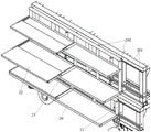
Fig. 1 is a three-dimensional structure view of a tunnel comprehensive excavation trolley provided by the invention;
fig. 2 is a partial structural view of the tunnel comprehensive excavation trolley provided by the invention;
FIG. 3 is a block diagram of the stand of the present invention;
FIG. 4 is a structural view of a fourth longitudinal movement mechanism in the present invention;
wherein (a) is a side view of the fourth longitudinal moving mechanism, and (b) (c) and (d) are both cross-sectional views of the fourth longitudinal moving mechanism;
FIG. 5 is a structural view of a first longitudinal movement mechanism according to the present invention;
fig. 6 is a front view of the comprehensive tunnel excavation trolley provided by the present invention, wherein (b) is a partial enlarged view of a in (a);
FIG. 7 is a block diagram of the working arm of the present invention;
FIG. 8 is a view showing the construction of the working attachment of the present invention;
wherein, (a) is a rock drill assembly, (b) is a wet spraying machine assembly, and (c) is a planing and milling machine assembly;
FIG. 9 is a block diagram of the quick-change coupler of the present invention;
wherein (a) is a structure diagram of each part of the quick-change connector, and (b) is a structure diagram of the assembled quick-change connector;
FIG. 10 is a view showing the construction of the working platforms on both sides of the upper stage in the present invention;
FIG. 11 is a drawing of the connection of the work platform to the gantry of the present invention;
FIG. 12 is a block diagram of the jib crane, manipulator and arch support bar of the present invention;
wherein (a) is a cantilever crane, (b) is a manipulator, and (c) is an arch support rod;
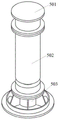
FIG. 13 is a block diagram of an arch transport vehicle and a third longitudinal movement mechanism of the present invention;
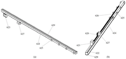
FIG. 14 is a structural view of a second longitudinal movement mechanism in the present invention;
wherein (a) is a side view of the second longitudinal moving mechanism, and (b) (c) (d) are cross-sectional views of the second longitudinal moving mechanism;
FIG. 15 is a perspective view of a second longitudinal movement mechanism of the present invention in a different direction;
FIG. 16 is a perspective view of the arch mounting vehicle of the present invention in a different orientation;
FIG. 17 is a structural view of a running gear of the present invention, wherein (a) and (b) are perspective views in different directions;
FIG. 18 is a structural view of a support mechanism of the present invention;
FIG. 19 is a schematic diagram of a wet blasting material supply system used in conjunction with a tunnel excavation trolley according to the present invention;
FIG. 20 is a first schematic view of a full-section construction method of the integrated trolley for tunnel excavation and support provided by the invention;
FIG. 21 is a second schematic view of a full-section construction method of the tunnel excavation and support integrated trolley provided by the invention;
FIG. 22 is a third schematic view of a construction of the tunnel excavation supporting integrated trolley by a full cross-section method;
fig. 23 is a fourth schematic view of the construction of the tunnel excavation and support integrated trolley by the full cross-section method provided by the invention;
fig. 24 is a fifth construction schematic diagram of the tunnel excavation and support integrated trolley according to the full-section method provided by the invention;
fig. 25 is a sixth schematic view of construction of the tunnel excavation and support integrated trolley by the full cross-section method provided by the invention;
fig. 26 is a seventh construction schematic diagram of the tunnel excavation and support integrated trolley according to the full-section method provided by the invention;
fig. 27 is an eighth schematic construction diagram of the full-section method of the tunnel excavation and support integrated trolley provided by the invention;
FIG. 28 is a first schematic construction diagram of a three-step method of the integrated trolley for tunnel excavation and support provided by the invention;
FIG. 29 is a second schematic diagram of construction of the integrated trolley for tunnel excavation and support by a three-step method, provided by the invention;
FIG. 30 is a third schematic construction diagram of the three-step method of the tunnel excavation and support integrated trolley provided by the invention;
fig. 31 is a fourth schematic view of construction of the tunnel excavation and support integrated trolley by the three-step method provided by the invention;
fig. 32 is a schematic diagram of a three-step method construction of the tunnel excavation and support integrated trolley provided by the invention;
fig. 33 is a schematic diagram six of construction of the integrated trolley for tunnel excavation and support provided by the invention by a three-step method;
in the figure: 1-a rack, 101-an upper rack, 1011-an upper top plate, 1012-an upper support, 1013-a side frame, 102-a lower rack, 1021-a lower top plate, 1022-a lower support, 103-a fourth longitudinal movement mechanism, 1031-a rack rail, 1032-a rack support, 1033-a fourth riding wheel, 1034-a fourth riding rail, 1035-a fourth pulley, 1036-a fourth rack, 1037-a fourth hydraulic motor, 1038-a fourth gear and 104-a lifting cylinder A;
20-a working platform, 21-a suspension bracket, 22-a telescopic platform, 23-a transverse moving oil cylinder, 24-a ladder, 200-a fifth longitudinal moving mechanism, 201-a platform track and 202-a suspension disc;
3-a working arm, 301-a frame, 302-a rotary component, 303-an amplitude-changing component, 304-a basic arm support and 305-a telescopic arm support;
4-running gear, 401-steering assembly, 402-suspension assembly, 403-tires, 404-drive motor, 405-axle;
5-a supporting mechanism, 501-a connecting seat, 502-a supporting oil cylinder and 503-a supporting seat;
61-arch mounting vehicle, 611-vehicle frame, 6111-top frame, 6112-support frame, 6113-longitudinal frame, 612-arch jacking assembly, 6121-jacking oil cylinder, 6122-jacking piece, 613-mounting vehicle longitudinal moving assembly, 6131-longitudinal moving frame, 6132-mounting vehicle traveling wheel, 6133-sixth hydraulic motor, 614-telescopic joint and 615-lifting oil cylinder B;
62-a second longitudinal moving mechanism, 621-a fixed rail, 622-a sliding rail, 623-a second riding wheel, 624-a second riding rail, 625-a second pulley, 626-a second rack, 627-a second hydraulic motor, 628-a second gear and 629-an arch mounting vehicle rail;
63-an arch carrier vehicle, 631-an upright post, 632-an arch clamping device, 64-a third longitudinal moving mechanism, 641-a carrier vehicle track, 642-a carrier vehicle support, 65-a cantilever crane, 66-a manipulator, 67-an arch support rod and 68-an inclined support rod;
7-a first longitudinal moving mechanism, 701-a working arm track, 702-a working arm support, 703-a first rack, 704-a first hydraulic motor, 705-a first gear;
8-quick-change connector, 801-working arm connector, 8011-hook, 802-working accessory connector, 8021-hanging groove, 803-hydraulic pin shaft, 9-rock drill assembly, 10-wet blasting machine assembly, 11-planing and milling machine assembly and 12-wet blasting material supply system.
Detailed Description
The present invention will be described in detail with reference to the accompanying drawings.
The integral structure of the comprehensive tunnel excavation trolley provided by the invention is shown in fig. 1 and fig. 2, and comprises a trolley body, an electric hydraulic system, a working arm 3, a traveling mechanism 4, a supporting mechanism 5 and an arch installing unit, wherein the electric hydraulic system is positioned on the trolley body and is used for providing operation power for all components on the trolley, the working arm is used for tunnel excavation and supporting construction, the traveling mechanism 4 and the supporting mechanism 5 are connected to the bottom of the trolley body, and the trolley body comprises a rack 1 and a working platform 20. The comprehensive tunnel excavation trolley can realize the integration of drilling and blasting holes, charging, arch center pre-installation, anchor rod holes, anchor rod installation and grouting, arch center net piece installation, milling and excavation operation, concrete wet spraying operation and other works, and is suitable for tunnel construction of various construction methods such as a full-section method, a two-step method, a three-step method and the like.
In this embodiment, two vertically arranged gantries 1 are respectively an upper gantry 101 and a lower gantry 102, the upper gantry comprises an upper top plate 1011, an upper bracket 1012 connected and fixed under the upper top plate and a side frame 1013 connected to the bottom of the upper bracket and extending along the inner side of the upper bracket, the lower gantry comprises a lower top plate 1021 and a lower bracket 1022 connected and fixed under the lower top plate, the upper bracket is connected to the lower top plate through a fourth longitudinal movement mechanism 103, so that the upper gantry is connected to the lower gantry and the upper gantry moves longitudinally along the lower gantry; the upper support and the lower support are of telescopic structures and are connected with lifting oil cylinders A104 in a uniformly distributed mode, so that the heights of the upper rack and the lower rack are adjusted along with the lifting oil cylinders. The structure of the rack is shown in fig. 3, and two lifting oil cylinders are respectively arranged on the left side and the right side of the upper rack and the lower rack. When the tunnel integrated excavation trolley is constructed, the upper rack can move forwards longitudinally by 0-4 m through the longitudinal movement mechanism, in addition, the height of each rack can be adjusted by 0-1 m, the whole height of the tunnel integrated excavation trolley can be adjusted by 0-2 m, and the full-section construction can be met while the step method construction can be adapted. In addition, the height of the lower rack can reach 3.5-4.5 m (including the height of a walking mechanism) through the lifting oil cylinder, when drilling and blasting are completed, the slag discharging vehicle can enter the excavation surface from the lower part of the lower rack and discharge slag, the tunnel comprehensive excavation trolley can not exit the tunnel excavation surface, and the arch frame, the connecting ribs and the reinforcing mesh can be pre-assembled in groups while discharging slag, so that the construction efficiency is improved.
The fourth longitudinal moving mechanism 103 comprises a rack rail 1031 fixed on the lower top plate, a rack support 1032 fixed on the bottom of the upper support and arranged in the rack rail, a fourth riding wheel 1033, a fourth riding rail 1034, a fourth pulley 1035 arranged on two sides of the rack support and close to the rear end of the trolley, a fourth rack 1036 connected to the bottom of the rack support, and a fourth hydraulic motor 1037 and a fourth gear 1038 connected on the upper support and fixedly connected, wherein the rack rail is a groove structure assembled by two steel rails with cross sections in a shape of [, the fourth gear is meshed with the fourth rack, the rack transmission is driven by the fourth hydraulic motor to enable the rack support and the upper support to integrally move on the rack rail, the structure of the fourth longitudinal moving mechanism is as shown in figure 4, the fourth riding rail is connected to the bottom of the rack support and arranged in parallel with the fourth rack, the fourth riding wheel straddles the fourth riding rail and is connected and fixed on the upper support close to the front end of the trolley, the support of the rack is prevented from being separated from the track of the rack during longitudinal movement; the length of the rack rail is consistent with that of the rack.
The working arm 3 is arranged on the rack and is connected with the rack through a first longitudinal moving mechanism 7, and the working arm is driven by the first longitudinal moving mechanism to move longitudinally along the rack. The first longitudinal moving mechanism comprises an i-shaped working arm track 701, a working arm support 702 straddling on the working arm track, a first rack 703 fixed on the side surface of the working arm track, and a first hydraulic motor 704 and a first gear 705 which are fixedly connected with the working arm support, wherein the first gear is meshed with the first rack, the first hydraulic motor drives the gear rack to drive the gear rack to move the working arm support on the working arm track, and the structure of the first longitudinal moving mechanism is shown in fig. 5. The working arm rails are correspondingly distributed and connected to the upper top plate, the lower top plate and the upper support, the working arm rails on the upper support are fixedly connected to the upper support through the bottom of the upper support along the side frame 1013 extending on the inner side of the upper support, the working arm rails are arranged along the direction of the trolley, the length of the working arm rails is consistent with that of the trolley, and the working arm supports are connected with the working arms so that the working arms can move longitudinally along the trolley. In this embodiment, six working arms are provided, two working arms are respectively provided on the upper surface of the upper top plate and the lower surfaces of the upper support and the lower top plate, wherein the working arms on the upper top plate and the upper support are mounted on the first longitudinal moving mechanism in an upright manner, the working arms on the lower top plate are mounted on the first longitudinal moving mechanism in an inverted and suspended manner, the positions of the working arms are distributed as shown in fig. 6, and the distribution positions of the working arm supports in the drawing are the distribution positions of the working arms. In addition, the number of the working arms can be further increased, and the working arms are specifically adjusted according to actual requirements.
The working arm 3 comprises a frame 301, a rotation component 302, an amplitude variation component 303, a base arm support 304 and a telescopic arm support 305, the structure of the working arm is shown in fig. 7, wherein the frame is connected with a working arm support in the first longitudinal movement mechanism, the base arm support is connected with the frame through the rotation component and moves back and forth along the transverse direction under the drive of the rotation component, the telescopic arm support is connected with the base arm support through the amplitude variation component and moves back and forth along the vertical direction under the drive of the amplitude variation component, and a telescopic oil cylinder is installed in the telescopic arm support and moves back and forth along the longitudinal direction under the drive of the telescopic oil cylinder, so that the working arm works in three freedom directions.
The head of the working arm is connected with different working accessories for drilling, wet blasting, milling and digging and arch erecting processes in tunnel construction through a quick-change connector 8, the working accessories comprise a rock drill assembly 9, a wet blasting machine assembly 10, a planing and milling machine assembly 11 and a grabbing hand assembly, the structure of the working accessories is shown in figure 8, the grabbing hand assembly is used for grabbing side arches to side walls, and the grabbing hand assembly and a manipulator in the arch installing unit in the embodiment are both the existing mature technology and are similar in structure, and the details are omitted here. The quick-change connector comprises a working arm connector 801 connected with a working arm and a working accessory connector 802 connected with a working accessory, one end of the working arm connector and one end of the working accessory connector are respectively provided with a hook 8011 and a hanging groove 8021 which are matched, the hook is hung on the hanging groove, the other end of the working arm connector and the other end of the working accessory connector are hinged through a hydraulic pin shaft 803, the structure of the quick-change connector is shown in fig. 9, when the working accessory is replaced, after the hook and the hanging groove are hung, the working arm is lifted, the hinged point on the working accessory connector is automatically centered, and the hydraulic pin shaft finishes bolt action under the action of hydraulic pressure after the centering of a sensor sensing hole position, so that the quick change of the accessory is completed, and the manual quick-change work can be avoided. When the trolley is used for carrying out concrete wet spraying operation, the working accessory is a wet spraying machine assembly, the trolley is provided with a wet spraying material supply system 19, the wet spraying material supply system comprises a pumping device, an accelerator quantitative filling device, a wheel type walking device, an automatic intelligent device and a wireless remote controller, and the structure of the wet spraying material supply system is shown in fig. 19.
The working platform 20 is connected to two sides of the rack in a hanging manner, specifically, a hanging frame 21 is connected to one side of the working platform, and the working platform is connected to the rack through the hanging frame, and the structure of the working platform is as shown in fig. 10 and 11; the suspension bracket is connected to two sides of the rack in a hanging manner through a fifth longitudinal moving mechanism 200 to enable the working platform to move longitudinally along the rack, the fifth longitudinal moving mechanism comprises a platform rail 201 connected to the side face of the rack, fifth racks arranged in the platform rail, suspension discs 202 which are distributed on the suspension bracket and clamped in the platform rail, a fifth hydraulic motor and a fifth gear, the fifth hydraulic motor and the fifth gear are fixedly connected to the suspension bracket, the platform rail is of a groove type structure, the two platform rails are arranged in parallel, the two rows of the suspension discs are distributed in parallel at corresponding positions, the fifth gear is meshed with the fifth rack, and the gear rack is driven by the fifth hydraulic motor to enable the suspension bracket to move on the platform rail, so that the working platform moves along the rack; the working platforms on two sides of the upper rack are respectively provided with two layers, the working platforms on two sides of the lower rack are respectively provided with one layer, the number of the layers of the working platforms is consistent with the number of the working arms, and the working platforms are both positioned below the working arms; the working platform is provided with a telescopic platform through the transverse moving oil cylinder connection, the telescopic platform 22 is driven by the transverse moving oil cylinder 23 to move transversely along one side of the working platform, which is far away from the rack, the telescopic platform is located at the front end of the working platform, the integral longitudinal moving distance of the working platform is 0-4 m in the embodiment, the telescopic platform is provided with 4m, and the transverse moving distance is 0-4 m, so that the powder filling operation of different tunnel construction methods is met. The rear end of the working platform is provided with a frame ladder 24, so that constructors can get on and off the trolley conveniently.
The arch installing unit comprises an arch installing vehicle 61 for pre-assembling a plurality of arch tops, an arch transport vehicle 63, a cantilever crane 65, a second longitudinal moving mechanism 62, a third longitudinal moving mechanism 64, a mechanical arm 66 and an arch support rod 67, wherein the mechanical arm and the arch support rod are both installed and fixed at the front end of the working platform and are positioned above the mechanical arm, when the working platform is provided with a telescopic platform, the mechanical arm and the arch support rod are both installed and fixed on the telescopic platform of the working platforms on the two sides of the upper rack and are both positioned at the front end of the telescopic platform, the arch support rod is positioned on the upper telescopic platform, and the mechanical arm is positioned on the lower working platform. The manipulator has three degrees of freedom, can realize that the side encircles supplementary installation actions such as snatching, lifting, can replace the manual work to realize the side encircles with the work such as hole aligning, adjustment of top arch, effectively use manpower sparingly, improve work efficiency. The arch support rod is connected with an inclined support rod 68 through a pin shaft, the pin shaft is installed when the arch is installed, the arch support rod is erected, the pin shaft is pulled out after the arch is installed, the arch support rod is laid flat, workers can conveniently pass through and operate, and the arch support rod is used for supporting the top arch when the top arch is connected with the side arch in a hole-to-hole mode. The cantilever crane 65 is arranged at the rear end of the upper rack and used for hoisting a crown arch, and in the embodiment, the cantilever crane is provided with a 1t electric hoist. The installation position of the arch installation unit on the upper rack and the working platform is shown in figure 1, and the structure of the cantilever crane, the manipulator and the arch support rod is shown in figure 12.
The second longitudinal moving mechanism and the third longitudinal moving mechanism are both arranged on the upper rack and are arranged in parallel with the first longitudinal moving mechanism, the third longitudinal moving mechanism is positioned on the outer side of the upper rack, the second longitudinal moving mechanism is positioned on the inner side of the upper rack, the left end and the right end of the arch truss installation vehicle are both arranged on the second longitudinal moving mechanism and longitudinally move through the second longitudinal moving mechanism, the arch truss transport vehicle is arranged on the third longitudinal moving mechanism and longitudinally moves through the third longitudinal moving mechanism, in the embodiment, the third longitudinal moving mechanism 64 comprises an I-shaped transport vehicle track 641, a transport vehicle support 642 straddling the transport vehicle track, transport vehicle wheels arranged at the bottom of the transport vehicle support, a fixedly connected third traveling motor and a motor output shaft gear which are positioned on the working arm support, and a third gear fixedly connected with the transport vehicle traveling wheels, the transport vehicle support is fixedly connected with the arch truss transport vehicle, the motor output shaft gear is meshed with the third gear, the third hydraulic motor drives the motor output shaft gear and the third gear to transmit and drive the arch frame transport vehicle to integrally and longitudinally move, the transport vehicle track is connected to the upper rack, and the length of the transport vehicle track is consistent with that of the upper rack. The arch transport vehicle 63 comprises a column 631 of a telescopic structure and an arch clamping device 632 connected to the top of the column, wherein the height of the column is adjusted by a lift cylinder. The cantilever crane places the lifted top arch on the arch frame transport vehicle, and after the arch frame transport vehicle longitudinally moves to the corresponding position of the arch frame installation vehicle, the height of the arch frame transport vehicle is adjusted to be low, so that the top arch is placed on the arch frame installation vehicle, and the structures of the arch frame transport vehicle and the third longitudinal movement mechanism are shown in fig. 13.
The second is indulged and is moved mechanism 62 and indulge for dual and move the structure, can realize that slide rail and bow member installation car are whole to move on last rack, can also realize that the bow member installation car moves on the slide rail. The second longitudinal moving mechanism comprises a fixed rail 621 fixed on the upper surface of the upper rack in a connecting manner, a sliding rail 622, a second supporting wheel 623, a second supporting rail 624, a second pulley 625, a second rack 626, a second hydraulic motor 627 and a second gear 628, wherein the second pulley 625 is arranged on two sides of the sliding rail and is close to the rear end of the trolley, the second rack 626 is connected to the bottom of the sliding rail, the second hydraulic motor 627 and the second gear 628 are fixedly connected to the upper support, the second hydraulic motor drives the gear rack to drive the gear rack to move on the fixed rail, the second supporting rail is connected to the bottom of the sliding rail and is arranged in parallel with the second rack, and the second supporting wheel straddles the second supporting rail and is connected and fixed to the upper support close to the front end of the trolley, so that the sliding rail is prevented from being separated from the fixed rail during longitudinal moving; an arch installing vehicle rail 629 is arranged at the top of the slide rail, the arch installing vehicle is installed on the arch installing vehicle rail and moves longitudinally along the slide rail, the length of the slide rail and the length of the arch installing vehicle rail are consistent with the length of the upper rack, and the connecting structure of the slide rail and other components in the second longitudinal movement mechanism is shown in fig. 14 and 15.
The arch installing vehicle 61 comprises a vehicle frame 611, an arch jacking assembly 612 and an installing vehicle longitudinal movement assembly 613 which are integrally arched, the vehicle frame comprises a rectangular top frame 6111 positioned at the top, semi-arched supporting frames 6112 connected with four corners of the top frame and longitudinal frames 6113 arranged along the direction of the trolley and connected between two parallel supporting frames, the three supporting frames are connected into an integral structure, the arch jacking assemblies are distributed on the top frame in a matrix mode, the arch jacking assemblies distributed along the direction perpendicular to the direction of the trolley are in a group, the arch jacking assemblies are arranged in more than three groups, telescopic sections 614 in the shape of ']' are connected to two sides of the front end and the rear end of the trolley on the top frame through telescopic cylinders, the telescopic sections are provided with more than one group of arch jacking assemblies, and the distance between the arch jacking assemblies on the telescopic sections and the arch jacking assemblies on the top frame is adjusted through the telescopic cylinders. In the embodiment, three groups of arch jacking assemblies are arranged on the top frame, the distance between each group of arch jacking assemblies is 0.6m, a group of arch jacking assemblies are respectively arranged on the telescopic joints at two sides and used for installing three arches with the arch jacking assembly positioned in the middle on the top frame, the assembly of the top three arches and the integral erection of the arch can be realized, and the distance between each arch can be adjusted to be 0.6-1.2 m, so that the requirements of erection under different working conditions are met. The supporting frame is of a telescopic structure, and the height of the supporting frame is adjusted through a lifting oil cylinder B615 connected between the longitudinal frame and the longitudinal moving frame. The arch frame jacking assembly comprises a jacking oil cylinder 6121 and a groove-shaped jacking part 6122 connected to the top of the jacking oil cylinder, the height of the jacking part is adjusted through the jacking oil cylinder, the mounting vehicle longitudinal movement assembly comprises a longitudinal movement frame 6131 connected to the bottoms of the two parallel support frames and arranged along the direction of the trolley, a mounting vehicle travelling wheel 6132 mounted at the bottom of the longitudinal movement frame, a sixth hydraulic motor 6133 and a motor output shaft gear which are fixedly connected to the side face of the longitudinal movement frame, and a sixth gear fixedly connected to the mounting vehicle travelling wheel, the mounting vehicle travelling wheel straddles on the second longitudinal movement mechanism, the motor output shaft gear is meshed with the sixth gear, the sixth hydraulic motor drives the motor output shaft gear and the sixth gear to transmit and drive the integral longitudinal movement of the arch frame mounting vehicle, and the structure of the arch frame mounting vehicle is shown in fig. 16.
The traveling mechanism 4 is of a tire type or crawler type structure, the traveling mechanism is of a tire type structure in the embodiment, as shown in figure 17, the traveling mechanism comprises a steering assembly 401, a suspension assembly 402, tires 403, a driving motor 404 and an axle 405, the steering assembly can realize functions of longitudinal movement, transverse movement, steering and the like of the whole trolley through a driving motor slewing bearing, and the suspension assembly is automatically adjusted through a suspension oil cylinder, so that the tire stress balance is ensured, and the vehicle can adapt to uneven road surfaces. In addition, the crawler-type structure can be selected and matched according to needs, and the crawler-type walking mechanism is stronger in load bearing capacity and climbing capacity. The supporting mechanism 5 comprises a connecting seat 501, a supporting cylinder 502 and a supporting seat 503, the trolley supports the ground and stabilizes the trolley during operation, and the structure of the supporting seat in this embodiment is shown in fig. 18.
The invention provides a full-section construction process of a tunnel excavation and support integrated trolley, which comprises the following steps of:
(1) the tunnel is survey lofted and the station of the trolley is determined as shown in figure 20.
(2) Drilling a blast hole and charging: after the station of the trolley is completed, the working arm provided with the rock drill assembly performs drilling operation on the tunnel face according to a drilling parameter planning design drawing which is pre-imported into a vehicle-mounted computer, as shown in fig. 21. After the drilling operation is finished, the working arm moves back to the rear end of the trolley through the first longitudinal moving mechanism, meanwhile, the trolley integrally moves to the front of a tunnel face, a worker climbs the trolley from the erecting ladder to carry out charging and wire connection operation, and after the operation is finished, the trolley moves to a safe position to carry out blasting operation again, as shown in fig. 22 and 23.
(3) Arch center installation operation: after the blasting operation is completed, the slag discharging operation is performed by a special slag discharging vehicle, and the slag discharging vehicle can freely enter and exit the bottom of the lower support and enter the tunnel face, so that during the slag discharging operation, the trolley does not need to leave the tunnel, the arch installing operation is performed while discharging slag, and the arch installing operation is mainly completed by the arch installing unit and the working arm, as shown in fig. 24 and 25.
The arch center mounting operation comprises the following specific steps: and a cantilever crane at the rear end of the trolley is used for hoisting a top arch on the arch frame transport vehicles at two sides of the trolley, the two arch frame transport vehicles synchronously move through a third longitudinal moving mechanism and carry the top arch to a position on the same straight line with a group of arch frame jacking assemblies on the arch frame installation vehicle, the height of the arch frame transport vehicles is reduced, so that the top arch is placed on the group of arch frame jacking assemblies, the arch frame transport vehicles move to the rear end of the trolley again, the operation is circulated until the arch frame installation vehicle is provided with three arch frames, and the distance between every two arch frames is adjusted through an expansion joint. After the slag discharging operation is completed, the trolley is moved to an arch installing position, the side arch is grabbed to the side wall through a working arm provided with a grabbing hand assembly, the arch installing vehicle is moved to the same straight line with the arch support rod through a second longitudinal moving mechanism, the height of the arch installing vehicle is adjusted, one of the top arches is placed on the arch support rod, one of the side arches is grabbed through a mechanical arm, the position items of the side arch and the top arch are adjusted to correspond to each other, and after the butt joint of the side arch and the top arch is completed, the arch and the mesh are welded manually, so that the arch installing operation is completed.
(4) The operation of the foot-locking anchor rod and the radial anchor rod is as follows: the trolley is retracted to the anchor rod operation position, the working arm provided with the rock drill assembly extends out of the drill anchor rod hole, and the construction of the foot-locking anchor rod and the radial anchor rod is completed, as shown in fig. 26.
(5) Concrete wet spraying operation: after the anchor rod operation is completed, the working arm is installed on the wet spraying machine assembly and is connected with the wet spraying material supply system to perform wet spraying operation, and after the wet spraying operation is completed, one working cycle is completed, as shown in fig. 27.
The invention provides a three-step construction process of a tunnel excavation and support integrated trolley, which comprises the following steps of:
(1) after the tunnel forms three steps according to the conventional process, the trolley moves to the front of the three steps to stand, the fourth longitudinal moving mechanism enables the upper rack to correspond to the middle step, the lower rack corresponds to the lower step, the reserved core soil is inserted into a gap in the middle of the trolley, the upper rack longitudinally moves forwards to the upper part of the lower step and carries out advanced support on the tunnel face, the advanced support adopts an advanced anchor rod method, a working arm on the upper rack longitudinally moves under the driving of the first longitudinal moving mechanism and carries out drilling on the top of the tunnel face of the upper step, and then the anchor rod is longitudinally driven into a rock mass as shown in figure 28;
(2) after the advance support is completed, the working arm is installed with the rock drill assembly and extends out through the first longitudinal moving mechanism, the face drilling operation of the upper step is started, and the footage is one arch center interval, as shown in fig. 29;
(3) after drilling is finished, the working attachment of the working arm on the upper rack is changed into a milling machine assembly from a rock drill assembly, milling and digging of the upper step are carried out, slag soil is cleaned after milling and digging is finished, a slag discharging vehicle enters an excavation surface from the lower part of the lower rack and discharges slag, the working attachment of the working arm on the upper rack is changed into a wet spraying machine assembly from the milling machine assembly and is connected with a wet spraying material supply system to carry out primary spraying operation of the upper step, and the operation is shown in figure 30.
(4) And (3) carrying out arch frame installation operation on the trolley while carrying out slag tapping and primary spraying operation, wherein a cantilever crane at the rear end of the trolley is used for hoisting a top arch on arch frame transport vehicles at two sides of the trolley, the two arch frame transport vehicles synchronously move through a third longitudinal moving mechanism and carry the top arch to a position on the same straight line with a group of arch frame jacking assemblies on the arch frame installation vehicle, the height of the arch frame transport vehicles is reduced, so that the top arch is placed on the group of arch frame jacking assemblies, the arch frame transport vehicles move to the rear end of the trolley again, the operation is circulated until the arch frame installation vehicle is provided with three arch frames, and the distance between every two arch frames is adjusted through a telescopic joint. After the primary spraying operation is completed, the upper rack moves forwards through the fourth longitudinal moving mechanism, the front section of the second longitudinal moving mechanism extends forwards to the upper step, the arch center mounting vehicle supports the pre-assembled top arch to move on the second longitudinal moving mechanism, when the second longitudinal moving mechanism moves to the upper step, the jacking oil cylinder jacks to enable the arch center jacking assembly to be located above the reserved core soil and place the top arch at the arch center mounting position, and the working accessory of the working arm is changed into a rock drill assembly from a wet spraying machine assembly and extends out to complete the steel bar welding and mesh mounting operation of the arch center, as shown in fig. 31.
(5) After the arch center mounting operation is completed, the second longitudinal moving mechanism and the arch center mounting vehicle move backwards and retract, the upper rack moves backwards, and the working arm moves to the anchor rod construction position to perform foot locking anchor rod and radial anchor rod construction, as shown in fig. 32;
(6) after the construction of the foot-locking anchor rod and the radial anchor rod is completed, the rock drill assembly on the working arm on the upper rack is dismounted, the wet spraying machine assembly is installed, and the rock drill assembly is connected with the wet spraying material supply mechanism to perform wet spraying operation, as shown in fig. 33;
(7) after wet blasting is finished, the working accessory of the working arm is replaced by a planing and milling machine assembly, the working accessory of the working arm is replaced by the planing and milling machine assembly and milling and digging are carried out on the middle step according to a three-step and seven-step excavation method, the working accessory of the working arm on the upper rack is replaced by the wet blasting machine assembly to carry out primary blasting operation while deslagging is finished, after primary blasting is finished, the side arch is hoisted to the side wall and connected with the crown arch, the working accessory of the working arm is replaced by a rock drilling machine assembly, arch frame installation operation, reinforcing steel bar net piece installation operation, foot locking anchor rod and radial anchor rod construction are finished, finally, the wet blasting operation is replaced by the wet blasting machine assembly to finish wet blasting operation, after middle step milling and digging are finished, milling and digging of the lower step are started, while deslagging is finished, the middle step operation is carried out according to the operation of the middle step, milling and digging of core soil is started after middle step milling and digging is finished, wherein the milling and digging processes are parallel operation, and finishing single-cycle construction after the middle step and the lower step are supported.