CN1135085C - Shock absorbing locking discoment latch for ball bearing slides - Google Patents
Shock absorbing locking discoment latch for ball bearing slides Download PDFInfo
- Publication number
- CN1135085C CN1135085C CNB971947252A CN97194725A CN1135085C CN 1135085 C CN1135085 C CN 1135085C CN B971947252 A CNB971947252 A CN B971947252A CN 97194725 A CN97194725 A CN 97194725A CN 1135085 C CN1135085 C CN 1135085C
- Authority
- CN
- China
- Prior art keywords
- bolt device
- locking
- thrown
- slideway assembly
- vertical channel
- Prior art date
- Legal status (The legal status is an assumption and is not a legal conclusion. Google has not performed a legal analysis and makes no representation as to the accuracy of the status listed.)
- Expired - Fee Related
Links
Images


Classifications
-
- A—HUMAN NECESSITIES
- A47—FURNITURE; DOMESTIC ARTICLES OR APPLIANCES; COFFEE MILLS; SPICE MILLS; SUCTION CLEANERS IN GENERAL
- A47B—TABLES; DESKS; OFFICE FURNITURE; CABINETS; DRAWERS; GENERAL DETAILS OF FURNITURE
- A47B88/00—Drawers for tables, cabinets or like furniture; Guides for drawers
- A47B88/50—Safety devices or the like for drawers
- A47B88/57—Safety devices or the like for drawers preventing complete withdrawal of the drawer
-
- A—HUMAN NECESSITIES
- A47—FURNITURE; DOMESTIC ARTICLES OR APPLIANCES; COFFEE MILLS; SPICE MILLS; SUCTION CLEANERS IN GENERAL
- A47B—TABLES; DESKS; OFFICE FURNITURE; CABINETS; DRAWERS; GENERAL DETAILS OF FURNITURE
- A47B88/00—Drawers for tables, cabinets or like furniture; Guides for drawers
- A47B88/40—Sliding drawers; Slides or guides therefor
- A47B88/423—Fastening devices for slides or guides
- A47B2088/4235—Fastening devices for slides or guides having a latch mechanism coupling or disconnecting a drawer with drawer side slide from the rest of the slide members
-
- A—HUMAN NECESSITIES
- A47—FURNITURE; DOMESTIC ARTICLES OR APPLIANCES; COFFEE MILLS; SPICE MILLS; SUCTION CLEANERS IN GENERAL
- A47B—TABLES; DESKS; OFFICE FURNITURE; CABINETS; DRAWERS; GENERAL DETAILS OF FURNITURE
- A47B2210/00—General construction of drawers, guides and guide devices
- A47B2210/0002—Guide construction for drawers
- A47B2210/0064—Guide sequencing or synchronisation
- A47B2210/0081—Telescopic drawer rails with stop blocks, e.g. synchronization buffers
Abstract
A shock absorbing locking disconnect latch (100) comprises a lever (122) having a generally upwardly sloping front surface, a detent (104) for positively arresting the longitudinal travel of a slide member (14) during extension, and at least one vertical slot (106, 108) to enable flexing of the disconnect latch (100) for removal or retraction of the slide member (14) from a longitudinal channel. The front sliding surface leading to the detent (104) allows the lever (122) to flex until the detent (104) has been reached and engaged by a guide post (48) in the longitudinal channel which engages the detent (104) and locks the slide member (14) in a working position preventing unintentional retraction of the slide member (14) or extension of the slide member (14). When the longitudinal channel is stopped by the detent (104) of the disconnect latch (100), the shock energy is absorbed using the slot (106, 108) by deflection of the disconnect latch (100).
Description
Technical field
The present invention relates generally to be used for the disengagement bolt device of the ball bearing slideway of keyboard drawer or similar device.The present invention be more particularly directed to a kind ofly sliding members to be locked at the operating position reliably, eliminate unexpected the disengagement or withdrawal, and absorb the vibration and noise energy that from stop at the operating position, produces.This bolt device also allows easily to throw off from the operating position and the moving or withdrawal of sliding members.
Background technology
Drawer uses the ball bearing slideway to be installed in the cupboard the inside usually.This slideway can easily enter the inside of drawer.How far slideway keeps drawer to be horizontal no matter drawer is pulled out from cupboard.
Sometimes, drawer must be taken out from cabinet, for example for repairing or safeguarding.Therefore, slideway preferably includes permission is easily taken out drawer from cabinet device.But slideway must also have the device that prevents that when drawer stretches out fully drawer is accidental or be not intended to throw off.In addition because drawer runner must typically tolerate several years opening repeatedly and closing, therefore to drawer runner just must use whole during in continuously smooth ground work.All drawer runners must stand strict commercial performance test.For example, needing slide mechanism to bear 15,000 times 5.08 centimetres (2 inches) under the condition with 6.81 kilograms of (15 pounds) pulling force when 45.4 kilograms (100 pounds) load is housed when drawer to a conventional test of drawer runner moves and circulates and 5 times 80% mobile circulation.In another conventional test, slideway and bolt device must be finished 50,000 complete moving and circulate under rated load.
In the past the design of drawer runner was run into weak point in many operations.Slideway in the past has a disengagement bolt device that is fixed on a guide rail or the sliding members and throws off unintentionally to prevent another sliding members.Past is finished mobile drawer by pushing to or push on an arm of bolt device, therefore rotate bolt device and rotate with respect to rivet or by the protruding post that the rivet riveting is lived, and provides the space for throwing off sliding members.Excessive noise also is a problem.These prior art schemes are in U.S. Patent No. 4,560, address in 212 and 4,549,773 and shown in Fig. 1 and 1a.
Be to solve and the relevant problem of bolt device in the past, the applicant has developed a kind of in U.S. Patent No. 5,255,983 (' 983 patents) in disclosed promotion throw off bolt device smoothly, the drawer runner that moves of noiseless.' 983 patent disclosure a kind of vibration damping of drawer runner throw off bolt device, it comprises wall or the partition that the limit slippage element vertically moves, bolt device body with at least one vertical channel, this groove allows the bolt device deflection so that sliding part is thrown off, and also can absorb the vibration and noise energy that produces when stopping sliding part simultaneously.Vertically elongate rod and bolt device body are whole constitutes so that can make the bolt device deflection by the pressure downward or upward that is added on the bar.
Though the design of ' 983 patent has solved the relevant problem of many and existing bolt device scheme, during some that proves that the scheme of ' 983 patent is confined to vertically moving of drawer runner to be stopped on the operating position rigidly used.Such as the computer keyboard drawer.In this application, must level extend outwardly into the operating position for the use Key board drawer.In this operating position, drawer must keep the operating position and can be the keyboard user unintentionally under the effect of power and level is slided inwards.Prevent the bolt device mechanism of ' 983 patent that slide mechanism moves unintentionally, in case can not prevent that drawer is stretched over the operating position slide mechanism and withdraws unintentionally.
The scheme of past to drawer runner comprises bolt device so that keep slideway to be on the operating position that comprises track, driving spring, dead bolt.These bolt devices in conjunction with a retaining mechanism with drawer runner remain on the operating position, but have and need manual control (pressing a bar) so that slideway is withdrawn into the inconvenience of closed position.A modification of these bolt devices props up in the slideway assembly latch so that lift the roller of bolt device in the withdrawal process in conjunction with one.These schemes have many shortcomings, comprise that requirement acts on a very big power between roller and latch so that the withdrawal drawer.Owing to a spot of space in the slideway assembly, the admissible size of roller is limited in addition.This causes the big change on the performance, wherein because some following reasons: because the manufacturing tolerance of little roller, the tightness of rivet in the structure, the variation of spring tension, and the cycle life of spring.The scheme of this prior art is in U.S. Patent No. 4,549, describes in 773 and shown in Fig. 1 b and 1c.
So, there are a kind of like this needs, throw off the position that bolt device can positively stop the lengthwise movement of sliding members in the steady job position to discharge it and withdrawal simultaneously thereafter or easily turn back to its storage for the vibration damping of drawer runner.
Summary of the invention
The present invention has latch so that can throw off bolt device in the vibration damping locking that both direction stops sliding members to vertically move really for drawer runner provides a kind of.This bolt device body is with brake and at least one vertical channel integrally constitutes, this vertical channel allows the bolt device deflection so that can make sliding part separate or throw off, the same vibration and noise energy that is produced when sliding part stops that absorbing.Vertical elongate rod and inserting lock device body integrally constitute so that can utilize the pressure up or down that is added on the bar to make the bolt device deflection.This bar has the inclined-plane of a guiding brake.This inclined-plane allow bar deflection until brake reach and with groove element at drawer runner on co-operating member on piece or pillar combine drawer runner be locked on the operating position.When press bolt device with drawer when throw off the operating position, or when removing drawer, bolt device deflection under pressure.This deflection scheme has been eliminated the needs to the strict size of pivot element, so manufacturing cost and complexity reduce.Latch as single-piece by the injection mould manufacturing and have a non-rotating installing hole of simplify making.
Throw off bolt device by distortion dissipates vibration energy at the shock loading equidirectional.In case impact energy is absorbed, throws off bolt device and turn back to the initial non-position that compresses.Greatly reduce like this and must be thrown off the transmission peak duty value that bolt device absorbs.Therefore increased the reliability of bolt device.
Description of drawings
Details of the present invention is described below and understands more fully with reference to the accompanying drawings:
Fig. 1 is the front view that is contained in the pivoting disengagement bolt device of the prior art on the drawer runner element, has the imaginary depressed position of bar;
Fig. 1 a represents to take from the side cross sectional view of the bottoming drill orifice ring (counterbored ring) of 1a-1a line among Fig. 1;
Fig. 1 b is the front view that is contained in the driving spring locking bolt device of the prior art on the drawer runner element;
Fig. 1 c is the side view of the locking bolt device that comprises a roller of withdrawing of prior art;
Fig. 2 is a front view of the present invention;
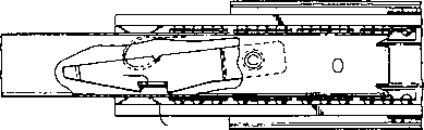
Fig. 3 is the front view that is contained in the bolt device of the present invention in the drawer runner side view, has the deflected position of representing with imaginary line of bar and the stop position of guide rail;
Fig. 4 represents to take from the cross sectional view of bolt device of the 4-4 line of Fig. 3;
Fig. 5 is the disengagement latch front view of representing with imaginary line of throwing off the deformation position of bolt device under impact load that has of the present invention;
Fig. 6 is illustrated in deformation position and cutaway view that be attached to the bolt device that has the Fig. 3 on guide pad and the interconnective sliding members of another sliding members; And
Fig. 7 is that Fig. 2 is the front view of another embodiment.
The specific embodiment
The present invention, bolt device 100 is thrown off in vibration damping locking, shown in Fig. 2 to 6.Identical label is represented like parts in the drawings.Throwing off bolt device 100 preferably is fixed on vertical elongated slot 14 of drawer runner 10.Vertically elongated slot 14 comprises top and bottom slideway retainer 12 and 16, separates with the chute width of any hope.The width of groove 14 approximates the width of the disengagement bolt device 100 of malcompression greatly.
Throw off bolt device 100 and comprise the bars 122 that flatly are parallel to slideway retainer 12 and 16 extensions.This bar comprises a upswept usually antetheca 123 that extends towards slideway retainer 12.Locking brake 104 forms in bar and comprises antetheca 105, rear wall 107 and diapire 109.Rear wall 118 to declivity is connected to a bridge portion 116 and rear portion 110 with bar and brake.Rear portion 110 comprises the feather edge 128 of a common level and integrally constitutes with bridge and bar.In the time of when bolt device is packed groove 14 into its normal position in, retainer 12 abutment surfaces 123 and 118 top 120.And retainer 16 in abutting connection with the rear portion 110 edge 128.
Brake 104 is locked at as Fig. 3 drawer runner 10 by on the steady job position shown in the imaginary line position 500 of guide rail 414.Guide rail 414 comprises guide pad 46 (see figure 6)s that are placed on the guide rail inner surface.Guide rail and guide pad comprise that the groove 416 of a rivet (417) is so that be fixed on guide pad on the guide rail securely.Guide pad 46 comprises a stop column 48, and this stop column extends in the brake 104 so that drawer runner is locked at operating position 500.Perhaps, metal retention pin can form in guide rail to replace the layout of guide pad and stop column.
When throwing off bolt device 100 when being moved to its locked position, the wall 107 of brake when drawer is being opened will in conjunction with and stop and being close to pillar 48.Wall 107 prevents that drawer is drawn out from guide rail.When pulling out drawer, pillar will begin to combine, be bent downwardly bar with contiguous inclined-plane 123 and reach pillar 48, combination with it until brake, and the while bar bounces back into its normal operation position while wall 107 and contacts with pillar 48.Pillar 48 also will contact and stop lives wall 105 to prevent that drawer from being closed accidentally, therefore drawer is remained on the operating position.Therefore, brake has stopped the motion path of throwing off latch and latch dress drawer runner 10 thereon with combining of stop pillar 48.
For drawer runner 10 is discharged from the operating position so as from guide rail mobile drawer, throw off bolt device so that brake 104 does not contact with pillar 48 and makes drawer runner 10 move past guide pad 46 by finger pressurization deflection downwards manually.This slipway location is represented as shown in Figure 6 and by the solid line position of Fig. 3 middle guide 414.As what see at Fig. 6 midship section, the bolt device band and visiblely in the pillar back brake 104 of angled wall 118 and pillar front is arranged by stop pillar 48 in this position.
When throwing off latch with finger pressure when being pressed onto position 200, shown in imaginary line among Fig. 3, bolt rods 122 are thrown off in the contiguous and/or contact of ground way retainer 16.The edge 128 at rear portion holds on retainer 16 and provides leverage downwards for catch bar 122.Brake 104 leaves pillar 48 so that the slideway 10 of drawer is moved then.
For discharging drawer runner 10 from the operating position, can push away manually vertically that the stop pillar makes it to be close to wall 105 and downwards enough to defeat groove 106, to force bar 122 to allow stop pillars 48 to shift out brake 104 with the withdrawal drawer.Though brake 104 prevents drawer runner 10 accidental withdrawals, owing to affact the enough power (about 4.54 kilograms/10 pounds) on the bolt device, drawer can be withdrawn into storage location.
Throw off bolt device 100 and preferably use securing member 114 to be fixed on vertical elongated slot 14, as rivet or integrally formed annulus, bolt device is fixed on protrusion pillar in the ring groove 112.Fig. 4 represents to hold the cutaway view of the groove 112 of rivet 114.Groove surrounds rivet so throws off bolt device and is fixed in the pod by the rivet by a mating holes 122 in latch and the groove.
Promote to reduce impact noise by the vertical channel 106 that is provided with along the drawer runner longitudinal axis and 108.And the best end formation with arc normally vertical of each groove 106 with 108.Groove is made the shape of similar keyhole, thereby preferably the end of the aperture efficiency bending of each groove is wide.Groove 108 has the bent back ends of comparison near retainer 16, and groove 106 has the bent back ends of comparison near retainer 12.The orientation of two grooves is preferably relative, and simultaneously, for rivet 114, groove 108 is near-ends longitudinally, and groove 106 is far-ends longitudinally.Therefore two grooves are by placing the bridge portion 116 between two grooves to separate.
The impact energy of using at least one vertical channel to come absorption brake 104 to contact and producing with stop pillar 48.Under the shock loading of two horizontal directions 300, as shown in Figure 5, proximal edge 124 horizontal ground motions of the bridge 116 of adjacent channels 108, this motion laterally makes groove 108 narrow down or is broadening according to the drawer travel direction.The remote edge 126 of the bridge of adjacent channels 106 is horizontal ground motion also, and this motion is according to compression of drawer travel direction or expansion slot 106.
Same when presses lever 122, first vertical channel, 108 grooves are to expansion and second vertical channel, 106 transverse compression.
The present invention can put into practice with different embodiment and modification.For example, the number of groove can change and still guarantee the deflection of bolt device.Perhaps, as shown in Figure 7, can put deep floor 111 so that the drag to the deflection in using to be provided in groove 106, heavily loaded bolt device will be favourable in this application.Can in groove 106 or 108, place deep floor 111 so that additional drag to be provided.Though groove must be vertical, it can be placed in a plurality of positions along the longitudinal axis of pod.Groove can be made difformity; Need not to adopt keyhole or round end shape.For example, groove can have triangle.Therefore the present invention can be adapted to the slideway assembly of different size and can join with the sliding members of different shape.The meaning and the scope of all and claim equivalence all are in the scope of the present invention with interior variation.This embodiment of the present invention should think and describes in every respect rather than limit; Scope of the present invention is shown by claims rather than the description of front.
Claims (17)
1. bolt device is thrown off in the locking of a slideway assembly, and this slideway assembly comprises at least one elongated slot and guide rail, throws off bolt device and comprises the whole combination that constitutes:
Therefore releasedly the slideway assembly is fixed on the operating position and prevents the integral stop apparatus of the further stretching, extension or the withdrawal of described elongated slot;
Make and throw off the bolt device deflection so that the slideway assembly is stretched over the operating position and absorbs when described elongated slot stops and being close to first device of the impact energy that brake gear produces; And
Make and throw off the bolt device deflection so that the slideway assembly installs from second of operating position withdrawal.
2. bolt device is thrown off in locking as claimed in claim 1, it is characterized in that: the inclined surface and at least one vertical channel on the bolt device behind the brake gear that are included in described brake gear front for first device that the slideway assembly is stretched over the operating position.
3. bolt device is thrown off in locking as claimed in claim 1, and it is characterized in that: described second device comprises at least one vertical channel.
4. bolt device is thrown off in locking as claimed in claim 3, and it is characterized in that: described vertical channel is laterally compressible.
5. bolt device is thrown off in locking as claimed in claim 3, and it is characterized in that: described vertical channel is laterally extendible.
6. bolt device is thrown off in locking as claimed in claim 1, it is characterized in that: described first device further comprises two grooves relative, that vertically separate.
7. bolt device is thrown off in locking as claimed in claim 6, it is characterized in that: described two vertical channel are separated and at relative direction opening, and one of them groove face upwards and another faces down.
8. bolt device is thrown off in locking as claimed in claim 6, it is characterized in that; One of them groove comprises a deep floor.
9. slideway assembly comprises:
The drawer runner that at least one slides in guide rail; And
Bolt device is thrown off in a locking, comprise one for the integral stop apparatus that drawer runner stopped at the operating position in the guide rail, withdraw unintentionally or from guide rail, throw off and make to retracted position and throw off the bolt device deflection, and absorb the bending device of the impact energy of generation when drawer runner combines with brake gear for discharge this drawer runner from the operating position to prevent this drawer runner.
10. slideway assembly as claimed in claim 9, it is characterized in that: also comprise erecting device, this erecting device comprises drawer runner and the groove in throwing off bolt device, and the securing member in this groove, and this securing member will be thrown off bolt device and is fixed on the drawer runner.
11. slideway assembly as claimed in claim 9 is characterized in that: for the brake gear that the slideway assembly is stopped at the operating position comprises a brake that constitutes and one the pillar on the guide rail of being received in for the locking brake in the bolt device upper surface.
12. slideway assembly bolt device as claimed in claim 9, it is characterized in that: this bending device comprises at least one vertical channel.
13. the slideway assembly bolt device as claim 12 is characterized in that: this vertical channel is laterally compressible.
14. the slideway assembly bolt device as claim 12 is characterized in that: this vertical channel is laterally extendible.
15. slideway assembly as claimed in claim 9 is characterized in that: this bending device comprises two relative, separated vertical channel.
16. the slideway assembly as claim 15 is characterized in that: these two vertical channel are separated and in relative direction, and one of them groove face upwards and another faces down.
17. bolt device is thrown off in the locking as claim 15, it is characterized in that: a groove comprises a deep floor.
Applications Claiming Priority (2)
| Application Number | Priority Date | Filing Date | Title |
|---|---|---|---|
| US08/649,453 | 1996-05-17 | ||
| US08/649,453 US5730514A (en) | 1996-05-17 | 1996-05-17 | Shock absorbing locking disconnect latch for ball bearing slides |
Publications (2)
| Publication Number | Publication Date |
|---|---|
| CN1219111A CN1219111A (en) | 1999-06-09 |
| CN1135085C true CN1135085C (en) | 2004-01-21 |
Family
ID=24604854
Family Applications (1)
| Application Number | Title | Priority Date | Filing Date |
|---|---|---|---|
| CNB971947252A Expired - Fee Related CN1135085C (en) | 1996-05-17 | 1997-05-15 | Shock absorbing locking discoment latch for ball bearing slides |
Country Status (9)
| Country | Link |
|---|---|
| US (1) | US5730514A (en) |
| EP (1) | EP0955844B1 (en) |
| JP (1) | JP3483034B2 (en) |
| CN (1) | CN1135085C (en) |
| CA (1) | CA2255069C (en) |
| DE (1) | DE69736437T2 (en) |
| ES (1) | ES2268729T3 (en) |
| TW (1) | TW409528U (en) |
| WO (1) | WO1997042857A1 (en) |
Families Citing this family (51)
| Publication number | Priority date | Publication date | Assignee | Title |
|---|---|---|---|---|
| AT3164U1 (en) * | 1998-11-04 | 1999-11-25 | Fulterer Gmbh | SIDE GUIDE FOR HIGH CABINET EXTENSIONS |
| US6209979B1 (en) | 2000-02-22 | 2001-04-03 | General Devices Co., Ltd. | Telescoping slide with quick-mount system |
| US6971729B1 (en) | 2000-05-01 | 2005-12-06 | Accuride International, Inc. | Self-closing slide |
| DE60107558T2 (en) | 2000-05-01 | 2005-12-15 | Accuride International Inc., Santa Fe Springs | SELF-CLOSING EXTRACTOR AND ASSOCIATED DEVICE |
| US20060082266A1 (en) * | 2000-05-01 | 2006-04-20 | Le Hai D | Self-moving slides and self-moving mechanisms |
| US6435636B1 (en) | 2000-06-15 | 2002-08-20 | Compx International Inc. | Drawer slide cushion end stop bumper construction |
| US6817685B2 (en) | 2000-08-08 | 2004-11-16 | Accuride International Inc. | Release mechanism for drawer slide latches |
| WO2002039850A2 (en) * | 2000-11-16 | 2002-05-23 | Accuride International Inc. | Friction drawer slide |
| US6554379B2 (en) | 2001-02-16 | 2003-04-29 | Central Industrial Supply Company, Inc. | Slide rail assembly with front release |
| WO2002067724A1 (en) * | 2001-02-28 | 2002-09-06 | Accuride International Inc. | Snap-in latch |
| US6883885B2 (en) | 2001-12-19 | 2005-04-26 | Jonathan Manufacturing Corporation | Front release for a slide assembly |
| US6749275B2 (en) * | 2002-06-21 | 2004-06-15 | General Devices Co., Inc. | Quick-mount support system for telescoping slide |
| US6601933B1 (en) | 2002-06-21 | 2003-08-05 | General Devices Co., Inc. | Telescoping slide with quick-mount system |
| WO2004000078A1 (en) * | 2002-06-21 | 2003-12-31 | General Devices Co., Inc. | Quick-mount support system for telescoping slide |
| DE10228670A1 (en) * | 2002-06-27 | 2004-01-22 | Westfalia Profiltechnik Gmbh & Co. Kg | Guiding and running system of drawers, pull-outs for tool trolleys or the like |
| AU2003263887A1 (en) * | 2002-08-15 | 2004-03-03 | General Devices Co., Inc. | Support system for telescoping slide assembly |
| US7029080B2 (en) | 2002-09-25 | 2006-04-18 | Central Industrial Supply Company | Slide rail having front release latch |
| US6851774B2 (en) * | 2003-03-06 | 2005-02-08 | King Slide Works Co., Ltd. | Retaining structure for a track device for drawers |
| US20050017613A1 (en) * | 2003-06-23 | 2005-01-27 | Paul Cirocco | Front-release lock arrangement for slide assembly |
| US7104691B2 (en) * | 2003-07-31 | 2006-09-12 | Accuride International, Inc. | Self-moving slide, mechanism for self-moving slide and method for self-moving a slide |
| US7604307B2 (en) * | 2003-10-24 | 2009-10-20 | General Devices Co., Inc. | Telescoping slide assembly with quick-mount keyhole lock system |
| US6955380B1 (en) | 2003-11-14 | 2005-10-18 | Sebastian Barr | Drawer safety latch |
| US6935711B1 (en) | 2004-02-26 | 2005-08-30 | General Devices Co., Inc. | Latch mover for quick-mount support for telescoping slide |
| US6929339B1 (en) * | 2004-02-26 | 2005-08-16 | General Devices Co., Inc. | Latch controller for quick-mount support for telescoping slide |
| US6957878B2 (en) * | 2004-02-26 | 2005-10-25 | General Devices Co., Inc. | Latch mover for quick-mount telescoping slide support system |
| US20050229360A1 (en) * | 2004-04-15 | 2005-10-20 | Lowe Mark J | Hinge |
| US20050242692A1 (en) * | 2004-04-30 | 2005-11-03 | Nan Juen International Co., Ltd. | Slide bumper for drawer |
| US7156477B1 (en) * | 2004-06-09 | 2007-01-02 | Chun-Min Lu | Release-control stop member of a sliding rail assembly for drawer |
| US20060033408A1 (en) * | 2004-08-11 | 2006-02-16 | Nan Juen International Co., Ltd. | Extended rod of slide mechanism for drawer slide track |
| US7101081B2 (en) * | 2004-10-12 | 2006-09-05 | King Slide Works Co., Ltd. | Positioning device for a ball bearing slide |
| CN101384193B (en) * | 2004-11-05 | 2010-12-08 | 艾库里德国际有限公司 | Self-moving mechanism and slide incorporating the same |
| JP4782795B2 (en) * | 2004-11-05 | 2011-09-28 | アキュライド インターナショナル,インコーポレイテッド | Braking mechanism and slide incorporating the same |
| US7494101B2 (en) * | 2005-08-18 | 2009-02-24 | Protrend Co., Ltd | Hook-on type rail |
| US7533946B2 (en) * | 2005-08-25 | 2009-05-19 | Knape & Vogt Manufacturing Company | Closing device for drawers |
| US7481504B2 (en) * | 2005-11-23 | 2009-01-27 | King Slide Works Co., Ltd. | Mount latch structure for a telescoping slide |
| US7604309B2 (en) * | 2006-01-19 | 2009-10-20 | King Slide Works Co., Ltd. | Auto release retaining mechanism of a slide |
| US20080012456A1 (en) * | 2006-06-06 | 2008-01-17 | Judge Ronald J | Server cabinet with slide assembly |
| US20080018213A1 (en) * | 2006-07-20 | 2008-01-24 | Ken-Ching Chen | Drawer slide assembly having an adjustment mechanism |
| US8419080B2 (en) * | 2007-02-09 | 2013-04-16 | Bruce Levine | Drawer safety latch |
| CN201048713Y (en) * | 2007-06-07 | 2008-04-23 | 鸿富锦精密工业(深圳)有限公司 | Sliding rail device |
| US8056989B2 (en) * | 2007-09-10 | 2011-11-15 | Zielinski Randall S | Child-proof safety latch |
| JP5224519B2 (en) * | 2008-09-30 | 2013-07-03 | Thk株式会社 | Exercise guidance device |
| US8757458B2 (en) * | 2009-05-29 | 2014-06-24 | Lippert Components, Inc. | Storage box with slide out storage tray |
| US20100301721A1 (en) * | 2009-05-29 | 2010-12-02 | Nebel Michael W | Storage box with slide out storage tray |
| US8439459B2 (en) | 2010-11-29 | 2013-05-14 | Lockheed Martin Corporation | Apparatus for latching a drawer using a cam latch |
| US8485616B2 (en) | 2011-02-09 | 2013-07-16 | King Slide Works Co., Ltd. | Slide assembly with buffering member for reducing impact and noise |
| US9131622B2 (en) * | 2011-06-03 | 2015-09-08 | Middle Atlantic Products, Inc. | Rack rail locking lever |
| DE102013102944A1 (en) | 2012-10-12 | 2014-06-18 | Paul Hettich Gmbh & Co. Kg | pull-out guide |
| TWM495781U (en) | 2014-11-28 | 2015-02-21 | Sun Chain Trading Co Ltd | Front connection device of concealed sliding rail |
| DE202015104439U1 (en) * | 2015-08-21 | 2016-11-22 | Grass Gmbh | Device for moving a movable furniture part and furniture |
| CN105496047B (en) * | 2016-01-08 | 2017-10-24 | 平湖市陈达仓储办公设备有限公司 | A kind of drawout cubicle |
Family Cites Families (6)
| Publication number | Priority date | Publication date | Assignee | Title |
|---|---|---|---|---|
| US4401350A (en) * | 1981-05-01 | 1983-08-30 | Fortune William S | Modular storage system |
| US4423914A (en) * | 1981-05-18 | 1984-01-03 | Knape & Vogt Manufacturing Co. | Drawer slide locking lever |
| US4560212A (en) * | 1983-10-07 | 1985-12-24 | Standard Precision, Inc. | Three part ball bearing slide with lockable intermediate slide member |
| US4549773A (en) * | 1983-10-07 | 1985-10-29 | Standard Precision, Inc. | Ball bearing slide with removable and lockable inner slide member |
| US5255983A (en) * | 1992-07-28 | 1993-10-26 | Accuride International, Inc. | Shock absorbing disconnect latch for ball bearing slides |
| US5542759A (en) * | 1995-04-27 | 1996-08-06 | Snap-On Technologies, Inc. | Shock absorbing disconnect latch for drawer slides |
-
1996
- 1996-05-17 US US08/649,453 patent/US5730514A/en not_active Expired - Lifetime
-
1997
- 1997-05-15 JP JP54116397A patent/JP3483034B2/en not_active Expired - Fee Related
- 1997-05-15 WO PCT/US1997/008429 patent/WO1997042857A1/en active IP Right Grant
- 1997-05-15 EP EP97925632A patent/EP0955844B1/en not_active Expired - Lifetime
- 1997-05-15 CA CA002255069A patent/CA2255069C/en not_active Expired - Fee Related
- 1997-05-15 ES ES97925632T patent/ES2268729T3/en not_active Expired - Lifetime
- 1997-05-15 DE DE69736437T patent/DE69736437T2/en not_active Expired - Fee Related
- 1997-05-15 CN CNB971947252A patent/CN1135085C/en not_active Expired - Fee Related
- 1997-05-16 TW TW089202514U patent/TW409528U/en not_active IP Right Cessation
Also Published As
| Publication number | Publication date |
|---|---|
| CA2255069C (en) | 2002-11-12 |
| EP0955844A1 (en) | 1999-11-17 |
| JPH11511678A (en) | 1999-10-12 |
| EP0955844B1 (en) | 2006-08-02 |
| US5730514A (en) | 1998-03-24 |
| EP0955844A4 (en) | 2002-11-27 |
| DE69736437D1 (en) | 2006-09-14 |
| CN1219111A (en) | 1999-06-09 |
| DE69736437T2 (en) | 2006-12-07 |
| ES2268729T3 (en) | 2007-03-16 |
| TW409528U (en) | 2000-10-21 |
| WO1997042857A1 (en) | 1997-11-20 |
| CA2255069A1 (en) | 1997-11-20 |
| JP3483034B2 (en) | 2004-01-06 |
Similar Documents
| Publication | Publication Date | Title |
|---|---|---|
| CN1135085C (en) | Shock absorbing locking discoment latch for ball bearing slides | |
| US7240978B2 (en) | Sliding assisting device | |
| US7144092B1 (en) | Arresting apparatus of multilayer drawers | |
| EP1816927B1 (en) | Opening device for drawers | |
| US7967399B1 (en) | Linearly actuated chassis lock for a drawer slide | |
| CN107130402B (en) | Pushing spring lock and washing machine | |
| CN101784212A (en) | Self closing mechanism for drawer slides | |
| CN107142684B (en) | Push-spring type detergent box and washing machine | |
| US8632142B2 (en) | Undermount-type sliding apparatus equipped with automatic closing device | |
| CN107254763B (en) | Push-spring type detergent box and washing machine | |
| CN107142685B (en) | Push-spring type detergent box and washing machine | |
| CN107287836B (en) | Push-spring type detergent box and washing machine | |
| EP2592966B1 (en) | Pull-out guide for drawers | |
| CN1133387C (en) | Cupboard with safety stopping device | |
| CN107287835B (en) | Push-spring type detergent box and washing machine | |
| CN219762839U (en) | Bearing forced pushing protection device for buffering rebound synchronizer | |
| KR102579038B1 (en) | Drawer assembly | |
| KR20100108795A (en) | Structure for installing drawer | |
| CN116391982A (en) | Bearing forced pushing protection device for buffering rebound synchronizer | |
| CN215983503U (en) | Automatic door opening device and refrigerator | |
| CN220312702U (en) | Telescopic steel plate shield | |
| CN215113468U (en) | Double-push-rod door opening device for household appliances and double-door refrigerator | |
| CN216277446U (en) | Automatic door opening device for double-door household appliance | |
| CN218127337U (en) | Luggage case pull rod | |
| CN116537649A (en) | Quick-opening anti-theft lock |
Legal Events
| Date | Code | Title | Description |
|---|---|---|---|
| C06 | Publication | ||
| PB01 | Publication | ||
| C10 | Entry into substantive examination | ||
| SE01 | Entry into force of request for substantive examination | ||
| C14 | Grant of patent or utility model | ||
| GR01 | Patent grant | ||
| C17 | Cessation of patent right | ||
| CF01 | Termination of patent right due to non-payment of annual fee |
Granted publication date: 20040121 Termination date: 20110515 |