CN113493032A - Blanking type handbag packaging machine - Google Patents
Blanking type handbag packaging machine Download PDFInfo
- Publication number
- CN113493032A CN113493032A CN202011364082.XA CN202011364082A CN113493032A CN 113493032 A CN113493032 A CN 113493032A CN 202011364082 A CN202011364082 A CN 202011364082A CN 113493032 A CN113493032 A CN 113493032A
- Authority
- CN
- China
- Prior art keywords
- bag
- feeding
- fixed
- cylinder
- plate
- Prior art date
- Legal status (The legal status is an assumption and is not a legal conclusion. Google has not performed a legal analysis and makes no representation as to the accuracy of the status listed.)
- Pending
Links
Images


Classifications
-
- B—PERFORMING OPERATIONS; TRANSPORTING
- B65—CONVEYING; PACKING; STORING; HANDLING THIN OR FILAMENTARY MATERIAL
- B65B—MACHINES, APPARATUS OR DEVICES FOR, OR METHODS OF, PACKAGING ARTICLES OR MATERIALS; UNPACKING
- B65B59/00—Arrangements to enable machines to handle articles of different sizes, to produce packages of different sizes, to vary the contents of packages, to handle different types of packaging material, or to give access for cleaning or maintenance purposes
- B65B59/001—Arrangements to enable adjustments related to the product to be packaged
-
- B—PERFORMING OPERATIONS; TRANSPORTING
- B65—CONVEYING; PACKING; STORING; HANDLING THIN OR FILAMENTARY MATERIAL
- B65B—MACHINES, APPARATUS OR DEVICES FOR, OR METHODS OF, PACKAGING ARTICLES OR MATERIALS; UNPACKING
- B65B19/00—Packaging rod-shaped or tubular articles susceptible to damage by abrasion or pressure, e.g. cigarettes, cigars, macaroni, spaghetti, drinking straws or welding electrodes
- B65B19/34—Packaging other rod-shaped articles, e.g. sausages, macaroni, spaghetti, drinking straws, welding electrodes
-
- B—PERFORMING OPERATIONS; TRANSPORTING
- B65—CONVEYING; PACKING; STORING; HANDLING THIN OR FILAMENTARY MATERIAL
- B65B—MACHINES, APPARATUS OR DEVICES FOR, OR METHODS OF, PACKAGING ARTICLES OR MATERIALS; UNPACKING
- B65B35/00—Supplying, feeding, arranging or orientating articles to be packaged
- B65B35/02—Supply magazines
-
- B—PERFORMING OPERATIONS; TRANSPORTING
- B65—CONVEYING; PACKING; STORING; HANDLING THIN OR FILAMENTARY MATERIAL
- B65B—MACHINES, APPARATUS OR DEVICES FOR, OR METHODS OF, PACKAGING ARTICLES OR MATERIALS; UNPACKING
- B65B35/00—Supplying, feeding, arranging or orientating articles to be packaged
- B65B35/10—Feeding, e.g. conveying, single articles
- B65B35/20—Feeding, e.g. conveying, single articles by reciprocating or oscillatory pushers
-
- B—PERFORMING OPERATIONS; TRANSPORTING
- B65—CONVEYING; PACKING; STORING; HANDLING THIN OR FILAMENTARY MATERIAL
- B65B—MACHINES, APPARATUS OR DEVICES FOR, OR METHODS OF, PACKAGING ARTICLES OR MATERIALS; UNPACKING
- B65B43/00—Forming, feeding, opening or setting-up containers or receptacles in association with packaging
- B65B43/26—Opening or distending bags; Opening, erecting, or setting-up boxes, cartons, or carton blanks
-
- B—PERFORMING OPERATIONS; TRANSPORTING
- B65—CONVEYING; PACKING; STORING; HANDLING THIN OR FILAMENTARY MATERIAL
- B65B—MACHINES, APPARATUS OR DEVICES FOR, OR METHODS OF, PACKAGING ARTICLES OR MATERIALS; UNPACKING
- B65B51/00—Devices for, or methods of, sealing or securing package folds or closures; Devices for gathering or twisting wrappers, or necks of bags
- B65B51/10—Applying or generating heat or pressure or combinations thereof
- B65B51/14—Applying or generating heat or pressure or combinations thereof by reciprocating or oscillating members
- B65B51/146—Closing bags
-
- B—PERFORMING OPERATIONS; TRANSPORTING
- B65—CONVEYING; PACKING; STORING; HANDLING THIN OR FILAMENTARY MATERIAL
- B65B—MACHINES, APPARATUS OR DEVICES FOR, OR METHODS OF, PACKAGING ARTICLES OR MATERIALS; UNPACKING
- B65B57/00—Automatic control, checking, warning, or safety devices
- B65B57/10—Automatic control, checking, warning, or safety devices responsive to absence, presence, abnormal feed, or misplacement of articles or materials to be packaged
- B65B57/14—Automatic control, checking, warning, or safety devices responsive to absence, presence, abnormal feed, or misplacement of articles or materials to be packaged and operating to control, or stop, the feed of articles or material to be packaged
-
- B—PERFORMING OPERATIONS; TRANSPORTING
- B65—CONVEYING; PACKING; STORING; HANDLING THIN OR FILAMENTARY MATERIAL
- B65B—MACHINES, APPARATUS OR DEVICES FOR, OR METHODS OF, PACKAGING ARTICLES OR MATERIALS; UNPACKING
- B65B59/00—Arrangements to enable machines to handle articles of different sizes, to produce packages of different sizes, to vary the contents of packages, to handle different types of packaging material, or to give access for cleaning or maintenance purposes
- B65B59/003—Arrangements to enable adjustments related to the packaging material
-
- B—PERFORMING OPERATIONS; TRANSPORTING
- B65—CONVEYING; PACKING; STORING; HANDLING THIN OR FILAMENTARY MATERIAL
- B65B—MACHINES, APPARATUS OR DEVICES FOR, OR METHODS OF, PACKAGING ARTICLES OR MATERIALS; UNPACKING
- B65B63/00—Auxiliary devices, not otherwise provided for, for operating on articles or materials to be packaged
- B65B63/02—Auxiliary devices, not otherwise provided for, for operating on articles or materials to be packaged for compressing or compacting articles or materials prior to wrapping or insertion in containers or receptacles
- B65B63/028—Auxiliary devices, not otherwise provided for, for operating on articles or materials to be packaged for compressing or compacting articles or materials prior to wrapping or insertion in containers or receptacles by pneumatic means
Landscapes
- Engineering & Computer Science (AREA)
- Mechanical Engineering (AREA)
- Supplying Of Containers To The Packaging Station (AREA)
Abstract
A blanking type handbag packaging machine comprises a blanking mechanism, a bag storage and taking mechanism, a bag grabbing and feeding mechanism, a bag storage and blocking mechanism, a bag opening and closing mechanism, a double-station feeding mechanism, a rotary face supporting mechanism and a hot-ironing sealing mechanism which are fixed on a frame structure, wherein the blanking mechanism is integrally installed at the middle upper part of the frame structure; the bag opening and closing mechanism is arranged right below the blanking mechanism; a double-station feeding mechanism is arranged below the bag opening and closing mechanism; the bag storage and taking mechanism is arranged on the left side of the blanking mechanism; the bag grabbing and feeding mechanism and the bag storing and blocking mechanism are both arranged below the bag storing and taking mechanism, and the bag storing and blocking mechanism is positioned in front of the bag grabbing and feeding mechanism; the rotary plane supporting mechanism is arranged below the double-station feeding mechanism; the hot-ironing sealing mechanism is arranged on the right side of the blanking mechanism. The invention has the advantages that: the noodle packaging machine is suitable for packaging noodles with various lengths, and has good working stability and high packaging efficiency.
Description
Technical Field
The invention relates to a blanking type handbag packaging machine which is mainly used for packaging noodles packaged by a handbag with large volume and other similar commodities (a noodle packaging machine in the handbag).
Background
The existing hand bag packing machine industry equipment mostly adopts a combination structure such as a cylinder, the operation stability is poor, the specification replacement adjustment is complicated, and the packing effect is unstable.
Disclosure of Invention
The invention provides a blanking type handbag, which aims to solve the problems in the prior art.
The technical scheme of the invention is as follows: a blanking type portable bag packaging machine is characterized by comprising a blanking mechanism, a bag storage and taking mechanism, a bag grabbing and feeding mechanism, a bag storage and blocking mechanism, a bag opening and closing mechanism, a double-station feeding mechanism, a rotary face supporting mechanism and a hot-stamping sealing mechanism which are fixed on a frame structure, wherein the blanking mechanism is integrally installed at the middle upper part of the frame structure; the bag opening and closing mechanism is arranged right below the blanking mechanism; a double-station feeding mechanism is arranged below the bag opening and closing mechanism; the bag storage and taking mechanism is arranged on the left side of the blanking mechanism; the bag grabbing and feeding mechanism and the bag storing and blocking mechanism are both arranged below the bag storing and taking mechanism, and the bag storing and blocking mechanism is positioned in front of the bag grabbing and feeding mechanism; the rotary plane supporting mechanism is arranged below the double-station feeding mechanism; the hot-ironing sealing mechanism is arranged on the right side of the blanking mechanism.
The invention has the advantages that: the double-layer blanking mechanism is adopted, so that the noodle shaping machine is easy to adjust and is suitable for various noodle lengths, and the blanking speed and stability are improved by the two-layer blanking and synchronous belt noodle pressing; the bag opening and closing mechanism is adopted, so that the bag opening and closing mechanism can adapt to the sizes of various handbag openings, is easy to adjust, and has good bag opening and bagging effects; the double-station feeding mechanism is adopted, so that the safety and reliability are realized, the work is stable and the efficiency is high; the bag storage and taking mechanism is adopted, so that the bag storage and taking mechanism is easy to adjust and is suitable for various different handbag sizes; the bag grabbing and conveying mechanism is simple in structure, good in bag grabbing effect and stable and reliable in work; adopt to deposit a bag and keep off a bag mechanism, deposit a bag effectual, easily snatch and position stable.
Drawings
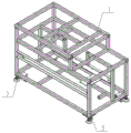
FIG. 1 is a schematic perspective view of the present invention;
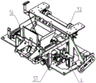
FIG. 2 is a schematic perspective view of the frame mechanism J of the present invention;
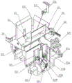
FIG. 3 is a schematic perspective view of the blanking mechanism L of the present invention;
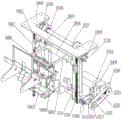
FIG. 4 is an isometric front view of the double hopper blanking portion SL of FIG. 3;
FIG. 5 is a rear isometric view of the double hopper blanking portion SL of FIG. 3;
FIG. 6 is an isometric view of a portion of the screw guide adjustment section ST of FIG. 3 (for adjustment of the upper flush section to accommodate different face lengths; shown with a portion of the double hopper blanking section SL);
FIG. 7 is an isometric view of a portion of the screw guide adjustment portion ST of FIG. 3 (for adjustment of the lower flush surface member to accommodate different face lengths);
FIG. 8 is an isometric view of a portion of the guide rail adjustment portion ST of FIG. 3 (for adjustment to accommodate different bag widths);
FIG. 9 is an isometric view of the simultaneous press face into pocket portion YJ of FIG. 3;
FIG. 10 is a schematic perspective view of the bag opening and closing mechanism CH according to the present invention;
fig. 11 is a schematic perspective view of a main portion of fig. 10;
FIG. 12 is a side elevational schematic view of the frame mechanism of the present invention;
FIG. 13 is a top view of FIG. 12;
FIG. 14 is a left side view of FIG. 12;
FIG. 15 is a schematic side view of the bag opening/clamping mechanism of the present invention;
FIG. 16 is a top view of FIG. 15;
FIG. 17 is a side elevational view of the center seam forming mechanism of the present invention;
FIG. 18 is a top view of FIG. 17;
FIG. 19 is a schematic side view of the bag width adjustment mechanism of the present invention;
FIG. 20 is a top view of FIG. 19;
FIG. 21 is a side view of the lift mechanism of the present invention;
FIG. 22 is a top view of FIG. 21;
fig. 23 is a schematic perspective view of a rotary tray surface mechanism XT according to the present invention;
FIG. 24 is a schematic perspective view of the sealing mechanism RF of the present invention;
FIG. 25 is a schematic structural view of the quick-change silicone gel ironing base and the silicone strip according to the present invention;
FIG. 26 is a schematic perspective view of a bag storage and retrieval mechanism CQ according to the present invention;
fig. 27 is a schematic perspective view of a bag grasping and feeding mechanism ZS according to the present invention;
FIG. 28 is a schematic perspective view of a storage and retaining mechanism CD according to the present invention;
fig. 29 is a schematic perspective view of the double-station feeding mechanism SS of the present invention.
Detailed Description
Referring to fig. 1, the present invention relates to a blanking type handbag packing machine, comprising: the automatic bag opening and closing machine comprises a blanking mechanism L, a bag storage and taking mechanism CQ, a bag grabbing and sending mechanism ZS, a bag storage and blocking mechanism CD, a bag opening and closing mechanism CH, a double-station feeding mechanism SS, a rotary plane supporting mechanism XT and a hot-ironing sealing mechanism RF which are fixed on a rack structure J through bolts, wherein the blanking mechanism L is integrally installed at the middle upper part of the rack structure J, and the upper part of the blanking mechanism L corresponds to an outlet of a lifting machine C (the lifting machine C is mainly used for providing weighed materials such as fine dried noodles for the packaging machine and does not belong to the patent); the bag opening and closing mechanism CH is arranged right below the blanking mechanism L; a double-station feeding mechanism SS is arranged below the bag opening and closing mechanism CH; the bag storage and taking mechanism CQ is arranged on the left side of the blanking mechanism L; the bag grabbing and feeding mechanism ZS and the bag storing and blocking mechanism CD are both arranged below the bag storing and taking mechanism CQ, and the bag storing and blocking mechanism CD is positioned in front of the bag grabbing and feeding mechanism ZS; the rotary plane supporting mechanism XT is arranged below the double-station feeding mechanism SS; the hot stamping sealing mechanism RF is arranged on the right side of the blanking mechanism L.
The bag grabbing and feeding mechanism ZS is used for feeding a handbag taken out by the bag storing and taking mechanism CQ to the bag storing and blocking mechanism CD, the bag storing and blocking mechanism CD is mainly used for temporarily storing the handbag to wait for clamping by the double-station feeding mechanism SS, the double-station feeding mechanism SS finishes actions including grabbing the handbag, conveying the handbag to the bag opening and closing mechanism CH, conveying the handbag filled with materials to the hot-pressing sealing mechanism RF, the rotary face supporting mechanism XT is used for arranging the materials in the packing bag to be convenient for clamping and sealing, the bag opening and closing mechanism CH is mainly used for supporting and receiving the material of the packing bag, folding the packing bag into an M shape after the completion of the material is convenient for sealing, and the hot-pressing sealing mechanism RF mainly clamps and seals the bag opening by heating the hot-melting of the packing bag opening.
The output belt a in fig. 1 is an auxiliary device, is not a component of the present invention, is arranged right below the blanching seal mechanism RF of the present invention, and is installed on the frame 1. The materials falling down by the hand bag packing machine directly fall down on the belt and are conveyed out.
Referring to fig. 2, the frame structure J includes: frame 1, lower margin 2 and truckle 3, a plurality of lower margins 2 and truckle 3 are installed in the bottom of frame 1.
Referring to fig. 3-9, the blanking mechanism L adopts a double-layer blanking mechanism, the overall structure of the double-layer blanking mechanism is as shown in fig. 1, and the double-layer blanking mechanism comprises a frame body S1, a double-layer hopper blanking portion SL, a screw guide rail adjusting portion ST and a synchronous surface pressing and bag feeding portion YJ, the double-layer hopper blanking portion SL is located at a position near the front of the middle of the frame body 1 and is fixed on a frame body S1 through bolts, and the frame body S1 is installed on a frame structure J; the screw guide rail adjusting part ST is positioned at the left side and the right side of the double-layer hopper blanking part SL and is respectively connected with the double-layer hopper blanking part SL through bolts; the synchronous dough pressing and bag feeding part YJ is fixed on the frame body S1 through bolts and is positioned behind the blanking part SL of the double-layer hopper.
Referring to fig. 4 and 5, the double-layer hopper blanking portion SL includes: an upper guide rail S2, a connecting plate S3, a front bent plate S4, a front baffle S5, a rear bent plate S6, a rear baffle S7, an upper holding surface cylinder S8, an upper holding surface plate S9, a fixed shaft sleeve S10, an upper blanking plate swing arm S11, an upper blanking cylinder S12, an upper joint bearing S13, a support shaft S14, a lower guide rail S15, a fixed plate S16, a support plate S17, a cylinder block S18, a lower blanking cylinder S19, a lower knuckle bearing S20, a sleeve seat S21, a front blanking plate S22, a lower support seat S23, a right baffle S24, a left baffle S25, a rear plate S26, a triaxial cylinder block S27, a lower holding surface plate S27, a photoelectric support S27, an upper photoelectric S27, a lower photoelectric S27, an upper baffle S27, a lower cylinder S27, an upper cylinder block S27, a lower cylinder S27 and a lower cylinder S27.
The connection relation among the SL parts of the blanking part of the double-layer hopper is as follows:
the upper guide rail S2 and the lower guide rail S15 are fixedly connected with the frame body S1 through bolts, the upper side of the front baffle S5 is connected with the front bent plate S4 through bolts, the front bent plate S4 and the connecting plate S3 are fixed on the sliding block of the upper guide rail S2, the lower side of the front baffle S5 is fixed on the supporting plate S17, and the two ends of the supporting plate S17 are connected with the sliding block of the lower guide rail S15 through fixing plates S16; the left side and the right side of the rear baffle S7 are fixed on the other slide block on the guide rail S2 through a rear bent plate S6, and the front baffle S5 and the rear baffle S7 are arranged in a front-rear opposite mode; the pop-up surface cylinder S8 is fixed on the front baffle S5 through a bolt, and the pop-up surface plate S9 is fixed on a piston rod of the pop-up surface cylinder S8; two sides of the lower part of the front baffle S5 are respectively provided with a supporting arm 501 extending forwards, a fixed shaft sleeve S10 is rotatably supported between the two supporting arms 501, one end of an upper blanking plate swing arm S11 is respectively connected to the two ends of the fixed shaft sleeve S10 close to the two ends, and an upper blanking plate is connected between the other ends (free ends capable of swinging) of the two upper blanking plate swing arms S11; a support shaft S14 is fixedly supported between the two upper blanking plate swing arms S11; the bottom end of an upper blanking cylinder S12 is hinged on the front side of the lower part of the front baffle S5, a piston rod of the upper blanking cylinder S12 is connected with a supporting shaft S14 through an upper joint bearing S13, and the supporting shaft S14 is driven to rotate through the expansion of the piston rod of the upper blanking cylinder S12, so that the blocking surface action of the blanking plate is realized; a cylinder seat S18 is connected to the lower surface of the supporting plate S17, a lower blanking cylinder S19 is hinged to the cylinder seat S18, and a piston rod of the blanking cylinder S19 faces to the front end; a small shaft rotatably supporting the two ends of the upper edge of the front plate S22 through a sleeve seat S21 is arranged between the two sides of the front end of the bottom of the front baffle S5, and a piston rod of the blanking cylinder S19 is hinged with a convex seat (swing arm) arranged in the middle of the upper edge of the front plate S22 through a lower knuckle bearing S20; one end of the lower support seat S23 is slidably mounted at the rear of the lower guide rail S15 through a slider, and the bottom ends of the right baffle plate S24 and the left baffle plate S25 are respectively fixed on the lower support seat S23; a small shaft at two ends of the upper edge of the rear plate S26 is rotatably supported between the far ends of the lower edges of the right baffle plate S24 and the left baffle plate S25 through a shaft sleeve, a convex seat is also arranged at the middle part of the upper edge of the rear plate S26, and a piston rod of another lower blanking cylinder S19 is hinged with the convex seat at the middle part of the upper edge of the rear plate S26 through another lower knuckle bearing S20 (the two lower blanking cylinders S19 have the same function and are used for respectively opening the front plate S22 and the rear plate S26); the bottom end of the blanking cylinder S19 is hinged on the right baffle S24; a triaxial cylinder S28 is arranged on the lower supporting seat S23 through a triaxial cylinder seat S27, a lower supporting panel S29 is arranged on a piston rod of the triaxial cylinder S28, and the lower supporting panel S29 is positioned between the right baffle S24 and the left baffle S25; an upper photoelectric S31 is arranged above the upper guide rail S2, an upper photoelectric S31 is fixed on a photoelectric bracket S30, and the photoelectric bracket S30 is fixed on a hoist C or other matched equipment; a lower photoelectric S32 is arranged behind the left baffle S25; an upper baffle plate S33 and a lower baffle plate S34 are provided on right upper and lower portions of the front baffle plate S5 and the rear baffle plate S7, the upper baffle plate S33 is connected to a piston rod of an upper flush cylinder S39 (the upper baffle plate S33 and the upper flush cylinder S39 are upper flush members), the upper flush cylinder S39 is fixed to an upper cylinder block S38 by bolts, and the upper cylinder block S38 is mounted on a relevant member of the screw rail adjusting portion ST (see the description of fig. 6 to 8 below for specific connection); the lower baffle S34 is fixed to a piston rod of a lower flush cylinder S46 (the lower baffle S34 and the lower flush cylinder S46 are lower flush members) by bolts, the lower flush cylinder S46 is fixed to a lower cylinder mount S45, and a lower cylinder mount S45 is mounted to a related part of the screw rail adjusting portion ST (see the following description of fig. 4 to 6).
Referring to fig. 6 to 8, the lead screw rail adjusting part ST includes: the device comprises an upper adjusting guide rail S35, an upper bearing sleeve seat S36, an upper adjusting screw rod S37, a five-star hand wheel S40 and a locking block S41; a lower adjusting guide rail S42, a lower adjusting sleeve seat S43, a lower adjusting screw rod S44, a front and rear bearing sleeve seat S47 and a front and rear adjusting screw rod S48.
Positional relationship between the screw guide adjusting portion ST parts:
the upper adjusting guide rail S35 is fixed on the connecting plate S3 through bolts, the upper bearing seats S36 are positioned at two ends of the upper adjusting guide rail S3 and fixed on the connecting plate S3 through bolts, the upper adjusting screw rod S37 penetrates through the upper bearing seats S36 at two sides and can freely rotate in a hole of the upper bearing seat S36, one side of the upper cylinder seat S38 is fixed on the upper adjusting guide rail S35, and the other side of the upper cylinder seat S37 is in threaded fit connection with the upper adjusting screw rod S37; the locking block S41 is fixed on the upper bearing seat S36 through bolts and is sleeved on the upper adjusting screw rod S37, and the five-star hand wheel S40 is locked on the upper adjusting screw rod S37 through screws.
The lower adjusting guide rail S42 is fixed on the frame body S1 through bolts, the lower adjusting sleeve seat S43 is pressed on the lower adjusting guide rail S42, the lower adjusting screw rod S44 penetrates through holes of the two lower adjusting sleeve seats S43 and can freely rotate in a hole of the lower adjusting sleeve seat S43, the lower cylinder seat S45 is slidably installed in a guide groove of the lower adjusting guide rail S35, the lower cylinder seat S45 is provided with a screw hole and is installed on the lower adjusting screw rod S44, and the lower cylinder seat S45 is driven to slide back and forth in the guide groove of the lower adjusting guide rail S35 by rotating the lower adjusting screw rod S44; the five-star handwheel S40 is locked on the lower adjusting screw rod S44 through a screw.
The front and rear bearing sleeve seats S47 are fixed on the frame body S1 through bolt connection, the front and rear adjusting screw rods S48 penetrate through bearing holes of the front and rear bearing seats S47 and can freely rotate in the holes, the front and rear screws on the front and rear adjusting screw rods S48 are respectively in threaded fit connection with the lower support seat S23 and the support plate S17, the front and rear screw rods can drive the lower support seat S23 and the support plate S17 to simultaneously translate inwards or outwards through rotation, the locking block S41 is fixed on the front and rear bearing sleeve seats S47 and sleeved on the head optical axis of the front and rear adjusting screw rod S48, and the five-star hand wheel S40 is locked on the front and rear adjusting screw rod S48 through screws.
In the screw guide rail adjusting part ST, the five-star hand wheel S40 can be changed into a stepping motor for adjustment, so that the automation degree is further improved.
Referring to fig. 9, the synchronous dough-entering pocket portion YJ includes: the device comprises a dough pressing motor S49, a dough pressing motor base S50, a transmission synchronous pulley S51, a transmission synchronous belt S52, a driving shaft S53, a driving synchronous pulley S54, a lower mounting plate S55, a suspension bearing base S56, a driven shaft S57, a driven synchronous pulley S58, a vertical bearing base S59, an upper mounting plate S60, a dough pressing guide rail S61, a guide rail fixing plate S62, a synchronous belt pressing plate S63, a dough pressing mounting plate S64, a dough pressing supporting plate S65, a dough pressing connecting plate S66, a left dough pressing plate S67, a right dough pressing plate S68, an upper photoelectric bracket S69, an upper proximity switch S70, a lower photoelectric bracket S71, a lower proximity switch S72 and a synchronous belt S73.
The positional relationship between the parts of the synchronous dough-pressing bag-entering part YJ is as follows:
the noodle pressing motor S49 is fixed on a noodle pressing motor base S50 through bolts, the transmission synchronous belt wheel S51 is fixed on a motor shaft of the noodle pressing motor S49, and the noodle pressing motor base S50 and the lower mounting plate S55 are both fixed on a frame body S1 through bolts; the suspension bearing seat S56 is fixed on the lower mounting plate S55, and the driving shaft S53 passes through a bearing inner hole of the suspension bearing seat S56 and can rotate freely; the two driving synchronous pulleys S54 are fixed at the middle part of the driving shaft S53 through keys and jackscrews, the end part of the driving shaft S53 is fixed with another driving synchronous pulley S51, and the two driving synchronous pulleys S51 are connected through a driving synchronous belt S52; the upper mounting plate S60 is fixed on the frame body 1, the two vertical bearing seats S59 are mounted on two sides of the upper mounting plate S60, and two ends of the driven shaft S57 penetrate through bearing inner holes of the two vertical bearing seats S59 and can rotate freely; the two driven synchronous pulleys S58 are mounted on the driven shaft S57 through bearings and can rotate freely; the driving synchronous pulley S54 and the driven synchronous pulley S58 are connected through a synchronous belt S73; the pressing surface guide rail S61 is fixed on the frame body S1 through bolts, the guide rail fixing plate S62 is fixed on a slide block of the pressing surface guide rail S61, two ends of the pressing surface mounting plate S64 are fixed on the guide rail fixing plate S62, the synchronous belt pressing plate S63 presses the synchronous belt S73 on the pressing surface mounting plate S64, the two pressing surface support plates S65 are fixed on the middle symmetrical position of the pressing surface mounting plate S64 through bolt connection, the heads of the two pressing surface support plates S65 are connected together through the two pressing surface connecting plates S66, the left pressing surface plate S67 is fixed on the pressing surface connecting plate S66 on the lower side, and the right pressing surface plate S67 is fixed on the pressing surface connecting plate S66 on the upper side; the upper photoelectric bracket S69 and the lower photoelectric bracket S71 are both fixed on the bracket S1, the upper proximity switch S70 is fixed on the upper photoelectric bracket S69, and the lower proximity switch S72 is fixed on the lower photoelectric bracket S71.
The working process of the double-layer blanking mechanism is as follows:
firstly, fine dried noodles or other strip-shaped materials are fed into a first-stage blanking hopper consisting of a front baffle S5 and a rear baffle S7 through a lifter, at the moment, an upper blanking cylinder S12 is in a retraction state, an upper blanking plate at the free end of an upper blanking plate swing arm S11 is in a closing state, when an upper photoelectric S31 detects that a surface exists in the first-stage blanking hopper, an upper baffle S33 is pushed forwards under the action of an upper surface aligning cylinder S39 to complete surface aligning action and then retracts, an upper supporting panel S9 extends and retracts continuously for several times under the action of an upper supporting cylinder S8 to enable the materials to be more compact, then an upper blanking plate S11 is opened under the action of an upper blanking cylinder S12 to enable the materials in the first-stage blanking hopper to fall into a second-stage blanking hopper consisting of the front baffle S5, a right baffle S24 and a left baffle S25, at the moment, the same time, the front blanking plate S22 and the rear blanking plate S26 are in a closed state under the action of two lower blanking cylinders S19, as shown in figure 4, when the lower photoelectric S32 detects that a surface exists in the secondary blanking hopper, the lower baffle plate S34 is pushed forwards under the action of the lower surface aligning cylinder S46 to finish the surface aligning action without returning, the lower supporting plate S29 extends and retracts continuously for several times under the action of the three-axis cylinder S28 to enable the material to be more compact, when a secondary blanking signal is received, the front plate S22 and the rear plate S26 are opened under the action of the two lower blanking cylinders S19, the surface pressing motor S49 rotates to drive the driving shaft S53 to rotate through the driving synchronous belt wheel S51, the synchronous belt S73 rotates between the driving synchronous belt wheel S54 and the driven synchronous belt wheel S58 to drive the surface pressing mounting plate S64 to descend, the left surface pressing plate S67 and the right surface pressing plate S68 are driven to press the material into a packaging bag, and secondary blanking is finished.
The blanking mechanism L of the invention can also adopt the existing blanking mechanism.
Referring to fig. 10 to 22, the bag opening and closing mechanism CH includes: the bag opening/clamping mechanism C2 is installed on the main frame mechanism C1 through a slider group, the centre joint forming mechanism C3 is fixed at the bottom of the main frame mechanism C1 through a cylinder, the bag width adjusting mechanism C4 is fixed on the main frame mechanism C1, and the lifting mechanism C5 is fixed outside the main frame mechanism C1.
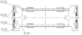
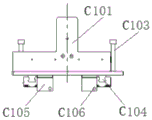
Referring to fig. 12 to 14, the main frame mechanism C1 includes a bottom frame C101, a first slider group C102, a tension spring positioning column C103, a second slider group C104, a positioning bracket C105 and a positioning bolt C106, the side of the bottom frame C101 is L-shaped, the bottom frames C101 at two ends are symmetrically arranged, and the two opposite ends of the bottom frame C101 are connected with the two ends of the slide rail of the second slider group C104 which is set by two groups of selections to form a U-shaped whole; the sliders of the second slider group C104 can move transversely on the slide rails of the second slider group C104, a group of first slider groups C102 is respectively arranged on the inner side of the vertical surface of each bottom frame C101, the sliders of the first slider groups C102 can move longitudinally on the slide rails of the second slider groups C102, and two tension spring positioning columns C103 are respectively arranged at two ends of each first slider group C102; a positioning bracket C105 is respectively arranged on the bottom surface of each underframe C101, and a positioning bolt C106 is connected on the positioning bracket C105 in a threaded manner; a lifting connection end C107 is provided at one side opposite to the upper portions of the two base frames C101.
The main frame mechanism C1 has the following functions: a bag opening/clamping mechanism C2, a center seam forming mechanism C3, a bag width adjusting mechanism C4 and a lifting mechanism C5 are fixed and connected.
Referring to fig. 15 and 16, the bag opening/clamping mechanism C2 is composed of a bag clamping main frame 201, a clamping cylinder 202, a sliding groove block 203, a bearing 204, a clamping block 205, an end positioning block 206, a main frame connecting frame 207, a retraction cylinder connecting member 208, a retraction cylinder 209, a longitudinal slider group 210, a transverse retraction cylinder 211, a transverse positioning bracket 212, a motion track bearing 213, a guide plate 214 and a tension spring 215.
The connection structure of the above components is: a clamping cylinder 202 is arranged on the side edge of the clamping main frame 201, and a sliding groove block 203 is fixed on a push rod of the clamping cylinder 202 through threads; one end of the clamping block 205 is connected with the sliding groove block 203 through a bearing, and the middle of the clamping block 205 is connected with the clamping bag main frame 201 through a shaft, so that the clamping block 205 axially rotates; the end positioning block 206 is fixed at the end of the bag clamping main frame 201; the bag clamping main frame 201 is fixed on the longitudinal sliding block group 210, and the longitudinal sliding block group 210 is fixedly arranged on the main frame connecting frame 207; the withdrawing cylinder 209 is arranged on the main frame connecting frame 207 through a withdrawing cylinder connecting piece 208 and pushes the bag clamping main frame 201 to return quickly; the transverse withdrawing cylinder 211 is fixed on the underframe C101 and pushes the bag clamping main frame 201 to return quickly; one end of the tension spring 215 is connected with the top end of the tension spring positioning column C103, and the other end is connected with one end of the bag clamping main frame 201 through a bolt T (see fig. 15). The bag opening/clamping mechanism 2 is in a symmetrical structure from left to right and front to back.
The bag opening/clamping mechanism C2 has the following functions: the clamping cylinder 202 drives the sliding groove block 203 to move transversely, so that the clamping block 205 eccentrically rotates through the bearing 204, the clamping block 205 and the end positioning block 206 are clamped, the bag is clamped, and the tension spring 215 drives the bag clamping main frame 201, the clamping cylinder 202, the sliding groove block 203, the bearing 204, the clamping block 205 and the end positioning block 206 to move transversely and longitudinally, so that transverse and longitudinal bag supporting is realized; after bagging, the push rod of the clamping cylinder 202 retracts, the clamping cylinder 202 drives the clamping block 205 to eccentrically rotate to realize the loosening with the end positioning block 206, and the bag clamping main frame 201, the clamping cylinder 202, the sliding groove block 203, the bearing 204, the clamping block 205 and the end positioning block 206 transversely and longitudinally return quickly.
Referring to fig. 17 and 18, the center seam forming mechanism C3 comprises a center seam forming cylinder 301 and a forming plate 302, wherein the center seam forming cylinder 301 is mounted on the base frame C101, and the forming plate 302 is mounted on a push rod of the center seam forming cylinder 301. The function is as follows: the bag is neat and flat.
Referring to fig. 19 and 20, the bag width adjusting mechanism C4 is composed of a left mounting base 401, a right mounting base 402, a handle 403, a front and back screw rod 404, a left nut 405 and a right nut 406, the left mounting base 401 and the right mounting base 402 are respectively fixed on the base frame C101, the front and back screw rod 404 is mounted on the left mounting base 401 and the right mounting base 402 and can rotate axially, the left nut 405 and the right nut 406 are respectively mounted on the guide plate 214, the handle 403 is mounted at the end of the front and back screw rod 404, the handle 403 is rotated to drive the front and back screw rod 404 to rotate, and the guide plate 214 is driven by the left nut 405 and the right nut 406 to move inwards or outwards at the same time.
The bag width adjusting mechanism C4 has the following functions: the distance can be manually adjusted according to the width of the bag, and various production is realized.
Referring to fig. 21 and 22, the lifting mechanism C5 is composed of a lifting slider group 501 and a connecting plate 502, the lifting slider group 501 is installed on the side surface of the base frame C101, the connecting plate 502 is installed on the lifting slider group 501, and the other end of the connecting plate 502 is externally connected to the automatic handbag bagging machine. The function is to realize the integral lifting of the main frame mechanism C1, the bag opening/clamping mechanism C2, the center seam forming mechanism C3 and the bag width adjusting mechanism C4.
The bag opening and closing mechanism CH is driven by a lifting driving mechanism when in use, the lifting driving mechanism comprises a bag opening inner joint bearing C13, a bag opening outer joint bearing C14, a bag opening connecting rod C15, a bag opening bearing seat C16, a bag opening cylinder C17 and a bag opening cylinder seat C18, the bag opening cylinder seat C18 is fixed on the frame 1 through a hinge seat C19 and is hinged with the bag opening cylinder C17 through bolts, a bag opening inner joint bearing C13 is fixed at the head of a bag opening cylinder C17, a bag opening bearing seat C16 is fixed on a frame C1 through bolts, a bag opening connecting rod C15 penetrates through a bearing hole of a bag opening bearing seat C16, and can freely rotate in the bag opening connecting rod C15, one end of the bag opening connecting rod C15 is connected with a bag opening inner joint bearing C13 fixed at the head of a bag opening cylinder C17 through a bolt and is fixed together, the other end of the bag opening connecting rod C15 is fixedly connected with a connecting rod consisting of a bag opening outer joint bearing C14 and a bag opening inner joint bearing C13 through a bolt, so that the bag opening cylinder C17 can lift and lower the bag opening and closing mechanism CH as a whole.
The working principle of the bag opening and closing mechanism CH is as follows: the double-station feeding mechanism SS sends the opened hand bag to a bag opening position (below the bag opening and closing mechanism CH), the lifting driving mechanism drives the bag opening and closing mechanism CH to integrally and simultaneously descend, the clamping cylinder 202 drives the clamping blocks 205 to rotate through the sliding groove blocks 203 and the bearing bearings 204, the clamping blocks 205 and the end positioning blocks 206 at four positions simultaneously clamp the hand bag, the returning cylinder 209 and the transverse returning cylinder 211 simultaneously return, the tension springs 215 drive four corners of the bag clamping main frame 201, the clamping blocks 205 and the end positioning blocks 206 to simultaneously pull open the hand bag under the action of self tension, and the center seam forming cylinders 301 at two ends drive the forming plates 302 to forwards push (relatively push) to form a center seam of the hand bag and shape the hand bag; after the automatic bagging machine of the handbag bags the bags, the automatic bagging machine of the handbag bags clamps the filled handbag, the clamping cylinder 202 pushes backwards to drive the clamping block 205 to rotate reversely to loosen the handbag, the returning cylinder 209 pushes the bag clamping main frame 201, the clamping block 205 and the end positioning block 206 to return simultaneously, and the transverse returning cylinder 211 pushes the main frame connecting frame 207 and drives the returning cylinder 209 to push the bag clamping main frame 201, the clamping block 205 and the end positioning block 206 to return transversely simultaneously.
Referring to fig. 23, the rotary tray surface mechanism XT includes: the device comprises a supporting surface support frame 19, a supporting surface rotary cylinder 20, a supporting surface joint bearing 21, a rotary support frame 22, a rotary sleeve seat 23, a rotary shaft sleeve 24, a rotary support 25, a supporting surface cylinder 26 and a supporting surface plate 27. The bearing surface support frame 19 is fixed on the frame 1 through a bolt, the bearing surface rotary cylinder 20 is hinged with the bearing surface support frame 19 through a bolt, a bearing surface joint bearing 21 is fixed at the head of the bearing surface rotary cylinder 20, the rotary support frame 22 is fixed on the frame 1, two rotary sleeve seats 23 are fixed on the upper surface of the rotary support frame, a rotary sleeve 24 is fixed in the rotary sleeve seat 23, a rotary support 25 penetrates through a sleeve hole of the rotary sleeve 24 and can freely rotate in the rotary support 25, the middle of the rotary support 25 is fixedly connected with the bearing surface joint bearing 21 and can rotate under the action of the bearing surface rotary cylinder 20, a bearing surface cylinder 26 is fixed at the end of the rotary support 25, and a bearing panel 27 is fixed on the bearing surface cylinder 26 through a bolt.
Referring to fig. 24 and 25, the sealing mechanism RF includes: the quick-change hot-pressing device comprises a sealing mounting plate 28, a sealing support frame 29, a sealing adjusting guide rail 30, a sealing adjusting frame 31, a sealing adjusting screw rod 32, a sealing adjusting hand wheel 33, a sealing cylinder support plate 34, a sealing tension spring support plate 35, a sealing cylinder base plate 36, a sealing cylinder 37, a sealing tension spring 38, a sealing guide frame 39, a guide bearing 40, a guide support plate 41, a hot head 42, a quick-change hot-pressing head frame 43, a quick-change hot-pressing head 44, a heat insulation plate 45, a quick-change silica gel hot-pressing head seat 46 and a silica gel strip 47.
The sealing mounting plate 28 is fixed on the frame 1, the sealing support frame 29 is fixedly connected with the sealing mounting plate 28, the two sealing adjusting guide rails 30 are respectively fixed on the left side and the right side of the sealing support frame 29, the sealing adjusting frame 31 is fixed on the two sealing adjusting guide rails 30, the sealing cylinder support plate 34 is fixed on the sealing adjusting frame 31 through bolts, the sealing tension spring support plate 35 is fixed on the sealing cylinder support plate 34, the sealing cylinder seat plate 36 is fixed on the sealing adjusting frame 31, the sealing cylinder 37 is fixed on the upper surface of the sealing cylinder seat plate, the sealing guide frame 39 is fixed on the head part of the sealing cylinder 37, the guide bearings 40 are fixed on four pivot points of the sealing guide frame 39, the guide support plate 41 is hinged with the sealing cylinder seat plate 36 and is tensioned on the sealing tension spring support plate 35 through the sealing tension spring 38, the sealing cylinder 37 is pushed out to enable the guide support plates 41 to be combined inwards, the ironing head 42 is fixed on the left side guide support plate 41, a quick-change ironing head frame 43 is fixed on the right guide plate, a quick-change ironing head 44 is fixed inside the quick-change ironing head frame 43 through a set screw, and a heat insulation plate 45 is respectively fixed on the ironing head 42 and the quick-change ironing head frame 43, so that a quick-change silica gel ironing head seat 46 and a silica gel strip 47 can be replaced to adapt to different packaging bag material requirements.
Referring to fig. 26, the bag storing and taking mechanism CQ includes: a bag storage supporting seat 77, a bag storage baffle 78, a bag storage guide rail 79, a bag storage sleeve seat 80, a bag storage screw rod 81, a bag storage handle 82, a bag storage right support 83, a bag storage left support 84, a bag storage right baffle 85, a bag storage left baffle 86, a bag storage lower baffle 87, a bag storage rotating frame 88, a bag storage sucker 89, a bag storage cylinder seat 90, a bag storage three-axis cylinder 91, a cylinder support 92, a bag storage rotating cylinder 93 and a bag storage joint bearing 94.
A bag storage supporting seat 77 is fixed on a square tube of a frame 1 through bolts, a bag storage baffle plate 78 is fixed on the bag storage supporting seat 77 through bolts, a bag storage guide rail 79 and a bag storage sleeve seat 80 are also fixed on the bag storage supporting seat 77 through bolts, two ends of the bag storage guide rail 81 are penetrated in a shaft hole of the bag storage sleeve seat 80 and can freely rotate in the hole, a bag storage handle 82 is locked at the head part of the bag storage screw rod 81, a bag storage right support 83 and a bag storage left support 84 are respectively fixed on sliding blocks at the left side and the right side of the bag storage guide rail 79 and are in threaded fit connection with the bag storage screw rod 81, the bag storage right support 83 and the bag storage left support 84 can simultaneously move inwards or outwards by rotating the bag storage screw rod 81, a bag storage right baffle plate 85 is fixed on the bag storage right support 83 through bolt connection, a bag storage left baffle plate 86 is fixed on the bag storage right support 84 through bolt connection, a bag lower baffle plate 87 is fixed on the frame 1 through bolt connection, the bag storage three-axis cylinder 91 is fixed on the bag storage cylinder seat 90, the cylinder support 92 is fixedly arranged at the head of the bag storage three-axis cylinder, the bag storage rotary cylinder 93 is hinged with the bag storage cylinder support 92, and the bag storage joint bearing 94 is fixed at the head of the bag storage rotary cylinder 93 and is hinged with the bag storage rotary frame 88.
Referring to fig. 27, the bag gripping and feeding mechanism ZS includes: the bag-feeding mechanism comprises a bag-feeding cylinder seat 95, a bag-feeding cylinder 96, a bag-clamping support frame 97, a bag-feeding support frame 98, a bag-feeding guide rail 99, a bag-clamping fixing plate 100, a bag-clamping rotating cylinder 101, a bag-clamping joint bearing 102, a bag-clamping blocking sleeve 103, a bag-clamping support shaft 104, a bag-clamping cylinder 105, a left bag-clamping gripper 106, a right bag-clamping gripper 107 and a bag-clamping base plate 108.
The bag feeding cylinder seat 95 is fixed on the frame 1 through bolts, the bag feeding cylinder 96 is hinged with the bag feeding cylinder seat 95, the bag clamping joint bearing 102 is fixed on the bag feeding cylinder 96, the bag feeding support frame 98 is fixed on the frame 1 through bolts, the bag feeding guide rail 99 is installed and fixed on the bag feeding support frame 98, one side of the bag clamping support frame 97 is fixed on a slide block of the bag feeding guide rail 99, the other side of the bag clamping joint bearing 102 is fixedly connected with the bag clamping joint bearing 102, two bag clamping fixing plates 100 are respectively fixed on two sides of the bag clamping support frame 97, the bag feeding cylinder seat 95, the bag feeding cylinder 96, the bag clamping support frame 97, the bag feeding support frame 98, the bag feeding guide rail 99, the bag clamping fixing plates 100, the bag clamping rotating cylinder 101, the bag clamping joint bearing 102, the bag clamping blocking sleeve 103, the bag clamping support shaft 104, the bag clamping cylinder 105, the left bag clamping hand 106, the right bag clamping hand 107 and the bag clamping base plate 108.
Referring to fig. 28, the bag storing and blocking mechanism CD includes: the bag storage device comprises a bag storage support frame 109, a support frame connecting plate 110, a bag blocking support frame 111, a bag blocking guide rail 112, a bag blocking sleeve seat 113, a bag blocking screw rod 114, a bag blocking right support 115, a bag blocking left support 116, a bag blocking fulcrum shaft 117, a bag blocking cylinder 118, a bag blocking knuckle bearing 119, a bag blocking right baffle 120, a bag blocking left baffle 121, a bag blocking lower guide rail 122, a bag blocking lower baffle 123, a bag blocking lower screw rod 124, a bag blocking handle 125, a bag blocking lower screw rod seat 126, a bag blocking shaft sleeve 127, a bag blocking rear baffle 128, a bag blocking front baffle 129, a bag blocking photoelectric support 130 and a bag blocking photoelectric 131.
A bag storage support frame 109 is fixed on a machine frame 1, one side of a support plate connecting plate 110 is fixedly connected with the bag storage support frame 109 through bolts, the other side is fixed on the machine frame 1, a bag blocking support frame 111 is fixed on the bag storage support frame 109 through bolts, a bag blocking guide rail 112 and a bag blocking sleeve seat 113 are both fixed on the bag blocking support frame 111 through bolts, a bag blocking screw rod 114 penetrates through shaft holes of the bag blocking sleeve seats 113 on the left side and the right side and can freely rotate in the holes, a bag blocking handle 125 is fixed at the end part of the bag blocking screw rod 114, a bag blocking right support 115 and a bag blocking left support 116 are respectively fixed on the left side and the right side of the bag blocking guide rail 112, the other end is connected with the bag blocking screw rod 114 through thread matching, the bag blocking screw rod 114 is rotated to enable the bag blocking right support 115 and the bag blocking left support 116 to simultaneously draw together inwards or separate outwards, the bag blocking 117 is fixed on the bag blocking right support 115, a bag blocking cylinder 118 is hinged with the bag blocking fulcrum shaft 117, and a bag blocking knuckle bearing 119 is fixed at the head part, a bag blocking right baffle plate 120 is hinged with the bag blocking right support 115 and fixed together with the bag blocking knuckle bearing 119, and the fixing methods of a bag blocking left baffle plate 121 and a bag blocking right baffle plate 120 are the same. The bag blocking lower guide rail 122 is fixed on the bag blocking support frame 111, the bag blocking lower baffle plate 123 is fixed on a sliding block of the bag blocking lower guide rail 122, the bag blocking lower screw rod seat 126 is fixed on the bag storage support frame 109 through bolts, the bag blocking shaft sleeve 127 is fixed in a hole of the bag blocking lower screw rod seat 126, the bag blocking lower screw rod 124 penetrates through the bag blocking shaft sleeve 127 and is in threaded fit connection with the bag blocking lower baffle plate 123, a bag blocking handle 125 is fixed at the end of the bag blocking lower screw rod 124, the bag blocking lower baffle plate 123 can ascend and descend by rotating the bag blocking lower screw rod 124, a bag blocking rear baffle plate 128 and a bag blocking front baffle plate 129 are both fixed on the bag blocking support frame 111 through bolts, the bag blocking photoelectric support 130 is fixed on the bag blocking lower baffle plate 123, and the bag blocking photoelectric support 131 is fixed on the bag blocking photoelectric support 130.
Referring to fig. 29, the double-station feeding mechanism SS includes: a feeding servo motor 132, a feeding motor seat 133, a feeding main driving belt pulley 134, a feeding synchronous belt 135, a feeding secondary driving belt pulley 136, a feeding driving bearing seat 137, a feeding driving shaft 138, a feeding main synchronous belt pulley 139, a feeding synchronous belt 140, a feeding driven shaft 141, a feeding tensioning block 142, a feeding secondary synchronous belt pulley 143, a feeding seat plate 144, a feeding guide rail 145, a feeding rear support frame 146, a feeding synchronous belt pressing plate 147, a feeding bag opening cylinder seat 148, a feeding bag opening cylinder 149, a feeding bag opening right suction cup seat 150, a feeding bag opening suction cup 151, a feeding lifting cylinder 152, a feeding bag clamping cylinder seat 153, a feeding lifting bearing 154, a feeding bearing surface cylinder 155, a feeding support panel 156, a feeding bag clamping cylinder 157, a feeding bag clamping seat plate 158, a feeding bag clamping plate 159, a feeding bag clamping tension spring 160, a feeding bag clamping pressing plate 161, a feeding bag conveying shaft seat 162, a feeding bag conveying bearing 163, A feeding front support frame 164 and a feeding bag opening left suction cup frame 165.
The feeding motor seat 133 is fixed on the frame 1 through bolts, the feeding servo motor 132 is fixed on the feeding motor seat 133, a feeding main driving belt wheel 134 is fixed on a motor shaft of the feeding servo motor through keys and set screws, two feeding driving shaft bearing seats 137 are respectively fixed on U-shaped plates 166 on two sides of the upper surface of the frame 1, the feeding driving shaft 138 penetrates through and is locked with bearing inner rings of the two feeding driving shaft bearing seats 137, but can freely rotate under the action of bearings, the feeding driven belt wheel 136 is fixed at one end of the feeding driving shaft 138 and is connected with the feeding main driving belt wheel 134 through a feeding driving synchronous belt 135 to form synchronous belt transmission, the two feeding main synchronous belt wheels 139 are fixed on the feeding driving shaft 138 through keys and set screws and are positioned at the inner sides of the U-shaped plates 166 on the front and the back sides of the frame 1, similarly, the feeding driven shaft 141 is fixed in the middle of the U-shaped plates 166 on the front and the back sides of the upper surface of the frame 1, the tension can be adjusted by a feeding tension block 142 fixed on a U-shaped plate 166 in the frame 1, two feeding secondary synchronous pulleys 143 are fixed on a feeding driven shaft 141 through bearings and elastic check rings and can freely roll, and the feeding primary synchronous pulley 139 and the feeding secondary synchronous pulley 143 are connected through a feeding conveying synchronous belt 140 to form synchronous belt transmission. The feeding base plate 144 is fixed on the U-shaped plate 166 at the front and back sides of the frame 1, the feeding guide rail 145 is fixed on the feeding base plate 144 through bolts, the feeding back support frame 146 is fixed on the guide rail slide block on the feeding guide rail 145, the feeding conveying synchronous belt 140 is contacted below the feeding back support frame, the feeding conveying synchronous belt 140 is pressed on the feeding back support frame 146 through the feeding synchronous belt press plate 147, the feeding conveying synchronous belt 140 can drive the feeding back support frame 146 to move left and right along the feeding guide rail 145, the feeding bag opening cylinder base 148 is fixed on the feeding back support frame 146, the feeding bag opening cylinder 149 is fixed on the feeding bag opening cylinder base 148, the end of the feeding bag opening cylinder 149 is fixed with the feeding bag opening right suction cup holder 150, two feeding bag opening suction cups 151 are fixed on the feeding bag opening right suction cup holder 150, the feeding lifting cylinder 152 is fixed on the feeding back support frame 146, and the end of the feeding bag clamping cylinder holder 153 is fixed on the end, two feeding lifting bearings 154 are fixed on two sides of the lower surface of a feeding bag clamping cylinder frame 153, a feeding surface supporting cylinder 155 is fixed under the feeding bag clamping cylinder frame 153 through bolts, a feeding surface supporting plate 156 is fixed on a cylinder rod at the end part of the feeding surface supporting cylinder 155, a feeding bag clamping cylinder 157 is fixed above the feeding bag clamping cylinder frame 153 through bolts, a feeding bag clamping seat plate 158 is fixed on the feeding bag clamping cylinder 157, the left side and the right side of the feeding bag clamping seat plate 158 are respectively connected with two feeding bag clamping plates 159, the two feeding bag clamping plates 159 and the feeding bag seat plate 158 are in floating connection formed through bearings, the two feeding bag clamping plates 159 are tensioned together through a feeding bag tension spring 160, feeding bag clamping pressure plates 161 are fixed on the two feeding bag clamping plates 159, a feeding bag conveying bearing 163 is fixed on a feeding bag conveying bearing seat 162 through bolts, the bag feeding and conveying bearing block 162 is fixed on the bag feeding and clamping cylinder frame 153 through bolts, and the fixing mode of the feeding front support frame 164 and the feeding bag opening left suction disc frame 165 is the same as that of the feeding rear support frame 146 and the feeding bag opening right suction disc frame 150.
The working process of the whole machine of the invention is as follows: a bag grabbing and feeding mechanism (ZS) takes down the hand bag taken out by the bag storage and taking mechanism (CQ) and temporarily stores the hand bag in a bag storage and blocking mechanism CD, a double-station feeding mechanism SS sends the hand bag to a bag opening and closing mechanism CH, and the bag opening and closing mechanism (CH) opens the hand bag below a blanking mechanism L (waiting for blanking); meanwhile, the hoister C conveys and puts the materials into the blanking mechanism L, and the materials are dropped and loaded into the handbag; the rotary surface supporting mechanism XT finishes the function of arranging materials, the double-station feeding mechanism SS sends the hand bags filled with the materials to the hot sealing mechanism RF, and the hot sealing mechanism RF finishes sealing and falls onto the belt A.
Firstly, the hoister C finishes feeding, materials are put into a double-layer hopper blanking part 5 in the blanking mechanism L to be blanked, and the lead screw guide rail adjusting part 6 can be adjusted to adapt to different material lengths and bag opening widths. The size of the bag can be adjusted by rotating the bag storage screw 81, the bag storage three-shaft cylinder 91 and the bag storage rotary cylinder 93 are simultaneously pushed forwards to enable the bag storage sucker 89 to be pressed on the packaging bag, meanwhile, the vacuum pump works to suck the packaging bag, the bag storage rotary cylinder 93 retracts to pull out one end of the packaging bag, the bag sending cylinder 96 retracts to drive the bag clamping support frame 97 to ascend, the bag clamping rotary cylinder 101 retracts to enable the bag clamping fixing plate 100 to incline upwards for a certain angle, the bag clamping cylinder 105 retracts to enable the left bag clamping gripper 106 and the right bag clamping gripper 107 to be combined to clamp one end of the packaging bag, the bag storage three-shaft cylinder retracts to move back to the yielding position, the bag clamping rotary cylinder 101 pushes out to enable the bag clamping fixing plate 100 to rotate back to the original position, then the bag sending cylinder 96 pushes out to drive the bag clamping support frame 97 to descend to a certain position, the bag clamping cylinder 105 pushes out to enable the left bag clamping gripper 106 and the right bag clamping gripper 107 to loosen, the packaging bags are positioned among a bag blocking rear baffle 128, a bag blocking front baffle 129 and a bag blocking lower baffle 123, the height of the bag blocking lower baffle 123 can be adjusted through a bag blocking lower screw rod 124 to adapt to different bag lengths, a bag blocking right baffle 120 and a bag blocking left baffle 121 rotate towards the middle under the action of a bag blocking cylinder 118 to block the left side and the right side of the bags, after a bag blocking photoelectric sensor 131 detects a right packaging bag, a feeding servo motor 132 moves, a feeding conveying synchronous belt 140 drives a feeding rear support frame 146 to integrally translate towards the right, after the right packaging bag reaches a proper position, a feeding bag opening cylinder 149 is pushed out, a feeding bag opening sucker 151 clamps the packaging bags, meanwhile, a vacuum pump starts to work to enable the feeding bag opening sucker 151 to suck the packaging bags, the bag blocking right baffle 120 and the bag blocking left baffle 121 return to the original positions under the action of the bag blocking cylinder 118, the feeding rear support frame 146 integrally translates towards the left to the corresponding positions, the feeding bag opening cylinder 149 returns, the feeding bag opening sucker 151 pulls the packaging bags apart by a certain distance, the bag opening and closing mechanism (CH) moves downwards integrally under the action of the bag opening cylinder 17, the bag opening/clamping mechanism 9 is inserted into the bag opening of the packaging bag which is pulled open to complete the bag opening and clamping actions, the bag width adjusting mechanism 11 can be adjusted to adapt to different bag opening sizes, the bag opening cylinder 17 drives the bag opening and closing mechanism (CH) to move upwards integrally, the double-layer hopper blanking part 5 in the double-layer blanking mechanism (SJ) starts blanking, meanwhile, the surface pressing and bag entering part 6 presses the materials into the packaging bag synchronously, the feeding servo motor 132 acts, the feeding conveying synchronous belt 140 drives the feeding rear supporting frame 146 to move leftwards integrally and move to the position shown in figure 10, the feeding lifting cylinder 152 pushes out to push the feeding bag clamping cylinder frame 153 to ascend, and the feeding supporting panel 156 clamps the packaged materials and the packaging bags under the action of the surface supporting cylinder 155, the center seam forming mechanism 10 folds the bag into an M shape, the feeding bag clamping cylinder 157 pushes out to enable the feeding bag clamping plate 159 to clamp the opening of the packaging bag, the surface supporting rotary cylinder 20 pushes the rotary support 25 to rotate to a corresponding position, the supporting plate 28 is continuously pushed out and returned under the action of the surface supporting cylinder 27 to complete the surface supporting action, the feeding servo motor 132 acts to enable the feeding conveying synchronous belt 140 to drive the feeding rear support frame 146 to integrally translate rightwards to the lower side of a heat sealing opening mechanism (RF), the sealing cylinder 37 acts to enable the ironing head 42 and the quick-change ironing head 44 to be tightly pressed on the packaging bag to complete the sealing action, the sealing of different packaging film materials can be adapted by replacing the quick-change silica gel ironing base 46 and the silica gel strip 47, after the sealing is completed, the feeding bag clamping cylinder 157 and the feeding surface supporting cylinder 155 return, and the sealed packaging bag falls onto the output belt A to complete the output.
Claims (12)
1. A blanking type portable bag packaging machine is characterized by comprising a blanking mechanism (L), a bag storage and taking mechanism (CQ), a bag grabbing and feeding mechanism (ZS), a bag storage and blocking mechanism (CD), a bag opening and closing mechanism (CH), a double-station feeding mechanism (SS), a rotary plane supporting mechanism (XT) and a hot sealing mechanism (RF) which are fixed on a rack structure (J), wherein the blanking mechanism (L) is integrally installed at the middle upper part of the rack structure (J); the bag opening and closing mechanism (CH) is arranged right below the blanking mechanism (L); a double-station feeding mechanism (SS) is arranged below the bag opening and closing mechanism (CH); the bag storage and taking mechanism (CQ) is arranged on the left side of the blanking mechanism (L); the bag grabbing and feeding mechanism (ZS) and the bag storing and blocking mechanism (CD) are both arranged below the bag storing and taking mechanism (CQ), and the bag storing and blocking mechanism (CD) is positioned in front of the bag grabbing and feeding mechanism (ZS); the rotary supporting surface mechanism (XT) is arranged below the double-station feeding mechanism (SS); the hot-stamping sealing mechanism (RF) is arranged on the right side of the blanking mechanism (L).
2. The blanking type portable bag packaging machine according to claim 1, wherein the blanking mechanism (L) is a double-layer blanking mechanism, the double-layer blanking mechanism comprises a frame body (1), a double-layer hopper blanking part (SL), a screw guide rail adjusting part (ST) and a synchronous dough pressing and bag feeding part (YJ), and the double-layer hopper blanking part (SL) is arranged at a position near the front of the middle part of the frame body (1); the screw guide rail adjusting parts (ST) are arranged on the left side and the right side of the double-layer hopper blanking part (SL) and are respectively connected with the double-layer hopper blanking part (SL); the synchronous dough pressing and bag feeding part (YJ) is arranged on the frame body (1) and is positioned behind the double-layer hopper blanking part (SL).
3. The blanking type handbag packing machine as recited in claim 2, wherein said double hopper blanking portion (SL) comprises: upper guide rail (S), connecting plate (S), front bent plate (S), front baffle plate (S), rear bent plate (S), rear baffle plate (S), upper supporting surface cylinder (S), upper supporting panel (S), fixed shaft sleeve (S), upper blanking plate swing arm (S), upper blanking cylinder (S), upper joint bearing (S), support shaft (S), lower guide rail (S), fixed plate (S), support plate (S), cylinder seat (S), lower blanking cylinder (S), lower joint bearing (S), sleeve seat (S), front blanking plate (S), lower support seat (S), right baffle plate (S), left baffle plate (S), rear blanking plate (S), three-shaft cylinder seat (S), three-shaft cylinder (S), lower supporting panel (S), photoelectric support (S), upper photoelectric support (S), lower photoelectric support (S), upper baffle plate (S), lower baffle plate (S), upper gas cylinder seat (S), The upper surface leveling cylinder (S39), the lower cylinder seat (S45) and the lower surface leveling cylinder (S46), the upper guide rail (S2) and the lower guide rail (S15) are fixed on the frame body (S1), and the upper side of the front baffle (S5) is connected with the front bent plate (S4); the front bent plate (S4) and the connecting plate (S3) are installed on the slider of the upper guide rail (S2) together, the lower side of the front baffle plate (S5) is fixed on the supporting plate (S17), and the two ends of the supporting plate (S17) are connected on the slider of the lower guide rail (S15) through the fixing plates (S16); the left side and the right side of the rear baffle (S7) are fixed on the other slide block on the guide rail (S2) through a rear bent plate (S6), and the front baffle (S5) and the rear baffle (S7) are arranged in a front-rear opposite mode; a pop-up surface cylinder (S8) is fixed on the front baffle (S5), and a pop-up panel (S9) is fixed on a piston rod of the pop-up surface cylinder (S8); two sides of the lower part of the front baffle (S5) are respectively provided with a supporting arm (S501) which extends forwards, a fixed shaft sleeve (S10) is rotatably supported between the two supporting arms (S501), one end of an upper blanking plate swing arm (S11) is respectively connected to the two ends of the fixed shaft sleeve (S10) close to the two ends, and an upper blanking plate is connected between the other ends of the two upper blanking plate swing arms (S11); a support shaft (S14) is fixedly supported between the two upper blanking plate swing arms (S11); the bottom end of an upper blanking cylinder (S12) is hinged to the front side of the lower part of the front baffle (S5), a piston rod of the upper blanking cylinder (S12) is connected with a supporting shaft (S14) through an upper joint bearing (S13), and the supporting shaft (S14) is driven to rotate through the expansion and contraction of the piston rod of the upper blanking cylinder (S12), so that the blocking surface action of the blanking plate is realized; a cylinder seat (S18) is connected to the lower surface of the supporting plate (S17), a lower blanking cylinder (S19) is hinged to the cylinder seat (S18), and a piston rod of the lower blanking cylinder (S19) faces to the front end; the small shafts at the two ends of the upper edge of the front material plate (S22) are rotatably supported between the two sides of the front end of the bottom of the front baffle plate (S5) through sleeve seats (S21), and a piston rod of the lower blanking cylinder (S19) is hinged with a convex seat arranged in the middle of the upper edge of the front material plate (S22) through a lower knuckle bearing (S20); one end of a lower supporting seat (S23) is slidably mounted at the rear part of the lower guide rail (S15) through a sliding block, and the bottom ends of a right baffle plate (S24) and a left baffle plate (S25) are respectively fixed on the lower supporting seat (S23); a small shaft at the two ends of the upper edge of the rear material plate (S26) is rotatably supported between the far ends of the lower edges of the right baffle (S24) and the left baffle (S25) through a shaft sleeve, a convex seat is also arranged in the middle of the upper edge of the rear material plate (S26), and a piston rod of another blanking cylinder (S19) is hinged with the convex seat in the middle of the upper edge of the rear material plate (S26) through another lower joint bearing (S20); the bottom end of the falling material cylinder (S19) is hinged on the right baffle (S24); a triaxial cylinder (S28) is arranged on a lower supporting seat (S23) through a triaxial cylinder seat (S27), a lower supporting panel (S29) is arranged on a piston rod of the triaxial cylinder (S28), and the lower supporting panel (S29) is positioned between a right baffle (S24) and a left baffle (S25); an upper photoelectric device (S31) is arranged above the upper guide rail (S2), the upper photoelectric device (S31) is fixed on a photoelectric bracket (S30), and the photoelectric bracket (S30) is fixed on a hoist or other matched equipment; a lower photoelectric device (S32) is arranged behind the left baffle (S25); an upper baffle plate (S33) and a lower baffle plate (S34) are arranged at the upper right part and the lower right part of the front baffle plate (S5) and the rear baffle plate (S7), the upper baffle plate (S33) is connected to a piston rod of an upper flush cylinder (S39), the upper flush cylinder (S39) is fixed on an upper cylinder seat (S38), and the upper cylinder seat (S38) is installed on a relevant part of the screw guide rail adjusting part (ST); the lower baffle (S34) is fixed on a piston rod of a lower flush cylinder (S46), the lower flush cylinder (S46) is fixed on a lower cylinder seat (S45), and the lower cylinder seat (S45) is installed on the related part of the screw guide adjusting part (ST).
4. The blanking type handbag packing machine as recited in claim 3, wherein said lead screw guide adjusting portion (ST) comprises: the device comprises an upper adjusting guide rail (S35), an upper bearing sleeve seat (S36), an upper adjusting screw rod (S37), a five-star hand wheel (S40) and a locking block (S41); the upper adjusting guide rail (S42), the lower adjusting sleeve seat (S43), the lower adjusting screw rod (S44), the front and rear bearing sleeve seats (S47) and the front and rear adjusting screw rod (S48), the upper adjusting guide rail (S35) is fixed on the connecting plate (S3), the upper bearing seat (S36) is positioned at two ends of the upper adjusting guide rail (S3) and fixed on the connecting plate (S3), and the upper adjusting screw rod (S37) passes through the upper bearing seats (S36) at two sides in a rotating way; one side of the upper cylinder seat (S38) is fixed on the upper adjusting guide rail (S35), and the other side of the upper cylinder seat is in threaded fit connection with the upper adjusting screw rod (S37); the locking block (S41) is fixed on the upper bearing seat (S36) through a bolt, and is sleeved on the upper adjusting screw rod (S37), and the five-star hand wheel (S40) is locked on the upper adjusting screw rod (S37) through a screw;
the lower adjusting guide rail (S42) is fixed on a frame body (S1) through bolts, a lower adjusting sleeve seat (S43) is pressed on the lower adjusting guide rail (S42), a lower adjusting screw rod (S44) penetrates through holes of two lower adjusting sleeve seats (S43) and can freely rotate in the hole of the lower adjusting sleeve seat (S43), the lower cylinder seat (S45) is slidably installed in a guide groove of the lower adjusting guide rail (S35), a screw hole is formed in the lower cylinder seat (S45) and installed on the lower adjusting screw rod (S44), and a five-star hand wheel (S40) is locked on the lower adjusting screw rod (S44) through a screw;
the front and rear bearing sleeve seats (S47) are fixed on the frame body (S1), the front and rear adjusting screw rod (S48) passes through the bearing hole of the front and rear bearing seat (S47) in a rotating manner, the front and rear screws on the front and rear adjusting screw rod (S48) are respectively connected with the lower supporting seat (S23) and the supporting plate (S17) in a threaded fit manner, and the front and rear screw rod can drive the lower supporting seat (S23) and the supporting plate (S17) to move inwards or outwards simultaneously in a rotating manner; the locking block (S41) is fixed on the front and rear bearing sleeve seats (S47) and is sleeved on the head optical axis of the front and rear adjusting screw rod (S48); a five-star hand wheel (S40) is locked on the front and rear adjusting screw rod (S48) through a screw.
5. The blanking mechanism of claim 2, wherein the synchronous nip bagging section (YJ) comprises: a press surface motor (S49), a press surface motor base (S50), a transmission synchronous pulley (S51), a transmission synchronous belt (S52), a driving shaft (S53), a driving synchronous pulley (S54), a lower mounting plate (S55), a suspension bearing base (S56), a driven shaft (S57), a driven synchronous pulley (S58), a vertical bearing base (S59), an upper mounting plate (S60), a press surface guide rail (S61), a guide rail fixing plate (S62), a synchronous belt pressing plate (S63), a press surface mounting plate (S64), a press surface supporting plate (S65), a press surface connecting plate (S66), a left press surface plate (S67), a right press surface plate (S68), an upper photoelectric bracket (S69), an upper proximity switch (S70), a lower photoelectric bracket (S71), a lower proximity switch (S72) and a synchronous belt (S73), wherein the press surface motor (S49) is fixed on the press surface motor base (S50), the transmission synchronous belt pulley (S51) is fixed on a motor shaft (S49), the surface pressing motor base (S50) and the lower mounting plate (S55) are both fixed on the frame body (S1); the suspension bearing seat (S56) is fixed on the lower mounting plate (S55), and the driving shaft (S53) rotates to penetrate through a bearing inner hole of the suspension bearing seat (S56); two driving synchronous pulleys (S54) are fixed at the middle part of the driving shaft (S53) through keys and jackscrews, another transmission synchronous pulley (S51) is fixed at the end part of the driving shaft (S53), and the two transmission synchronous pulleys (S51) are connected through a transmission synchronous belt (S52); the upper mounting plate (S60) is fixed on the frame body (S1), and two vertical bearing seats (S59) are arranged at two sides of the upper mounting plate (S60); two ends of a driven shaft (S57) are rotatably arranged in bearing inner holes of two vertical bearing seats (S59), two driven synchronous pulleys (S58) are rotatably arranged on the driven shaft (S57), and a synchronous belt (S73) is connected between the driving synchronous pulley (S54) and the driven synchronous pulley (S58); a press surface guide rail (S61) is fixed on a frame body (S1), a guide rail fixing plate (S62) is fixed on a slide block of the press surface guide rail (S61), two ends of a press surface mounting plate (S64) are fixed on a guide rail fixing plate (S62), and a synchronous belt pressing plate (S63) presses the synchronous belt (S73) on the press surface mounting plate (S64); two pressure face support plates (S65) are fixed on the middle symmetrical position of the pressure face mounting plate (S64), two pressure face connecting plates (S66) connect the heads of the two pressure face support plates (S65), the left pressure face plate (S67) is fixed on the lower pressure face connecting plate (S66), the right pressure face plate (S67) is fixed on the upper pressure face connecting plate (S66); the upper photoelectric bracket (S69) and the lower photoelectric bracket (S71) are both fixed on the bracket body (S1), the upper proximity switch (S70) is fixed on the upper photoelectric bracket (S69), and the lower proximity switch (S72) is fixed on the lower photoelectric bracket (S71).
6. The blanking type portable bag packaging machine according to claim 1, wherein the bag opening and closing mechanism CH comprises: the bag opening/clamping mechanism (C2) is installed on the main frame mechanism (C1) through a sliding block group, the center seam forming mechanism (C3) is fixed at the bottom of the main frame mechanism (C1) through a cylinder, the bag width adjusting mechanism (C4) is fixed on the main frame mechanism (C1), and the lifting mechanism (C5) is fixed on the outer side of the main frame mechanism (C1).
7. The blanking type handbag packaging machine as claimed in claim 1, characterized in that said rotary tray mechanism (XT) comprises: the plane supporting device comprises a plane supporting support frame (19), a plane supporting rotary cylinder (20), a plane supporting joint bearing (21), a rotary support frame (22), a rotary sleeve seat (23), a rotary shaft sleeve (24), a rotary support (25), a plane supporting cylinder (26) and a plane supporting plate (27), wherein the plane supporting support frame (19) is fixed on a rack (1), the plane supporting rotary cylinder (20) is hinged with the plane supporting support frame (19), the plane supporting joint bearing (21) is fixed at the head of the plane supporting rotary cylinder (20), the rotary support frame (22) is fixed on the rack (1), two rotary sleeve seats (23) are fixed on the rotary support frame (22), the rotary shaft sleeve (24) is fixed in the rotary sleeve seat (23), and the rotary support frame (25) rotates to penetrate through a shaft sleeve hole of the rotary shaft sleeve (24); the middle of the rotating bracket (25) is connected with the bearing surface joint bearing (21) and can rotate under the action of the bearing surface rotating cylinder (20); a supporting surface cylinder (26) is fixed at the end part of the rotating bracket (25), and a supporting surface plate (27) is fixed on the supporting surface cylinder (26).
8. The blanking type handbag packaging machine as claimed in claim 1, characterized in that said heat sealing mechanism (RF) comprises: a sealing mounting plate (28), a sealing support frame (29), sealing adjusting guide rails (30), a sealing adjusting frame (31), a sealing adjusting screw rod (32), a sealing adjusting hand wheel (33), a sealing cylinder support plate (34), a sealing tension spring support plate (35), a sealing cylinder seat plate (36), a sealing cylinder (37), a sealing tension spring (38), a sealing guide frame (39), a guide bearing (40), a guide support plate (41), a ironing head (42), a quick-change ironing head frame (43), a quick-change ironing head (44), a heat insulation plate (45), a quick-change silica gel ironing head seat (46) and a silica gel strip (47), wherein the sealing mounting plate (28) is fixed on the frame (1), the sealing support frame (29) is fixedly connected with the sealing mounting plate (28), the two sealing adjusting guide rails (30) are respectively fixed on the left side and the right side of the sealing support frame (29), the sealing adjusting frame (31) is fixed on the two sealing adjusting guide rails (30), a sealing cylinder support plate (34) is fixed on a sealing adjusting frame (31), a sealing tension spring support plate (35) is fixed on the sealing cylinder support plate (34), a sealing cylinder seat plate (36) is fixed on the sealing adjusting frame (31), a sealing cylinder (37) is fixed on the opening cylinder seat plate (36), a sealing guide frame (39) is fixed at the head of the sealing cylinder (37), and guide bearings (40) are fixed on four supporting points of the sealing guide frame (39); the guide support plate (41) is hinged with the sealing cylinder seat plate (36) and is tensioned on the sealing tension spring support plate (35) through a sealing tension spring (38), and a piston rod of the sealing cylinder (37) extends out to enable the guide support plate (41) to be combined inwards; an ironing head (42) is fixed on the left side guide support plate (41), a quick-change ironing head frame (43) is fixed on the right side of the left side guide support plate (41), the quick-change ironing head (44) is fixed inside the quick-change ironing head frame (43) through a set screw, and a heat insulation plate (45) is respectively fixed on the ironing head (42) and the quick-change ironing head frame (43); the silica gel strip (47) is installed inside the quick-change silica gel hot-pressing head seat (46) and is connected through interference fit, and the whole of the quick-change silica gel hot-pressing head seat (46) and the silica gel strip (47) can adapt to different packaging bag material requirements.
9. The blank type handbag packing machine as claimed in claim 1, wherein said bag storage and taking mechanism (CQ) comprises: a storage bag supporting seat (77), a storage bag baffle (78), a storage bag guide rail (79), a storage bag sleeve seat (80), a storage bag screw rod (81), a storage bag handle (82), a storage bag right support (83), a storage bag left support (84), a storage bag right baffle (85), a storage bag left baffle (86), a storage bag lower baffle (87), a storage bag rotating frame (88), a storage bag sucker (89), a storage bag cylinder seat (90), a storage bag triaxial cylinder (91), a cylinder bracket (92), a storage bag rotating cylinder (93) and a storage bag joint bearing (94), wherein the storage bag supporting seat (77) is fixed on the frame (1), the storage bag baffle (78) is fixed on the storage bag supporting seat (77), and the storage bag guide rail (79) and the storage bag sleeve seat (80) are both fixed on the storage bag supporting seat (77); two ends of the bag storage screw rod (81) penetrate through the shaft holes of the bag storage sleeve seat (80) and can freely rotate in the holes; a bag storage handle (82) is locked at the head of the bag storage screw rod (81), and a bag storage right support (83) and a bag storage left support (84) are respectively fixed on the sliding blocks at the left side and the right side of the bag storage guide rail (79) and are in threaded fit connection with the bag storage screw rod (81); the storage bag right support (83) and the storage bag left support (84) can move inwards or outwards simultaneously by rotating the storage bag screw rod (81); a storage bag right baffle (85) is fixed on a storage bag right support (83), a storage bag left baffle (86) is fixed on the storage bag right support (84), and a storage bag lower baffle (87) is fixed on the frame (1); the bag storage three-axis cylinder (91) is fixed on the bag storage cylinder seat (90), and the head of a piston rod of the bag storage three-axis cylinder (91) is provided with a cylinder support (92); the bag storage rotary cylinder (93) is hinged with the bag storage cylinder support (92); the bag storage joint bearing (94) is arranged at the top end of a piston rod of the bag storage rotary cylinder (93), and the bag storage joint bearing (94) is hinged with the bag storage rotary frame (88).
10. The blanking type handbag packing machine as claimed in claim 1, characterized in that said bag-grasping and feeding mechanism (ZS) comprises: the bag-feeding mechanism comprises a bag-feeding cylinder seat (95), a bag-feeding cylinder (96), a bag-clamping support frame (97), a bag-feeding support frame (98), a bag-feeding guide rail (99), a bag-clamping fixing plate (100), a bag-clamping rotating cylinder (101), a bag-clamping joint bearing (102), a bag-clamping blocking sleeve (103), a bag-clamping support shaft (104), a bag-clamping cylinder (105), a left bag-clamping gripper (106), a right bag-clamping gripper (107) and a bag-clamping base plate (108), wherein the bag-feeding cylinder seat (95) is fixed on a rack (1), and the bag-feeding cylinder (96) is hinged with the bag-feeding cylinder seat (95); the bag clamping joint bearing (102) is fixed on the bag feeding cylinder (96), the bag feeding support frame (98) is fixed on the frame (1), and the bag feeding guide rail (99) is fixedly arranged on the bag feeding support frame (98); one side of the bag clamping support frame (97) is fixed on the slide block of the bag feeding guide rail (99), and the other side is fixedly connected with the bag clamping joint bearing (102); the two bag clamping fixing plates (100) are respectively fixed on two sides of the bag clamping support frame (97); a bag clamping supporting shaft (104) is fixed between the two bag clamping fixing plates (100) through bolts and can rotate together; the cylinder body of the bag clamping rotating cylinder (101) is hinged with the bag clamping support frame (97) through a bolt, the piston rod of the bag clamping rotating cylinder (101) is fixedly provided with another bag clamping joint bearing (102), the bag clamping joint bearing (102) is sleeved on the bag clamping support shaft (104), the bag clamping joint bearing is pushed out by the bag clamping rotating cylinder (101) to return, and the two bag clamping fixing plates (100) can rotate upwards for an angle around the fixed point on the bag clamping support frame (97); the left bag clamping hand (106) and the right bag clamping hand (107) are fixed on the bag clamping fixing plate (100) through bearings and bolts in bearing holes of the left bag clamping hand and the right bag clamping hand, and teeth on the left bag clamping hand (106) and the right bag clamping hand (107) are meshed with each other and can be opened or closed in a rotating mode around a fixed point; the cylinder body of the bag clamping cylinder (105) is hinged with the bag clamping fixing plate (100), a bag clamping joint bearing (102) is fixed on the piston rod of the bag clamping cylinder, the bag clamping joint bearing (102) is hinged with the left bag clamping hand (106), and the bag clamping base plate (108) is respectively fixed on the left bag clamping hand (106) and the right bag clamping hand (107).
11. The blanking type handbag packing machine as claimed in claim 1, characterized in that said bag storage and retaining mechanism (CD) comprises: the bag storage support frame (109), a support frame connecting plate (110), a bag blocking support frame (111), a bag blocking guide rail (112), a bag blocking sleeve seat (113), a bag blocking screw rod (114), a bag blocking right support (115), a bag blocking left support (116), a bag blocking fulcrum shaft (117), a bag blocking cylinder (118), a bag blocking knuckle bearing (119), a bag blocking right baffle (120), a bag blocking left baffle (121), a bag blocking lower guide rail (122), a bag blocking lower baffle (123), a bag blocking lower screw rod (124), a bag blocking handle (125), a bag blocking lower screw rod seat (126), a bag blocking shaft sleeve (127), a bag blocking rear baffle (128), a bag blocking front baffle (129), a bag blocking photoelectric support (130) and a bag blocking photoelectric support (131), wherein the bag storage support frame (109) is fixed on the rack (1); one side of the supporting plate connecting plate (110) is fixedly connected with the bag storage supporting frame (109), and the other side is fixed on the rack (1); the bag blocking support frame (111) is fixed on the bag storage support frame (109), and the bag blocking guide rail (112) and the bag blocking sleeve seat (113) are fixed on the bag blocking support frame (111); the bag blocking screw rods (114) penetrate through shaft holes of the bag blocking sleeve seats (113) on the left side and the right side and can freely rotate in the shaft holes; a bag blocking handle (125) is fixed at the end part of the bag blocking screw rod (114), one end of a bag blocking right support (115) and one end of a bag blocking left support (116) are respectively fixed at the left side and the right side of the bag blocking guide rail (112) through countersunk holes on the bag blocking right support (115) and the bag blocking left support (116), screw holes on the bag blocking right support (115) and the bag blocking left support (116) are connected with the bag blocking screw rod (114) through threaded matching, and the bag blocking right support (115) and the bag blocking left support (116) can be simultaneously drawn together or separated outwards by rotating the bag blocking screw rod (114); a bag blocking fulcrum shaft (117) is fixed on a bag blocking right support (115), a bag blocking cylinder (118) is hinged with the bag blocking fulcrum shaft (117), and a bag blocking joint bearing (119) is fixed at the head of the bag blocking cylinder; the bag blocking right baffle (120) is hinged with the bag blocking right support (115) and fixed with the bag blocking joint bearing (119); the left bag blocking baffle (121) and the right bag blocking baffle (120) are arranged in a left-right symmetrical mode in the same installation mode; the lower bag blocking guide rail (122) is fixed on the lower bag blocking support frame (111), the lower bag blocking baffle (123) is fixed on a sliding block of the lower bag blocking guide rail (122), the lower bag blocking screw rod seat (126) is fixed on the bag storage support frame (109), and the bag blocking shaft sleeve (127) is fixed in a hole of the lower bag blocking screw rod seat (126); the bag blocking lower screw rod (124) penetrates through the bag blocking shaft sleeve (127) and is in threaded fit connection with the bag blocking lower baffle plate (123); a bag blocking handle (125) is fixed at the end part of the bag blocking lower screw rod (124), and the bag blocking lower baffle (123) can ascend and descend by rotating the bag blocking lower screw rod (124); the bag blocking rear baffle (128) and the bag blocking front baffle (129) are fixed on the bag blocking support frame (111); the bag blocking photoelectric support (130) is fixed on the bag blocking lower baffle (123), and the bag blocking photoelectric support (131) is fixed on the bag blocking photoelectric support (130).
12. The blanking type handbag packaging machine as claimed in claim 1, characterized in that said double station feeding mechanism (SS) comprises: a feeding servo motor (132), a feeding motor seat (133), a feeding main driving belt wheel (134), a feeding transmission synchronous belt (135), a feeding slave driving belt wheel (136), a feeding transmission bearing seat (137), a feeding driving shaft (138), a feeding main synchronous belt wheel (139), a feeding transmission synchronous belt (140), a feeding driven shaft (141), a feeding tensioning block (142), a feeding slave synchronous belt wheel (143), a feeding seat plate (144), a feeding guide rail (145), a feeding rear support frame (146), a feeding synchronous belt pressing plate (147), a feeding bag opening cylinder seat (148), a feeding bag opening cylinder (149), a feeding bag opening right suction disc frame (150), a feeding bag opening suction disc (151), a feeding lifting cylinder (152), a feeding bag clamping cylinder frame (153), a feeding lifting bearing (154), a feeding bearing surface cylinder (155), a feeding bearing plate (156), a feeding bag clamping cylinder (157), The feeding bag clamping mechanism comprises a feeding bag clamping seat plate (158), a feeding bag clamping plate (159), a feeding bag clamping tension spring (160), a feeding bag clamping pressure plate (161), a bag feeding conveying bearing seat (162), a bag feeding conveying bearing (163), a feeding front support frame (164) and a feeding bag opening left suction disc frame (165), wherein a feeding motor seat (133) is fixed on a rack (1), a feeding servo motor (132) is fixed on the feeding motor seat (133), and a feeding main driving belt wheel (134) is fixed on an output shaft of the feeding servo motor (132); two feeding transmission bearing seats (137) are respectively fixed on U-shaped plates (166) on two sides of the upper surface of the frame (1); the feeding driving shaft (138) penetrates through and is locked with the bearing inner rings of the two feeding transmission bearing seats (137); the feeding driven transmission belt wheel (136) is fixed at one end of the feeding driving shaft (138) and is connected with the feeding main transmission belt wheel (134) through a feeding transmission synchronous belt (135) to form synchronous belt transmission; two feeding main synchronous belt wheels (139) are fixed on the feeding driving shaft (138) and are positioned on the inner sides of the U-shaped plates (166) on the front side and the rear side of the rack (1); the feeding driven shaft (141) is fixed in the middle of the U-shaped plates (166) on the front side and the rear side of the upper surface of the rack (1), and the tension is adjusted through a feeding tension block (142) fixed on the U-shaped plates (166) in the rack (1); the two feeding secondary synchronous pulleys (143) are fixed on a feeding driven shaft (141) through bearings and elastic check rings; the feeding main synchronous pulley (139) and the feeding auxiliary synchronous pulley (143) are connected through a feeding conveying synchronous belt (140) to form synchronous belt transmission; a feeding base plate (144) is fixed on U-shaped plates (166) on the front side and the rear side of a frame (1), a feeding guide rail (145) is fixed on the feeding base plate (144) through bolts, a feeding rear support frame (146) is fixed on a guide rail slide block on the feeding guide rail (145), a feeding conveying synchronous belt (140) is contacted below the feeding rear support frame (146), the feeding conveying synchronous belt (140) is tightly pressed on the feeding rear support frame (146) through a feeding synchronous belt press plate (147), so that the feeding conveying synchronous belt (140) can drive the feeding rear support frame (146) to move left and right along the feeding guide rail (145), a feeding bag opening cylinder seat (148) is fixed on the feeding rear support frame (146), a feeding bag opening cylinder (149) is fixed on the feeding bag opening cylinder seat (148), a feeding bag opening right suction disc frame (150) is fixed at the end of the feeding bag opening cylinder (149), two feeding bag opening suction discs (151) are installed and fixed on the feeding bag opening right suction disc frame (150), the feeding lifting cylinder (152) is fixed on the feeding rear support frame (146); a feeding bag clamping cylinder frame (153) is fixed at the end part of the feeding bag clamping cylinder frame, and two feeding lifting bearings (154) are arranged at two sides below the feeding bag clamping cylinder frame (153); a feeding plane supporting cylinder (155) is fixed right below a feeding bag clamping cylinder frame (153), a feeding plane supporting plate (156) is fixed on a cylinder rod at the end part of the feeding plane supporting cylinder (155), a feeding bag clamping cylinder (157) is fixed right above the feeding bag clamping cylinder frame (153), and a feeding bag clamping seat plate (158) is fixed on the feeding bag clamping cylinder (157); the left side and the right side of the feeding bag clamping seat plate (158) are respectively connected with two feeding bag clamping plates (159), the two feeding bag clamping plates (159) are in floating connection with the feeding bag clamping seat plate (158) through bearings, and the two feeding bag clamping plates (159) are tightened together through a feeding bag clamping tension spring (160); a feeding bag clamping pressure plate (161) is fixedly arranged on the two feeding bag clamping plates (159), a bag feeding conveying bearing (163) is fixed on a bag feeding conveying bearing seat (162), and the bag feeding conveying bearing seat (162) is fixed on a feeding bag clamping cylinder frame (153); the connection mode of the feeding front support frame (164) and the feeding bag opening left suction disc frame (165) is the same as the connection mode of the feeding rear support frame (146) and the feeding bag opening right suction disc frame (150).
Priority Applications (1)
| Application Number | Priority Date | Filing Date | Title |
|---|---|---|---|
| CN202011364082.XA CN113493032A (en) | 2020-11-27 | 2020-11-27 | Blanking type handbag packaging machine |
Applications Claiming Priority (1)
| Application Number | Priority Date | Filing Date | Title |
|---|---|---|---|
| CN202011364082.XA CN113493032A (en) | 2020-11-27 | 2020-11-27 | Blanking type handbag packaging machine |
Publications (1)
| Publication Number | Publication Date |
|---|---|
| CN113493032A true CN113493032A (en) | 2021-10-12 |
Family
ID=77995075
Family Applications (1)
| Application Number | Title | Priority Date | Filing Date |
|---|---|---|---|
| CN202011364082.XA Pending CN113493032A (en) | 2020-11-27 | 2020-11-27 | Blanking type handbag packaging machine |
Country Status (1)
| Country | Link |
|---|---|
| CN (1) | CN113493032A (en) |
Cited By (2)
| Publication number | Priority date | Publication date | Assignee | Title |
|---|---|---|---|---|
| CN114589965A (en) * | 2022-03-08 | 2022-06-07 | 温州民望机械设备有限公司 | Woven bag opening folding machine and opening folding method |
| CN114889865A (en) * | 2022-06-11 | 2022-08-12 | 佛山市森富智能包装设备有限公司 | Vertical strip-shaped bag secondary packaging machine |
-
2020
- 2020-11-27 CN CN202011364082.XA patent/CN113493032A/en active Pending
Cited By (4)
| Publication number | Priority date | Publication date | Assignee | Title |
|---|---|---|---|---|
| CN114589965A (en) * | 2022-03-08 | 2022-06-07 | 温州民望机械设备有限公司 | Woven bag opening folding machine and opening folding method |
| CN114589965B (en) * | 2022-03-08 | 2023-11-28 | 温州民望机械设备有限公司 | Woven bag mouth folding machine and mouth folding method |
| CN114889865A (en) * | 2022-06-11 | 2022-08-12 | 佛山市森富智能包装设备有限公司 | Vertical strip-shaped bag secondary packaging machine |
| CN114889865B (en) * | 2022-06-11 | 2023-06-27 | 佛山市森富智能包装设备有限公司 | Vertical strip-shaped bag secondary packaging machine |
Similar Documents
| Publication | Publication Date | Title |
|---|---|---|
| CN113493032A (en) | Blanking type handbag packaging machine | |
| CN108382650B (en) | Grabbing type bagging machine | |
| CN102887241A (en) | Automatic costume packaging machine | |
| CN109168987B (en) | Edible fungus lantern ring framing machine | |
| CN114313488A (en) | Width adjusting mechanism, bagging assembly with same and packaging machine | |
| CN214085128U (en) | Blanking type handbag packaging machine | |
| CN113800049A (en) | Rotating disc type packaging machine | |
| CN212048095U (en) | Bag feeding mechanism for packaging bag | |
| CN211845134U (en) | Bag opening and unfolding mechanism for large packaging bag | |
| CN211663549U (en) | Food vacuum packaging flattening device | |
| CN210973026U (en) | Degradable plastic woven bag stacking device | |
| CN111361787A (en) | Chain bag-feeding type filling and packaging machine | |
| CN116176944A (en) | Bag packing device | |
| CN213414467U (en) | Taper labeller | |
| CN112977963A (en) | Rotating disc type mechanical clamping device | |
| CN216547037U (en) | Rotating disc type mechanical clamping device | |
| CN221563588U (en) | Packaging machine for wet towel production | |
| CN113104306B (en) | M bag packaging machine | |
| CN218199092U (en) | Carton unpacking and sealing all-in-one machine | |
| CN218113168U (en) | Opening and clamping mechanism | |
| CN212099547U (en) | General type bagging machine that M shape sack propped open completely and recovered | |
| CN218084473U (en) | Sealing device and automatic sealing equipment for nozzle packaging bags | |
| CN214084948U (en) | Blanking mechanism | |
| CN219506949U (en) | Support frame of multilayer plane belt feeder | |
| CN221914830U (en) | Paste box-packed case all-in-one |
Legal Events
| Date | Code | Title | Description |
|---|---|---|---|
| PB01 | Publication | ||
| PB01 | Publication | ||
| SE01 | Entry into force of request for substantive examination | ||
| SE01 | Entry into force of request for substantive examination |