CN113473006B - Information processing apparatus, image pickup apparatus, information processing system, information processing method, and non-transitory computer-readable medium - Google Patents
Information processing apparatus, image pickup apparatus, information processing system, information processing method, and non-transitory computer-readable medium Download PDFInfo
- Publication number
- CN113473006B CN113473006B CN202110688471.6A CN202110688471A CN113473006B CN 113473006 B CN113473006 B CN 113473006B CN 202110688471 A CN202110688471 A CN 202110688471A CN 113473006 B CN113473006 B CN 113473006B
- Authority
- CN
- China
- Prior art keywords
- communication
- image
- mode
- remote controller
- unit
- Prior art date
- Legal status (The legal status is an assumption and is not a legal conclusion. Google has not performed a legal analysis and makes no representation as to the accuracy of the status listed.)
- Active
Links
Images


Classifications
-
- H—ELECTRICITY
- H04—ELECTRIC COMMUNICATION TECHNIQUE
- H04N—PICTORIAL COMMUNICATION, e.g. TELEVISION
- H04N23/00—Cameras or camera modules comprising electronic image sensors; Control thereof
- H04N23/60—Control of cameras or camera modules
- H04N23/63—Control of cameras or camera modules by using electronic viewfinders
-
- H—ELECTRICITY
- H04—ELECTRIC COMMUNICATION TECHNIQUE
- H04N—PICTORIAL COMMUNICATION, e.g. TELEVISION
- H04N23/00—Cameras or camera modules comprising electronic image sensors; Control thereof
- H04N23/60—Control of cameras or camera modules
- H04N23/65—Control of camera operation in relation to power supply
- H04N23/651—Control of camera operation in relation to power supply for reducing power consumption by affecting camera operations, e.g. sleep mode, hibernation mode or power off of selective parts of the camera
-
- H—ELECTRICITY
- H04—ELECTRIC COMMUNICATION TECHNIQUE
- H04N—PICTORIAL COMMUNICATION, e.g. TELEVISION
- H04N23/00—Cameras or camera modules comprising electronic image sensors; Control thereof
- H04N23/60—Control of cameras or camera modules
- H04N23/66—Remote control of cameras or camera parts, e.g. by remote control devices
- H04N23/661—Transmitting camera control signals through networks, e.g. control via the Internet
-
- H—ELECTRICITY
- H04—ELECTRIC COMMUNICATION TECHNIQUE
- H04N—PICTORIAL COMMUNICATION, e.g. TELEVISION
- H04N23/00—Cameras or camera modules comprising electronic image sensors; Control thereof
- H04N23/60—Control of cameras or camera modules
- H04N23/667—Camera operation mode switching, e.g. between still and video, sport and normal or high- and low-resolution modes
-
- H—ELECTRICITY
- H04—ELECTRIC COMMUNICATION TECHNIQUE
- H04N—PICTORIAL COMMUNICATION, e.g. TELEVISION
- H04N5/00—Details of television systems
- H04N5/76—Television signal recording
- H04N5/765—Interface circuits between an apparatus for recording and another apparatus
- H04N5/77—Interface circuits between an apparatus for recording and another apparatus between a recording apparatus and a television camera
- H04N5/772—Interface circuits between an apparatus for recording and another apparatus between a recording apparatus and a television camera the recording apparatus and the television camera being placed in the same enclosure
Abstract
The present application relates to an information processing apparatus, an image pickup apparatus, an information processing system, an information processing method, and a non-transitory computer readable medium. An information processing apparatus includes: an information processing apparatus comprising: a communication unit configured to communicate with the image pickup apparatus via a communication path selected from a plurality of different communication paths including a first communication path and a second communication path; an operation unit; a control unit configured to switch between a first communication state of communicating with the image pickup apparatus via a first communication path and a second communication state of communicating with the image pickup apparatus via at least a second communication path during capturing of an image by the image pickup apparatus in accordance with an operation of the operation unit; and a display unit configured to display recording process execution/stop state information for the image pickup apparatus in the first communication state and the second communication state.
Description
The present application is a divisional application of the invention patent application having chinese patent application No. 201680073832.3, PCT application No. PCT/JP2016/084542 with application date 2016, 11/22/2016, entitled "information processing apparatus, image pickup apparatus, information processing system, information processing method, and non-transitory computer readable medium".
Cross Reference to Related Applications
This application claims the benefit of japanese priority patent application JP2015-249608, filed on 12/2015, 22, which is incorporated herein by reference in its entirety.
Technical Field
The present disclosure relates to an information processing apparatus, an image pickup apparatus, an information processing system, an information processing method, and a program. In more detail, the present disclosure relates to an information processing apparatus, an image pickup apparatus, an information processing system, an information processing method, and a program that control pickup processing or image display processing performed by a camera with a remote control operation.
Background
In recent years, the size and weight of a digital still camera or a digital video camera have been reduced, and cameras having a communication function are increasingly used and developed.
For example, there is a system in which a display for image display is provided to a remote controller capable of intercommunicating with a camera, start or stop of pickup performed by the camera is controlled with a remote control operation, and a picked-up image may be displayed on the display of the remote controller.
Note that examples of the related art disclosing a system capable of controlling the operation of a camera using a remote controller include: patent document 1.
In a system in which a camera is controlled by a remote controller, an image picked up by the camera can be transmitted to the remote controller and displayed on a display of the remote controller, and a user as an operator of the remote controller can issue an instruction to start or stop an image recording process.
Both the camera and the remote controller are equipped with a battery, and power is supplied from the battery to perform various data processes such as an image pickup process, an image display process, and a communication process between the remote controller and the camera.
However, image transmission, image display processing, and other data communication processing consume a large amount of power. On the other hand, the battery mounted on the camera or the remote controller has a limited capacity. Therefore, it is expected to reduce power consumption as much as possible.
CITATION LIST
Patent literature
Patent document 1: japanese patent application laid-open No.2015-127920
Disclosure of Invention
Technical problem
In view of the circumstances as described above, for example, it is desirable to provide an information processing apparatus, an image pickup apparatus, an information processing system, an information processing method, and a program that achieve reduction in power consumption in a system in which a remote controller is used to control camera operations.
Solution to the problem
According to a first embodiment of the present disclosure, there is provided an information processing apparatus including: a communication unit configured to communicate with an external device via a communication path selected from different communication paths; an operation unit; and a control unit configured to change the device mode according to the state of the operation unit, and change the mode of communication performed by the communication unit in response to the change of the device mode.
In one example, an information processing apparatus includes: a communication unit configured to communicate with an external device via a communication path selected from a first communication path and a second communication path, the first communication path being different from the second communication path. The apparatus further comprises an operating unit and a control unit. The control unit is configured to change the device mode and change the mode of communication performed by the communication unit according to the state of the operation unit.
The operation state includes a state in which the operation unit is being operated and a state in which there is no input to the operation unit for a predetermined time or longer. In a state where there is no input to the operation unit for a predetermined period of time, it is considered that the operation unit is not operated by the user for a sufficient amount of time to support updating of the device mode and the mode of communication.
According to a second embodiment of the present disclosure, there is provided an image pickup apparatus including: an image pickup unit that picks up an image; a communication unit configured to communicate with a remote controller via a communication path selected from a different communication path; and a control unit configured to change a device mode according to an operation state of an operation unit of the remote controller, and change a mode of communication performed by the communication unit in response to the change of the device mode.
According to a third embodiment of the present disclosure, there is provided an information processing system including: an image pickup unit; and a remote control device controlling the image pickup device, the remote control device including a communication unit configured to communicate with the image pickup device via a communication path, the communication path being selected from different communication paths; an operation unit and a control unit configured to change a device mode according to an operation state of the operation unit and change a mode of communication performed by the communication unit in response to the change of the device mode, the image pickup device including a communication unit configured to communicate with a remote control device via a communication path selected from different communication paths; and a control unit configured to change the device mode according to an operation state of an operation unit of the remote control device, and change the mode of communication performed by the communication unit in response to the change of the device mode.
According to a fourth embodiment of the present disclosure, there is provided an information processing method performed by an information processing apparatus including a communication unit, an operation unit, and a control unit, the information processing method including: communicating with an external device via a communication path by a communication unit, the communication path being selected from different communication paths; changing, by the control unit, the device mode according to an operation state of the operation unit; and changing, by the control unit, a mode of communication performed by the communication unit in response to the change in the device mode.
According to a fifth embodiment of the present disclosure, there is provided an information processing method performed by an image pickup apparatus including an image pickup unit, a communication unit, and a control unit, the information processing method including: picking up an image by an image pickup unit; communicating with a remote control device by the communication unit via a communication path, the communication path being selected from a different communication path; changing, by the control unit, a device mode according to an operation state of an operation unit of the remote controller; and changing, by the control unit, a mode of communication performed by the communication unit in response to the change in the device mode.
According to a sixth embodiment of the present disclosure, there is provided a program for causing an information processing apparatus to execute information processing, the information processing apparatus including: a communication unit configured to communicate with an external device via a communication path selected from different communication paths; an operation unit; and a control unit configured to change the device mode according to an operation state of the operation unit, and change the mode of communication performed by the communication unit in response to the change of the device mode.
According to a seventh embodiment of the present disclosure, there is provided a program for causing an image pickup apparatus to execute information processing, the image pickup unit including: an image pickup unit configured to pick up an image; a communication unit configured to communicate with a remote controller via a communication path selected from a different communication path; and a control unit configured to change a device mode according to an operation state of an operation unit of the remote controller, and change a mode of communication performed by the communication unit in response to the change of the device mode.
Note that examples of the program according to the seventh embodiment of the present disclosure include a program that can be provided, for example, in a computer-readable form from a recording medium or a communication medium to an information processing apparatus, a computer, and a system capable of executing various programs and codes. By providing such a program in a computer-readable form, processing according to the program is realized on the information processing apparatus, the computer, and the system.
These and other objects, features and advantages of the present disclosure will become more apparent in view of the following detailed description based on the embodiments of the present disclosure or the accompanying drawings described later. Note that "system" in this specification refers to a logical set configuration of a plurality of devices, and those devices having respective configurations are not necessarily provided in the same housing.
Advantageous effects of the invention
According to the configuration of the embodiment of the present disclosure, reduction in power consumption can be achieved by changing the communication mode according to the set mode in the communication apparatus that uses a plurality of communication paths together.
Specifically, in an information processing system including an image pickup apparatus and a remote control apparatus that controls the image pickup apparatus, for example, a communication unit of the image pickup apparatus and a communication unit of the remote control apparatus are configured to communicate with each other by communication selected from Wi-Fi communication and bluetooth (BT: registered trademark) communication, and when an operation unit of the remote control apparatus is not operated for a predetermined period of time or longer, the control unit of the image pickup apparatus and the control unit of the remote control apparatus stop the Wi-Fi communication and communicate with each other only by the BT communication.
According to this configuration, reduction in power consumption can be achieved by changing the communication mode according to the set mode in the communication apparatus that uses a plurality of communication paths together.
Note that the effects described in the specification are merely examples. The effects are not limited to those described in the specification. Further, the present disclosure may have effects other than the exemplary effects.
Drawings
Fig. 1 is a diagram illustrating an example of using a camera and a remote controller.
Fig. 2 is a diagram illustrating an example of display data shown on the display unit of the remote controller.
Fig. 3 is a diagram illustrating icons as display data shown on the display unit of the remote controller.
Fig. 4 is a diagram illustrating an example of display data shown on the display unit of the remote controller.
Fig. 5 is a diagram illustrating an example of display data shown on the display unit of the remote controller.
Fig. 6 is a diagram illustrating an example of display data shown on the display unit of the video camera.
Fig. 7 is a diagram illustrating an example of communication between a camera and a remote controller.
Fig. 8 is a diagram illustrating features of Wi-Fi communication and Bluetooth (BT) communication.
Fig. 9 is a diagram illustrating an example of setting a mode of communication between the camera and the remote controller according to the mode.
Fig. 10 is a diagram illustrating state transitions and mode transitions of a remote controller.
Fig. 11 is a diagram illustrating state transition and mode transition of the video camera.
Fig. 12 is a diagram illustrating a transition sequence of display data shown on the display unit of the remote controller according to state transition and mode transition of the remote controller.
Fig. 13 is a diagram illustrating another embodiment to which the configuration of the present disclosure is applied.
Fig. 14 is a diagram illustrating an example of changing a mode of a communication support mode in another embodiment to which the configuration of the present disclosure is applied.
Fig. 15 is a diagram illustrating a configuration example of a camera and a remote controller.
Fig. 16 is a diagram illustrating a configuration example of hardware of a remote controller or a PC.
Detailed Description
Hereinafter, details of an information processing apparatus, an image pickup apparatus, an information processing system, an information processing method, and a program according to embodiments of the present disclosure will be described with reference to the drawings. Note that description will be made in the following order.
1. Configuration example with respect to information processing system including camera operable by remote controller
2. Relating to Wi-Fi communication and Bluetooth (BT) communication
3. Method for processing communication between camera and remote controller and mode conversion
4. State transition and mode transition for remote controller
5. State transition and mode transition for video camera
6. Switching sequence of display data shown on display unit of remote controller
7. With respect to another embodiment
8. Configuration of information processing apparatus
9. Summary of configurations of the disclosure
1. Configuration example with respect to information processing system including camera operable by remote controller
First, a configuration example of an information processing system including a camera that can be operated by a remote controller will be described.
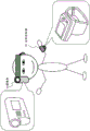
Fig. 1 is a diagram illustrating an example of using a camera that can be operated by a remote controller.
The size and weight of recent cameras or video cameras have been reduced. As shown in fig. 1, even if the user wears the camera as if the camera is fixed on the body (e.g., head) of the user, the user (photographer) can take an image without feeling that the weight of the camera is so large.
However, if the user wears the video camera 10 on his/her head as shown in fig. 1, the user may not be able to operate the operation unit of the main body of the video camera 10 and see the display image shown on the display unit of the main body of the video camera 10.
Processing such as start or stop of pickup and confirmation of a picked-up image performed by the video camera 10 can be performed using the remote controller 20 equipped with a display unit (monitor) shown in fig. 1. The user wears the remote controller 20 on his/her arm.
The video camera 10 and the remote controller 20 each include, for example, a communication unit configured to perform Wi-Fi communication, bluetooth (BT: registered trademark) communication, or the like, and are configured to be able to transmit images or various data such as operation information and status information (status) to each other.
Fig. 2 shows a configuration of the remote controller 20 and a display example of the display unit 21 of the remote controller 20.
As shown in fig. 2, the remote controller 20 includes a display unit 21 and an operation unit 22. The display unit 21 is configured to also function as a touch panel type operation unit.
On the display unit 21, display data shown in part (a) of fig. 2, for example, is displayed.
A display example of the display unit 21 shown in part (a) of fig. 2 shows a display state of an image picked up by the camera 10.
An image picked up via the image pickup unit of the camera 10 is displayed on the central display area of the display unit. Note that an image picked up via the image pickup unit of the video can be displayed on the display unit 21 even during execution or stop of the recording process.
For example, the user (photographer) can control pickup performed by the video camera 10 while viewing a display image shown on the display unit 21. Pickup includes start or stop of recording processing and still image pickup. The processing can be performed by operating the operation unit 22.
The operation information of the operation unit 22 is transmitted from the communication unit of the remote controller 20 to the communication unit of the video camera 10. The control unit of the video camera 10 performs processing according to the received operation information.
Note that it is also possible to display a User Interface (UI) including operation buttons for these operations and the like on the display unit 21 of the remote controller 20, and to input an instruction to start or stop image pickup by, for example, operating (touching) the UI.
As shown in part (a) of fig. 2, not only the picked-up image but also various information is displayed on the display unit 21. Various kinds of information are displayed, for example, on the upper and lower portions of the display area of the display unit 21.
For example, communication state information, time information, battery state information, and the like are displayed on an upper region of the display unit 21. The communication state information relates to Wi-Fi communication and bluetooth (BT: registered trademark) communication, and indicates the communication state with the video camera 10.
On the other hand, on the lower area of the display unit 21, recording process execution/stop state information, recording period information, recorded image quality information, and other recording mode information are displayed.
In the example shown in fig. 2, the recording process execution/stop state information is shown by using a recording execution/stop identification lamp. During recording, the lamp is set on (white circles) and during stopping recording, the lamp is set off (black circles).
An example of a display mode of a part of icons displayed on an upper portion of the display example of the display unit 21 shown in part (a) of fig. 2 will be described with reference to fig. 3.
Fig. 3 shows the following icons.
(1) Wi-Fi connection information
(2) Bluetooth (BT: registered trademark) connection information
(3) Camera battery remaining amount information
(4) Remote controller battery remaining amount information
These are a part of icons displayed on an upper portion of the display unit 21 of the remote controller 20 shown in fig. 2.
As shown in fig. 3, in the Wi-Fi connected state in which Wi-Fi communication is enabled between the remote controller 20 and the video camera 10, an icon is set to display (1) Wi-Fi connection information.
On the other hand, in a Wi-Fi non-connected state where Wi-Fi communication is not possible between the remote controller 20 and the video camera 10, the icon is not displayed.
Similarly to (1) Wi-Fi connection information, as shown in fig. 3, an icon displaying (2) bluetooth (BT: registered trademark) connection information is set in a BT connection state in which BT communication is possible between the remote controller 20 and the video camera 10.
On the other hand, in the BT non-connection state where the BT communication is not possible between the remote controller 20 and the video camera 10, the icon is not displayed.
(3) The camera battery remaining amount information indicates the remaining amount of the battery attached to the battery of the video camera 10. As shown in fig. 3, the display mode of the battery-like icon changes according to the remaining amount of the battery.
(4) The remote controller battery remaining amount information indicates the battery remaining amount of the battery mounted on the remote controller 20. As shown in fig. 3, the display mode of the battery-like icon changes according to the remaining amount of the battery.
The remote controller 20 acquires information required for status display, including information relating to the remote controller and information relating to the camera. The remote controller 20 acquires information related to the remote controller from the inside of the remote controller 20. The remote controller 20 acquires information about the camera based on the communication data from the camera 10. The remote controller 20 receives information about the video camera 10 through Wi-Fi communication or BT communication at any time, and performs display based on the received information.
A display example of the display unit 21 of the remote controller 20 will be described with reference to fig. 4 and 5.
Fig. 4 shows a plurality of display examples of the display unit 21 of the remote controller 20 in a case where the recording process is performed in the video camera 10.
In fig. 4, the following display examples of four states are shown.
(1a) Picked-up image display status (Wi-Fi connection status)
(1b) Picked-up image non-display state (Wi-Fi connection state)
(1c) Wi-Fi connected Standby State
(1d) Wi-Fi connection stop state
(1a) The picked-up image display state (Wi-Fi connected state) is a state in which a Wi-Fi connection is established between the video camera 10 and the remote controller 20, an image (= recording process image) picked up by the video camera 10 is transmitted to the remote controller 20 through Wi-Fi communication, and the image is displayed on a central area of the display unit 21 of the remote controller 20.
Further, in the lower portion of the display unit 21, a recording execution lamp is turned on, and recording mode information is displayed.
On the upper portion of the display unit, a Wi-Fi icon and a BT icon are displayed, indicating that the Wi-Fi connection and the BT connection between the video camera 10 and the remote controller 20 are valid, and that Wi-Fi communication and BT communication are being performed.
(1b) The picked-up image non-display state (Wi-Fi connected state) is a state in which a Wi-Fi connection is established between the video camera 10 and the remote controller 20 but transmission of an image (= recording process image) picked up by the video camera 10 to the remote controller 20 through Wi-Fi communication is stopped. The image is not displayed on the central area of the display unit 21 of the remote controller 20.
In the configuration of the embodiment of the present disclosure, in order to reduce power consumption, even if the video camera 10 is performing recording processing, transmission of an image from the video camera 10 to the remote controller 20 is stopped, and image display processing on the remote controller 20 is also stopped, under a predetermined condition (for example, in a case where the remote controller 20 is not operated by the user for a predetermined period of time or longer).
By performing such image transmission stop processing or display stop processing, it is possible to reduce the consumption of a battery mounted on the video camera 10 or the remote controller 20 and achieve power saving.
The conditions of the image transmission stop process and the display stop process will be described in detail later.
In the picked-up image non-display state, the recording execution lamp is turned on, and the recording mode information is displayed in the lower portion of the display unit 21.
On the upper portion of the display unit, a Wi-Fi icon and a BT icon are displayed, indicating that the Wi-Fi connection and the BT connection between the video camera 10 and the remote controller 20 are valid, and that Wi-Fi communication and BT communication are being performed.
The user can be assured that recording is being performed or communication is being maintained based on this information.
Note that, if the user performs an operation such as an operation of the operation unit of the remote controller 20 and a touch operation of the display unit 21 having a function as a touch panel in the "(1 b) picked-up image non-display state (Wi-Fi connected state)", the remote controller 20 interprets the operation information as an image display request and outputs an image transmission request from the remote controller 20 to the video camera 10.
In a case where the camera 10 receives a request from the remote controller 20, the camera 10 starts an image transmission process.
By this processing, a transition processing for a state transition from "(1 b) picked-up image non-display state (Wi-Fi connected state)" shown in fig. 4 to "(1 a) picked-up image display state (Wi-Fi connected state)" shown in fig. 4 is performed.
A series of conversion processes will be described in detail later.
(1c) The Wi-Fi connection standby state represents a display example of the display unit 21 in which the Wi-Fi connection is not established between the video camera 10 and the remote controller 20 but the state is being shifted to the connected state.
The Wi-Fi connection icon is not displayed.
It should be noted that the recording light is turned on and the recording process continues.
In the case where the Wi-Fi connection is established in the "(1 c) Wi-Fi connection standby state", the state transitions to the "(1 a) picked-up image display state (Wi-Fi connection state)" shown in fig. 4.
For example, "(1 c) Wi-Fi connection standby state" represents a display example in a case where the Wi-Fi connection is temporarily stopped during the recording process performed by the video camera 10.
In this case, an attempt is made to establish a Wi-Fi connection between the remote controller and the video camera while continuing the recording process performed by the video camera 10, and if the connection is restored, the state transitions to "(1 a) picked-up image display state (Wi-Fi connected state)" shown in fig. 4, thereby continuing the recording process.
(1d) The Wi-Fi connection stop state represents a display example of the display unit 21 in a state where the Wi-Fi connection is not established between the video camera 10 and the remote controller 20 and the connection attempt process is not performed.
Not displaying Wi-Fi connection icon
It should be noted that the recording light is turned on and the recording process is continued.
In the system according to the embodiment of the present disclosure, a mode (BT single communication mode) in which Wi-Fi communication is automatically stopped and only BT communication is continued between the video camera 10 and the remote controller 20 is set to the power saving mode.
In the BT single communication mode, wi-Fi communication between the video camera 10 and the remote controller 20 stops, and transmission of a picked-up image by the Wi-Fi communication also stops.
In the configuration of the embodiment of the present disclosure, in order to reduce power consumption, wi-Fi communication between the video camera 10 and the remote controller 20 is stopped, transmission of a picked-up image is stopped, and minimum information is transmitted/received by using BT communication, even if the video camera 10 is performing recording processing, under a predetermined condition (for example, in a case where the remote controller 20 is not operated by the user for a predetermined period of time or longer). This mode is referred to as BT single communication mode.
By using the BT single communication mode, it is possible to further reduce the consumption of the battery mounted on the video camera 10 or the remote controller 20, and to achieve power saving.
The mode conversion process will be described in detail later.
Note that also in the (1 d) Wi-Fi connection stop state shown in fig. 4, the recording execution lamp is turned on and the recording mode information is displayed in the lower part of the display unit 21, so the user can recognize that the recording process is continued.
It should be noted that the Wi-Fi icon at the upper part of the display unit is turned off and the BT icon is displayed.
Only BT communication is effective between the video camera 10 and the remote controller 20, indicating that Wi-Fi communication is not possible but BT communication is being performed.
The user can ensure that recording is being performed and the communication status is confirmed based on this information.
Note that if the user performs an operation such as an operation of the operation unit of the remote controller 20 and an operation of a touch operation of the display unit 21 having a function as a touch panel in the "(1 d) Wi-Fi connection stop state", the remote controller 20 interprets the operation information as an image display request, performs processing for restoring Wi-Fi connection between the remote controller 20 and the video camera 10, and outputs the request for image transmission to the video camera 10.
In a case where the video camera 10 receives a request from the remote controller 20, the video camera 10 starts image transmission processing via the reconnected Wi-Fi communication path.
By this processing, a transition processing for making a transition from (1 d) Wi-Fi connection stop state shown in fig. 4 to "(1 a) picked-up image display state (Wi-Fi connection state)" shown in fig. 4 is executed.
A series of conversion processes will be described in detail later.
Next, referring to fig. 5, a display example in a case where the video camera 10 does not perform the recording process will be described as a display example of the display unit 21 of the remote controller 20.
Fig. 5 shows a plurality of display examples of the display unit 21 of the remote controller 20 in a case where the video camera 10 does not perform the recording process.
In fig. 5, display examples of the following three states are shown.
(2a) Picked-up image display status (Wi-Fi connection status)
(2b) Wi-Fi connected Standby State
(2c) Wi-Fi connection stop state
Note that even if the recording process is not performed by the video camera 10, an image is captured via the image pickup unit of the video camera 10, and the image is transmitted from the video camera 10 to the remote controller 20 as long as the power of the video camera 10 is turned on.
(2a) The picked-up image display state (Wi-Fi connected state) represents a state in which a Wi-Fi connection is established between the video camera 10 and the remote controller 20, an image (= recording processing is not performed) picked up by the video camera 10 is transmitted to the remote controller 20 through the Wi-Fi connection, and the image is displayed on a central area of the display unit 21 of the remote controller 20.
In this case, however, the recording execution lamp at the lower portion of the display unit 21 is turned off, and the recording mode information is not displayed.
The user can recognize that the display image is not recorded based on the information.
On the upper portion of the display unit, a Wi-Fi icon and a BT icon are displayed, indicating that the Wi-Fi connection and the BT connection between the video camera 10 and the remote controller 20 are valid, and that Wi-Fi communication and BT communication are being performed.
(2b) The Wi-Fi connection standby state represents a display example of the display unit 21 in which the Wi-Fi connection is not established between the video camera 10 and the remote controller 20 but the state is being shifted to the connected state.
The Wi-Fi connection icon is not displayed.
The recording light is turned off and the recording process is not performed.
In the case where the Wi-Fi connection is established in the (2 b) Wi-Fi connection standby state, the state transitions to the (2 a) picked-up image display state (Wi-Fi connected state) shown in fig. 5.
(2b) The Wi-Fi connection standby state represents, for example, a display example in a case where the Wi-Fi connection is temporarily stopped while the picked-up image of the section (2 a) of fig. 5 is displayed in the video camera 10.
In this case, an attempt is made to establish a Wi-Fi connection between the remote controller and the video camera while stopping the recording process performed by the video camera 10, the state transitions to "(2 a) picked-up image display state (Wi-Fi connected state)" shown in fig. 5 if the connection is restored, and the picked-up image is displayed.
(2c) The Wi-Fi connection stop state represents a display example of the display unit 21 in a state where the Wi-Fi connection is not established between the video camera 10 and the remote controller 20 and the connection attempt process is not performed.
Not displaying Wi-Fi connection icon
The recording light is turned off and the recording process is not performed.
As described above with reference to fig. 4 and 5, the display mode of the display unit 21 of the remote controller 20 is changed to a different display mode according to the state.
The display conversion process will be described in detail later.
2. Relating to Wi-Fi communication and Bluetooth (BT) communication
Next, a Wi-Fi connection and a bluetooth (BT: registered trademark) connection performed between the video camera 10 and the remote controller 20 will be described.
As shown in fig. 7, the video camera 10 and the remote controller 20 each include a communication unit, and Wi-Fi communication and BT communication are performed by the communication units.
The Wi-Fi communication standard includes multiple standards, such as IEEE802.11a/b/g/n.
Two frequency bands, 2.4GHz and 5GHz, can be selected to perform Wi-Fi communication. Wi-Fi communication has the characteristics of having a wide frequency band, relatively high communication speed, and a relatively large (about 100 m) communication-enabling distance, and being able to reliably transmit a large amount of data.
On the other hand, only one frequency band of 2.4GHz can be used for BT communication. The BT communication is characterized by a communication speed lower than that of the Wi-Fi communication and a communication-enabled distance (about 10 meters) lower than that of the Wi-Fi communication.
However, BT communication has an advantage of lower power consumption than Wi-Fi communication.
There are also a number of standards for BT communication. Examples of the BT communication standard include a BTLE (bluetooth low energy (registered trademark)) standard that consumes less power than that of existing BT communication. In some cases, "BTLE" is referred to as "BLE.
The Bluetooth (BT) described in the specification includes not only existing BT communication but also BT communication according to the BTLE standard.
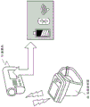
Fig. 8 is a diagram showing power consumption and transmission speed of Wi-Fi communication, BT (existing) communication, and BTLE communication.
As shown in fig. 8, wi-Fi communication has a high transmission speed, but its power consumption is high.
On the other hand, BT communication and BTLE communication have low transmission speeds, but their power consumption is low.
In the system according to the embodiment of the present disclosure, power saving can be achieved by using Wi-Fi communication and BT communication together between the video camera 10 and the remote controller 20 and controlling the Wi-Fi communication and BT communication.
3. Method for processing communication between camera and remote controller and mode conversion
Next, a communication process performed between the video camera 10 and the remote controller 20 and a mode transition according to an embodiment of the present disclosure will be described with reference to fig. 9 and subsequent drawings.
Fig. 9 is a diagram illustrating a plurality of states and modes set in the remote controller 20 and a communication mode between the remote controller 20 and the video camera 10 in each state or mode.
As shown in fig. 9, the state of the remote controller 20 shifts to three states of (X) a power-off state, (a) a recording preparation state, and (B) a recording execution state.
Further, the mode of the remote controller 20 is set to (a 1) the recording preparation image display mode in (a) the recording preparation state.
The mode of the remote controller 20 is set to any one of four modes of (B) a recording image display normal mode, (B2) a recording image non-display normal mode, (B3) a recording image non-display durable mode, and (B4) a recording image non-display Bluetooth (BT) single communication mode in a recording execution state.
The remote controller 20 performs switching between different modes according to a user's operation or under a predetermined mode switching condition.
As shown in fig. 9, a communication mode performed between the remote controller 20 and the camera 10 corresponding to each mode is defined, and the communication mode may be changed according to the mode conversion.
In a case where the mode of the remote controller 20 is set to any one of the following two modes, i.e., (a 1) a recording-ready-image display mode and (b 1) a recording-image display normal mode, images and status information are transmitted from the video camera 10 to the remote controller 20 by Wi-Fi communication, and operation information of the remote controller 20 is transmitted to the video camera 10 by using Wi-Fi communication and BT communication.
The image data transmitted from the video camera 10 by Wi-Fi communication are a picked-up image that is not recorded in (a 1) the recording-ready-image display mode, and a picked-up image (recorded image) that is recorded in (b 1) the recorded-image display normal mode.
The status information transmitted from the video camera 10 by Wi-Fi communication includes, for example, information on whether recording is performed, picked-up image quality (for example, HD and SD) information, recording time period information, and battery remaining amount information of a battery mounted to the video camera.
The operation information of the remote controller 20 is transmitted to the video camera 10 by using Wi-Fi communication and BT communication. Of the Wi-Fi communication path and the BT communication path, a communication path that transmits operation information is determined in advance according to an operation type.
For example, power ON/OFF information of the video camera 10 is transmitted via the BT communication path.
For example, operation information to start or stop the recording process is transmitted to the video camera 10 via the Wi-Fi communication path.
In addition, other operation information is transmitted to the video camera 10 via a communication path determined according to the operation type.
Note that in the case where only either one of the Wi-Fi communication path and the BT communication path is blocked, the operation information is transmitted via the other communication path being connected.
Next, a communication configuration in the case where the mode of the remote controller 20 is set to the following two modes will be described: the (b 2) recorded image non-display normal mode and (b 3) recorded image non-display durable mode shown in the central portion of fig. 9.
In the case where the mode of the remote controller 20 is set to any one of the two modes, as shown in fig. 9, the status information is transmitted from the video camera 10 to the remote controller 20 by Wi-Fi communication, and the operation information of the remote controller 20 is transmitted to the video camera 10 by using Wi-Fi communication and BT communication.
In the "(b 2) recorded image non-display normal mode" and "(b 3) recorded image non-display durable mode", an image is not transmitted from the video camera 10 to the remote controller 20.
In both modes, transmission from the camera 10 to the remote controller 20 is stopped, and image display in the remote controller 20 is also stopped.
By stopping the image transmission processing and the image display processing, the battery consumption is reduced to achieve power saving.
The status information transmitted from the video camera 10 by Wi-Fi communication includes, for example, information relating to whether recording is performed, recording image quality (e.g., HD and SD) information, recording time period information, and battery remaining amount information of a battery mounted to the video camera.
The operation information of the remote controller 20 is transmitted to the video camera 10 by using Wi-Fi communication and BT communication. Of the Wi-Fi communication path and the BT communication path, a communication path that transmits operation information is determined in advance according to an operation type.
For example, the power ON/OFF information of the video camera 10 is transmitted via the BT communication path.
For example, operation information to start or stop the recording process is transmitted to the video camera 10 via the Wi-Fi communication path.
In addition, other operation information is transmitted to the video camera 10 via a communication path determined according to the operation type.
Note that in the case where only either one of the Wi-Fi communication path and the BT communication path is blocked, the operation information is transmitted via the other communication path being connected.
Next, a communication configuration in the case where the mode of the remote controller 20 is set to the following mode will be described: (b 4) recorded image non-display Bluetooth (BT) single communication mode shown at the bottom of fig. 9.
In the case where the mode of the remote controller 20 is set to this mode, as shown in fig. 9, the status information is transmitted from the video camera 10 not by Wi-Fi communication but by BT communication, and the operation information of the remote controller 20 is transmitted to the video camera 10 only by BT communication.
That is, in the "(b 4) recorded image non-display Bluetooth (BT) single communication mode", an image is not transmitted from the video camera 10 to the remote controller 20, the Wi-Fi connection between the video camera 10 and the remote controller 20 is cut off, and data transmission via the Wi-Fi communication path is all stopped.
Communication between the video camera 10 and the remote controller 20 is performed only via the BT communication path, such as transmission of status information from the video camera 10 to the remote controller 20, and transmission of operation information from the remote controller 20 to the video camera 10.
As described above with reference to fig. 8, BT communication has lower power consumption than that of Wi-Fi communication.
Therefore, in the "(b 4) recorded image non-display Bluetooth (BT) single communication mode", power saving can be achieved by using only BT communication.
In this embodiment, the BT communication is any one of the existing BT communication and the BTLE (or BLE) communication described with reference to fig. 8.
The status information transmitted from the video camera 10 by BT communication includes, for example, information on whether recording is performed or not, recording image quality (e.g., HD and SD) information, recording time period information, and battery remaining amount information of a battery attached to the video camera.
The operation information of the remote controller 20 is transmitted only via the BT communication path.
For example, power ON/OFF information of the video camera 10, operation information to start or stop a recording process, and other operation information are all transmitted to the video camera 10 via the BT communication path.
4. State transition and mode transition in remote controller
Next, state transition and mode transition in the remote controller 20 will be described with reference to fig. 10.
As described above with reference to fig. 9, the states set in the remote controller 20 include the following three states: (X) a power off state; (A) recording a ready state; and (B) recording the execution status.
Further, the mode of the remote controller 20 is set to (a 1) the recording preparation image display mode in (a) the recording preparation state.
The mode of the remote controller 20 is set to any one of four modes of (B1) a recorded image display normal mode, (B2) a recorded image non-display normal mode, (B3) a recorded image non-display durable mode, and (B4) a recorded image non-display Bluetooth (BT) single communication mode in the recording execution state.
The remote controller 20 performs a transition between a plurality of states or modes according to a user's operation or under a predetermined transition condition.
The conversion process is performed under the control of the control unit of the remote controller 20.
The control unit of the remote controller 20 performs control to change the device mode in response to, for example, input of operation information to the operation unit of the remote controller 20 or according to a period of time in which no operation information is input thereto.
Further, the control unit performs processing to change the communication mode via the communication unit in response to the change of the device mode.
Fig. 10 is a diagram illustrating state transition and mode transition of the remote controller 20.
In fig. 10, the steps of state transition and mode transition are as shown in step S101 to step S151.
Hereinafter, the processing in each step will be described in turn.
(step S101)
Step S101 represents a state transition between (X) the power-off state and (a 1) the recording-ready image display mode in (a) the recording-ready state.
The state transition is performed by turning on/off a power switch of the remote controller 20 by a user.
In the case where the user turns on the power switch of the remote controller 20 in the (X) power off state, the mode of the remote controller 20 is changed to the (a 1) recording preparation image display mode in the (a) recording preparation state.
During the state transition process, the following processes are performed: (1) A process of establishing a Wi-Fi connection and a BT connection between the remote controller 20 and the video camera 10; (2) Starts a process of transmitting the image picked up by the camera 10 to the remote controller 20; and (3) start processing of displaying the picked-up image on the display unit 21 of the remote controller 20.
The transmission display image at this time is an image for which recording processing is not being performed.
(step S102)
Step S102 represents mode transition from (a) the recording preparation image display mode in the (a) recording preparation state to (B1) the recording image display normal mode in the (B) recording execution state.
The mode switching is performed by a recording start operation on the remote controller 20 performed by the user.
In the case where the user performs the recording start operation on the remote controller 20 in the (a 1) recording preparation image display mode in the (a) recording preparation state, the mode of the remote controller 20 shifts to the (B1) recording image display normal mode in the (B) recording execution state.
During the state transition process, the following processes are performed: (1) A process of requesting transmission of a start recording from the remote controller 20 to the video camera 10; (2) starting the process of recording performed by the camera 10; (3) A process of transmitting an image (= a recorded image) picked up by the camera 10 to the remote controller 20; and (4) a process of displaying the picked-up image (= recorded image) on the display unit 21 of the remote controller 20.
The transmission display image at this time is an image on which the recording process is being performed.
(step S103)
Step S103 represents a mode transition from the (B1) recording image display normal mode in the (B) recording execution state to the (B2) recording image non-display normal mode in the (B) recording execution state.
In the remote controller 20 in the (b 1) recorded image display normal mode, the mode transition is performed without being operated by the user for a predetermined period of time or longer (for example, 10 seconds).
The mode transition represents a mode transition in a case where the BT connection is not established between the remote controller 20 and the video camera 10.
This mode transition is performed, for example, in the case where the video camera 10 is an old model that does not have a BT communication function or the BT connection is cut off between the remote controller 20 and the video camera 10.
During this mode switching process, the following processes are performed: (1) A process of transmitting a request for stopping transmission of the recorded image from the remote controller 20 to the video camera 10; (2) Stopping the process of transmitting the image (= recorded image) picked up by the camera 10 to the remote controller 20; and (3) stop the process of displaying the picked-up image (= recorded image) on the display unit 21 of the remote controller 20.
Note that even if this mode conversion is performed, the recording process performed by the video camera 10 is continued.
Through this processing, transmission of the picked-up image from the video camera 10 to the remote controller 20 is stopped, and display of the picked-up image on the display unit 21 of the remote controller 20 is stopped.
Through this process, the battery consumption in the video camera 10 and the remote controller 20 is reduced to achieve power saving.
(step S104)
Step S104 represents a mode transition from the (B1) recorded image display normal mode in the (B) recording execution state to the (B3) recorded image non-display durable mode in the (B) recording execution state.
In the remote controller 20 in the (b 1) recorded image display normal mode, the mode transition is performed without being operated by the user for a predetermined period of time or longer (for example, 10 seconds).
The mode transition represents a mode transition in the case where a BT connection is established between the remote controller 20 and the video camera 10.
That is, the mode transition of step S103 is performed in a case where the BT connection is not established between the remote controller 20 and the video camera 10 and the mode transition of step S104 is performed in a case where the BT connection is established between the remote controller 20 and the video camera 10.
Note that in a case where the BT connection between the remote controller 20 and the video camera 10 is restored after the process of step S103 is performed, and thereafter the remote controller 20 is not operated by the user for a predetermined period of time or longer (for example, 10 seconds), the mode of the remote controller 20 is switched from the (B2) recording image non-display normal mode in the (B) recording execution state to the (B3) recording image non-display durable mode in the (B) recording execution state.
The processing performed during the mode transition processing from the (B1) recorded image display normal mode in the (B) recording execution state to the (B3) recorded image non-display durable mode in the (B) recording execution state is the same as the processing performed during the mode transition of step S103, and the following processing is performed: (1) A process of transmitting a request for stopping transmission of the recording image from the remote controller 20 to the video camera 10; (2) Stopping the process of transmitting the image (= recorded image) picked up by the camera 10 to the remote controller 20; and (3) stop the process of displaying the picked-up image (= recorded image) on the display unit 21 of the remote controller 20.
Note that even if this mode conversion is performed, the recording process performed by the video camera 10 is continued.
Through this processing, transmission of the picked-up image from the camera 10 to the remote controller 20 is stopped, and display of the picked-up image on the display unit 21 of the remote controller 20 is also stopped.
Through this process, the battery consumption in the video camera 10 and the remote controller 20 is reduced to achieve power saving.
(step S105)
Step S105 represents a mode transition from the (B3) recording image non-display durable mode in the (B) recording execution state to the (B4) recording image non-display Bluetooth (BT) single communication mode in the (B) recording execution state.
The mode transition is performed in a case where the remote controller 20 is not operated by the user for a predetermined period of time or more (for example, 60 seconds) in the (b 3) recorded image non-display durable mode.
The mode transition represents a mode transition in the case where a BT connection is established between the remote controller 20 and the video camera 10.
During this mode transition process, the following processes are performed: (1) Stopping the processing of the Wi-Fi connection between the remote controller 20 and the camera 10; (2) A process of switching from the Wi-Fi path to a BT path, which is a path that transmits the status information from the camera 10; and (3) a process of switching to only the BT communication path, which is a communication path for transmitting operation information from the remote controller 20 to the video camera 10, without using the Wi-Fi communication path.
Note that even if this mode conversion is performed, the recording process performed by the video camera 10 is continued.
Through this process, the Wi-Fi connection between the video camera 10 and the remote controller 20 is stopped.
By this process, the battery consumption in the video camera 10 and the remote controller 20 is further reduced to achieve power saving.
(step S121)
Step S121 represents mode transition from any one of (B2) the recorded image non-display normal mode in the (B) recording execution state, (B3) the recorded image non-display durable mode in the (B) recording execution state, or (B4) the recorded image non-display Bluetooth (BT) one-communication mode in the (B) recording execution state to (B1) the recorded image display normal mode in the (B) recording execution state.
This mode transition is performed in a case where the user issues an image display instruction for the remote controller 20 in any one of the (b 2) to (b 4) modes.
Note that almost all input operations performed by the user on the remote controller 20, such as a touch operation and a switching operation of the display unit having a function as a touch panel, are interpreted as image display instructions input in any one of the modes (b 2) to (b 4), and the mode conversion of step S121 is performed.
By this mode transition, the following processing is performed: (1) Resuming the processing of the Wi-Fi connection between the video camera 10 and the remote controller 20 in a case where the Wi-Fi connection is stopped; (2) A process of transmitting a picked-up image (= a recorded image) from a request of the remote controller 20 to the video camera 10; (3) A process of transmitting an image (= a recorded image) picked up by the camera 10 to the remote controller 20; and (4) a process of displaying the picked-up image (= recorded image) on the display unit 21 of the remote controller 20.
The transmission display image at this time is an image on which the recording process is being performed.
(step S122)
Step S122 represents mode transition from any one of (B1) the recording image display normal mode in the recording execution state, (B2) the recording image non-display normal mode in the recording execution state, (B3) the recording image non-display durable mode in the recording execution state, and (B4) the recording image non-display Bluetooth (BT) single communication mode in the recording execution state to (a 1) the recording preparation image display mode in the recording preparation state.
This mode transition is performed in a case where the user performs an input operation of stopping recording on the remote controller 20 in any one of the modes (b 1) to (b 4).
The input operation includes, for example, an operation of a recording stop button.
By this mode transition, the following processing is performed: (1) A process of transmitting a request to stop the recording process from the remote controller 20 to the video camera 10; (2) a process of stopping the recording process performed by the camera 10; (3) A process of transmitting an image (≠ recorded image) picked up by the camera 10 to the remote controller 20; and (4) a process of displaying the picked-up image (≠ recorded image) on the display unit 21 of the remote controller 20.
The transmission display image after the mode transition is an image for which the recording process is not being performed.
(disconnection in steps S131 to S133 and S141 and S142)
This mode transition is performed in a case where the Wi-Fi connection or the BT connection between the remote controller 20 and the video camera 10 is stopped in any one of (a) the recording preparation image display mode in the recording preparation state and (B) the recording image display normal mode in the recording execution state, (B2) the recording image non-display normal mode, (B3) the recording image non-display durable mode, and (B4) the recording image non-display Bluetooth (BT) single communication mode.
By this mode transition, as shown in fig. 10, the state of the remote controller 20 is shifted to the (Y) communication path non-connection state.
In the case where this mode transition is performed, the communication performed between the video camera 10 and the remote controller 20 is cut off.
Note that the state of the recording process performed by the video camera 10 is not changed. That is, in a case where recording is being performed, the recording process continues.
In the case where this mode transition is performed, the remote controller 20 performs a process of restoring the communication path between the remote controller 20 and the video camera 10.
That is, the remote controller 20 performs a process of restoring the Wi-Fi connection and the BT connection.
If the communication path restoration process is successful, the mode transition of "connection at step S141" or "connection at step S142" is executed.
(connection of step S141)
The mode transition of connection of step S141 represents a mode transition from the (Y) communication path non-connected state to the (b 1) recorded image display normal mode.
The mode transition is performed in a case where the mode of the remote controller 20 makes a transition from (B1) the recording image display normal mode, (B2) the recording image non-display normal mode, (B3) the recording image non-display durable mode, and (B4) the recording image non-display Bluetooth (BT) single communication mode in the (B) recording execution state to (Y) the communication path non-connection state, and then the communication path (at least Wi-Fi communication path) between the video camera 10 and the remote controller 20 is restored.
In this mode transition, the following processing is performed: (1) A process of resuming the Wi-Fi connection in a case where the Wi-Fi communication between the video camera 10 and the remote controller 20 is being stopped; (2) A process of transmitting a picked-up image (= a recorded image) from a request of the remote controller 20 to the video camera 10; (3) A process of transmitting an image (= recorded image) picked up by the camera 10 to the remote controller 20; and (4) a process of displaying the picked-up image (= recorded image) on the display unit 21 of the remote controller 20.
The transmission display image at this time is an image on which the recording process is being performed.
(connection of step S142)
The mode transition of connection at step S142 represents a mode transition from the (Y) communication path non-connected state to the (a 1) recording preparation image display mode.
The mode transition is performed in a case where the mode of the remote controller 20 makes a transition from (a 1) the recording-ready image display mode in the (a) recording-ready state to (Y) the communication-path non-connected state, and thereafter the communication path (at least Wi-Fi communication path) between the video camera 10 and the remote controller 20 is restored.
In this mode, the following processing is performed: (1) A process of resuming the Wi-Fi connection in a case where the Wi-Fi communication between the video camera 10 and the remote controller 20 is being stopped;
(2) A process of transmitting a picked-up image (≠ recorded image) request from the remote controller 20 to the video camera 10; (3) A process of transmitting an image (≠ recording image) picked up by the camera 10 to the remote controller 20; and (4) a process of displaying the picked-up image (≠ recorded image) on the display unit 21 of the remote controller 20.
The transmission display image at this time is an image for which recording processing is not being performed.
(step S151)
The mode transition of step S151 represents a state transition from the (Y) communication path unconnected state to the (X) power supply disconnected state.
This state transition is performed in a case where the user turns off the power switch of the remote controller 20 in the (Y) communication path non-connected state.
By the operation of the user, the remote controller 20 is turned off.
In the case where this state transition is performed, the following processing is performed: (1) The process of the restoration process of the communication path between the video camera 10 and the remote controller 20 is stopped.
Note that even if this state transition is performed, the processing performed by the video camera 10 continues. However, in the case where the communication path between the video camera 10 and the remote controller 20 is not restored within a predetermined period of time or longer (e.g., 1 minute) during the recording process, the recording process is automatically stopped.
5. State transition and mode transition in camera
Next, state transition and mode transition in the video camera 10 will be described with reference to fig. 11.
The state and mode of the video camera 10 are set to a plurality of states and modes corresponding to the state and mode of the remote controller 20.
The processing of setting these states or modes, the state transition processing, and the mode transition processing are executed under the control of the control unit of the video camera 10.
The control unit of the video camera 10 performs control to change the device mode in response to, for example, input of operation information to the operation unit of the remote controller 20 or according to a period of time in which no operation information is input thereto. Further, the control unit performs processing to change the communication mode via the communication unit in response to the change of the device mode.
As shown in fig. 11, the states and modes of the video camera 10 are set to the following states and modes: (X) a power off state; (P) a recording-ready image transfer mode; (Q) a recording image transfer mode; (R) a recording image non-transmission mode; and (S) a recording image non-transfer BT single communication mode.
The (P) recording-ready image transmission mode of the video camera 10 indicates a mode set when the mode of the remote controller 20 is set to the (a 1) recording-ready image display mode.
The (Q) recorded image transfer mode of the video camera 10 indicates a mode set when the mode of the remote controller 20 is set to the (b 1) recorded image display normal mode.
The (R) recorded image non-transmission mode of the video camera 10 indicates a mode set when the mode of the remote controller 20 is set to either (b 2) recorded image non-display normal mode or (b 3) recorded image non-display durable mode.
The (S) recorded image non-transmission BT single communication mode of the video camera 10 indicates a mode set when the mode of the remote controller 20 is set to the (b 4) recorded image non-display Bluetooth (BT) single communication mode.
The state and mode of the video camera 10 are switched to (X) a power-off state and (P) a recording-ready image transfer mode, (Q) a recording image transfer mode, (R) a recording image non-transfer mode, and (S) a recording image non-transfer BT single communication mode, according to the state and mode of the remote controller 20. The conversion is performed according to an operation of the user on the remote controller 20 or under a predetermined conversion condition.
Fig. 11 is a diagram illustrating state transition and mode transition.
In fig. 11, the steps of state transition and mode transition are as shown in step S201 to step S242.
Hereinafter, the processing in each step will be described in turn.
(step S201)
Step S201 represents a state transition between (X) the power-off state and (P) the recording-ready image transfer mode.
This state transition is performed by the user turning on/off the power switch of the camera in the remote controller 20.
For example, in a case where the user turns on a power switch of the video camera in the remote controller 20 in the (X) power off state, an activation signal for the video camera 10 is transmitted from the remote controller 20 to the video camera 10 via the BT communication path.
The mode of the video camera 10 is switched to (P) a recording-ready image transfer mode in response to the activation signal.
Note that the mode of the video camera 10 is set to a standby mode in which the video camera 10 can receive a signal from the remote controller even if the power supply is turned off.
During the state transition processing of step S201, the following processing is performed: (1) A process of establishing a Wi-Fi connection and a BT connection between the remote controller 20 and the video camera 10; (2) Starts a process of transmitting the image picked up by the camera 10 to the remote controller 20; and (3) start processing of displaying the picked-up image on the display unit 21 of the remote controller 20.
The transmission display image at this time is an image for which recording processing is not being performed.
(step S202)
Step S202 represents mode transition from the (P) recording preparation image transfer mode to the (Q) recording image transfer mode.
Such mode transition in the video camera 10 is performed in correspondence with the mode transition of step S102 in the remote controller 20, that is, the mode transition from the (a 1) recording preparation image display mode in the (a) recording preparation state to the (B1) recording image display normal mode in the (B) recording execution state.
The mode switching is performed in response to a recording start operation performed by the user on the remote controller 20.
In the case where the user performs the recording start operation on the remote controller 20 when the mode of the video camera 10 is the (P) recording-preparation-image transfer mode and the mode of the remote controller 20 is the (a 1) recording-preparation-image display mode in the (a) recording-preparation state, the mode of the video camera 10 is shifted to the (Q) recording-image transfer mode.
The mode of the remote controller 20 shifts to (B1) the recording image display normal mode in the (B) recording execution state.
During this state transition process, the following processes are performed: (1) A process of transmitting a request to start recording from the remote controller 20 to the video camera 10; (2) starting the process of recording performed by the camera 10; (3) A process of transmitting an image (= a recorded image) picked up by the camera 10 to the remote controller 20; and (4) a process of displaying the picked-up image (= recorded image) on the display unit 21 of the remote controller 20.
The transmission display image at this time is an image for which recording processing is being performed.
(step S203)
Step S203 represents mode transition from the (Q) recording image transfer mode to the (R) recording image non-transfer mode.
Such mode transition in the video camera 10 is performed in correspondence with the mode transition of step S103 or step S104 in the remote controller 20, i.e., the mode transition from the (B1) recording image display normal mode in the (B) recording execution state to the (B2) recording image non-display normal mode in the (B) recording execution state, or the mode transition from the (B1) recording image display normal mode in the (B) recording execution state to the (B3) recording image non-display durable mode in the (B) recording execution state.
The mode transition is performed in a case where the remote controller 20 is not performed by the user for a predetermined period of time or more (for example, 10 seconds) when the mode of the video camera 10 is the (Q) recorded image transfer mode and the mode of the remote controller 20 is the (b 1) recorded image display normal mode.
During this state transition process, the following processes are performed: (1) A process of transmitting a request for stopping transmission of the recording image from the remote controller 20 to the video camera 10; (2) Stopping the process of transmitting the image (= recorded image) picked up by the camera 10 to the remote controller 20; and (3) stop the process of displaying the picked-up image (= recorded image) on the display unit 21 of the remote controller 20.
Even if this mode conversion is performed, the recording process performed by the video camera 10 is continued.
Through this processing, transmission of the picked-up image from the camera 10 to the remote controller 20 is stopped, and display of the picked-up image on the display unit 21 of the remote controller 20 is also stopped.
Through this process, battery consumption in the video camera 10 and the remote controller 20 is reduced to achieve power saving.
(step S204)
Step S204 represents a mode transition from the (R) recording image non-transfer mode to the (S) recording image non-transfer BT single communication mode.
Such mode transition in the video camera 10 is performed in correspondence with the mode transition of step S105 in the remote controller 20, i.e., the mode transition from the (B3) recording image non-display durable mode in the (B) recording execution state to the (B4) recording image non-display Bluetooth (BT) single communication mode in the (B) recording execution state.
The mode transition is performed in a case where the remote controller 20 is not operated by the user for a predetermined period of time or more (for example, 60 seconds) when the mode of the video camera 10 is the (R) recorded image non-transmission mode and the mode of the remote controller 20 is the (b 3) recorded image non-display durable mode.
During this mode transition process, the following processes are performed: the processing is (1) processing of stopping the Wi-Fi connection between the remote controller 20 and the camera 10; (2) A process of switching from the Wi-Fi path to a BT path, which is a path for transmitting the state information from the video camera 10; (3) A process of switching to only the BT communication path, which is a communication path for transmitting operation information from the remote controller 20 to the video camera 10, without using the Wi-Fi communication path.
Note that even if this mode conversion is performed, the recording process performed by the video camera 10 is continued.
Through this process, the Wi-Fi connection between the video camera 10 and the remote controller 20 is stopped.
By this process, the battery consumption in the video camera 10 and the remote controller 20 is further reduced to achieve power saving.
(step S211)
Step S211 represents mode transition from any one of the (R) recording image non-transmission mode and the (S) recording image non-transmission BT single communication mode to the (Q) recording image transmission mode.
The mode conversion is performed in correspondence with the mode conversion of step S121 in the remote controller 20. That is, the mode transition is performed in correspondence with a mode transition from any one of (B2) the recording image non-display normal mode in the (B) recording execution state, (B3) the recording image non-display durable mode in the (B) recording execution state, and (B4) the recording image non-display Bluetooth (BT) single communication mode in the (B) recording execution state to (B1) the recording image display normal mode in the (B) recording execution state.
In the case where the above-described mode transition is performed in the remote controller 20, the video camera 10 performs mode transition from any one of (R) the recording image non-transmission mode and (S) the recording image non-transmission BT single communication mode to (Q) the recording image transmission mode.
By this mode transition, the following processing is performed: (1) Resuming the processing of the Wi-Fi connection between the camera 10 and the remote controller 20 in case the Wi-Fi connection is stopped; (2) A process of transmitting a picked-up image (= a recorded image) from a request of the remote controller 20 to the video camera 10; (3) A process of transmitting an image (= recorded image) picked up by the camera 10 to the remote controller 20; and (4) a process of displaying the picked-up image (= recorded image) on the display unit 21 of the remote controller 20.
The transmission display image at this time is an image on which the recording process is being performed.
(step S221)
Step S221 represents a mode transition from any one of the (Q) recording image transfer mode, (R) recording image non-transfer mode, and (S) recording image non-transfer BT single communication mode to the (P) recording preparation image transfer mode.
The mode conversion is performed in correspondence with the mode conversion of step S122 in the remote controller 20. That is, the video camera 10 performs mode transition from any one of (Q) the recording image transfer mode, (R) the recording image non-transfer mode, (S) the recording image non-transfer BT single communication mode to (P) the recording preparation image transfer mode, in correspondence with the mode transition from any one of (B1) the recording image display normal mode in the (B) recording execution state, (B2) the recording image non-display normal mode in the (B) recording execution state, (B3) the recording image non-display durable mode in the (B) recording execution state, and (B) the recording image non-display Bluetooth (BT) single communication mode in the (B) recording execution state to (a 1) the recording preparation image display mode in the (a) recording preparation state.
The mode switching is performed in a case where the user performs an input operation of stopping recording on the remote controller 20.
The input operation includes, for example, an operation of a recording stop button.
By this mode transition, the following processing is performed: (1) A process of transmitting a stop recording request from the remote controller 20 to the video camera 10; (2) stopping the process of recording performed by the camera 10; (3) A process of transmitting an image (≠ recorded image) picked up by the camera 10 to the remote controller 20; and (4) a process of displaying the picked-up image (≠ recorded image) on the display unit 21 of the remote controller 20.
The transmission display image after the mode transition is an image for which the recording process is not being performed.
(disconnection at steps S231, S232, S241 and S242)
The mode transition is performed in any one of (P) the recording-ready image transfer mode, (Q) the recording image transfer mode, (R) the recording image non-transfer mode, and (S) the recording image non-transfer BT single communication mode, with the Wi-Fi connection or the BT connection between the remote controller 20 and the video camera 10 stopped.
By this mode transition, the mode of the video camera 10 is shifted to the (Y) communication path non-connected state, as shown in fig. 11.
The mode transition is performed corresponding to the mode transition performed during the connection disconnection of any one of steps S131 to S133, S141, and S142 in the remote controller 20.
The mode transition is performed in a case where the Wi-Fi connection or the BT connection between the remote controller 20 and the video camera 10 is stopped in any one of (a) a recording preparation image display mode in a recording preparation state and (B) a recording image display normal mode of (a 1), (B2), (B3) and (B4) a recording image non-display Bluetooth (BT) single communication mode in a recording execution state.
In the case where this mode transition is performed, the communication between the video camera 10 and the remote controller 20 is cut off.
It should be noted that the state of the recording process performed by the video camera 10 is not changed. That is, in the case where recording is being performed, the recording process is continued.
In the case where this mode transition is performed, the remote controller 20 performs processing of restoring the communication path between the remote controller 20 and the video camera 10.
That is, the remote controller 20 performs a process of restoring the Wi-Fi connection and the BT connection.
If the communication path restoration process is successful, the mode transition of "connection at step S241" or "connection at step S242" is executed.
(connection of step S241)
The mode transition of the connection of step S241 denotes a mode transition from the (Y) communication path non-connected state to the (Q) recording image transfer mode.
This mode transition is performed in correspondence with the mode transition of step S141 in the remote controller 20, that is, the mode transition from the (Y) communication path non-connected state to the (b 1) recording image display normal mode.
The mode transition is performed in a case where the mode of the video camera 10 makes a transition from the (Q) recorded image transfer mode to the (Y) communication path non-connected state, and then the communication path (at least Wi-Fi communication path) between the video camera 10 and the remote controller 20 is restored.
In this mode transition, the following processing is performed: (1) A process of resuming the Wi-Fi connection between the video camera 10 and the remote controller 20 in a case where the Wi-Fi connection is stopped; (2) A process of transmitting a picked-up image (= a recorded image) from a request of the remote controller 20 to the video camera 10; (3) A process of transmitting an image (= a recorded image) picked up by the camera 10 to the remote controller 20; and (4) a process of displaying the picked-up image (= recorded image) on the display unit 21 of the remote controller 20.
The transmission display image at this time is an image on which the recording process is being performed.
(connection of step S242)
The mode transition of connection at step S242 represents a mode transition from the (Y) communication path non-connected state to the (P) recording preparation image transfer mode.
The mode transition is performed in correspondence with the mode transition of step S142 in the remote controller 20, that is, the mode transition from the (Y) communication path non-connected state to the (a 1) recording preparation image display mode.
The mode transition is performed in a case where the mode of the video camera 10 makes a transition from the (P) recording-ready image transfer mode to the (Y) communication-path non-connected state, and then the communication path (at least Wi-Fi communication path) between the video camera 10 and the remote controller 20 is restored.
In this mode transition, the following processing is performed: (1) Processing to resume the Wi-Fi connection between the video camera 10 and the remote controller 20 in a case where the Wi-Fi connection is stopped; (2) A process of transmitting a picked-up image (≠ recorded image) from the remote controller 20 to the request of the camera 10; (3) A process of transmitting an image (≠ recorded image) picked up by the camera 10 to the remote controller 20; and (4) a process of displaying the picked-up image (≠ recorded image) on the display unit 21 of the remote controller 20.
The transmission display image at this time is an image for which the recording process is not being performed.
6. Switching sequence of display data shown on display unit of remote controller
Next, a conversion sequence of display data shown on the display unit 21 of the remote controller 20 will be described.
Fig. 12 is a diagram illustrating a conversion sequence of display data shown on the display unit 21 of the remote controller 20.
The steps shown in fig. 12 will be described in turn.
(step S301)
The display image of step S301 is an example of a display image in the case where the mode of the remote controller 20 is set to (a) the recording preparation image display mode in (a) the recording preparation state.
On the display unit 21 of the remote controller 20, a picked-up image (≠ recorded image) transmitted from the video camera 10 is displayed, and icons indicating a Wi-Fi connection state and a BT communication state are displayed on the upper part.
The lower recording execution/stop lamp is turned off, and therefore, the user can recognize that the recording process is not executed.
(Steps S302 and S303)
Step S302 represents an operation of the remote controller 20 performed by the user. In step S302, a recording start operation is performed on the operation unit of the remote controller 20.
When this operation is performed, the following processing is performed: (1) A process of transmitting a request to start recording from the remote controller 20 to the video camera 10; (2) starting the process of recording performed by the camera 10; (3) A process of transmitting an image (= recorded image) picked up by the camera 10 to the remote controller 20; and (4) a process of displaying the picked-up image (= recorded image) on the display unit 21 of the remote controller 20.
By the operation of step S302 by the user, the mode of the remote controller 20 shifts to (B1) the recorded image display normal mode in the (B) recording execution state as shown in step S303, and the image transmitted from the video camera 10 is displayed on the display unit 21.
The transmission display image at this time is an image for which recording processing is being performed.
As shown in step S303 of fig. 12, a picked-up image (= recorded image) transmitted from the video camera 10 is displayed on the display unit 21 of the remote controller 20, and icons representing the Wi-Fi connection state and the BT communication state are displayed on the upper side.
The lower recording execution/stop lamp is turned on so that the user can recognize that the recording process is being executed.
(step S304)
Step S304 represents an operation of the remote controller 20 performed by the user. In step S304, a recording stop operation is performed on the operation unit of the remote controller 20.
When this operation is performed, the following processing is performed: (1) A process of transmitting a stop recording request from the remote controller 20 to the video camera 10; (2) stopping the process of recording performed by the camera 10; (3) A process of transmitting an image (≠ recorded image) picked up by the camera 10 to the remote controller 20; and (4) a process of displaying the picked-up image (≠ recorded image) on the display unit 21 of the remote controller 20.
By the operation of step S304 of the user, the mode of the remote controller 20 shifts to (a 1) a recording-ready-image display mode in (a) a recording-ready state as shown in step S301, and the image transmitted from the video camera 10 is displayed on the display unit 21.
The transmission display image at this time is an image for which the recording process is not being performed.
(step S305)
The control unit of the remote controller 20 measures a period of time during which the remote controller 20 is not operated by the user during the recording process, i.e., in the (B1) recorded image display normal mode in the (B) recording execution state of step S303.
In a case where the remote controller 20 is not operated for a predetermined period of time or longer (for example, 10 seconds), the determination result of step S305 is YES (YES), and the process proceeds to step S306.
Otherwise, the mode of step S303 is continued, i.e., (B1) recorded image display normal mode in the (B) recording execution state.
(step S306)
In a case where the remote controller 20 is not operated by the user for a predetermined period of time or longer (for example, 10 seconds) in step S305, the determination result of step S305 is YES, and the process proceeds to step S306.
That is, the mode of the remote controller 20 is switched to (B2) the recorded image non-display normal mode in (B) the recording execution state or (B3) the recorded image non-display durable mode in (B) the recording execution state.
In the case where the BT communication between the remote controller 20 and the video camera 10 is established, the mode of the remote controller 20 shifts to (b 3) the recorded image non-display durable mode. In the case where the BT communication between the remote controller 20 and the video camera 10 is not established, the mode of the remote controller 20 shifts to (b 2) the recorded image non-display normal mode.
In any mode, the display data shown on the display unit 21 of the remote controller 20 is similar data.
During this mode transition process, the following processes are performed: (1) A process of transmitting a request to stop transmitting a recorded image from the remote controller 20 to the video camera 10; (2) Stopping the process of transmitting the image (= recorded image) picked up by the camera 10 to the remote controller 20;
(3) The process of displaying the picked-up image (= recorded image) on the display unit 21 of the remote controller 20 is stopped.
Even if this mode conversion is performed, the recording process performed by the video camera 10 is continued.
As shown in step S306 of fig. 12, the display data shown on the display unit 21 of the remote controller 20 in the mode of step S306, that is, (B2) the recorded image non-display normal mode in the (B) recording execution state and (B3) the recorded image non-display durable mode in the (B) recording execution state, does not include an image (= recorded image) picked up by the video camera 10.
It should be noted that the communication state information on the upper part of the display unit or the recording execution/stop information on the lower part indicates that recording is being performed, and the recording mode information is also continuously displayed.
The user can recognize that the recording process is being performed based on this information.
By stopping the transmission and display of the image, the battery consumption in the remote controller 20 and the video camera 10 is reduced to achieve power saving, as shown in step S306.
(step S307)
The control unit of the remote controller 20 measures a period of time during the recording process in which the remote controller 20 is not operated by the user, i.e., (B2) the recording image non-display normal mode or (B3) the recording image non-display durable mode in the (B) recording execution state in step S306.
In a case where the remote controller 20 is not operated by the user for a predetermined period of time or longer (for example, 60 seconds) in step S307, the determination result of step S307 is YES, and the process proceeds to step S308.
Otherwise, the mode of step S307 is continued, i.e., (B2) the recorded image non-display normal mode or (B3) the recorded image non-display durable mode in the (B) recording execution state.
(step S308)
In a case where the remote controller 20 is not operated by the user for a predetermined period of time or longer (for example, 60 seconds) in step S307, the determination result of step S307 is YES, and the process proceeds to step S308.
That is, the mode of the remote controller 20 is changed to (B4) the recorded image non-display Bluetooth (BT) single communication mode in the (B) recording execution state.
During this mode transition process, the following processes are performed: (1) Stopping the processing of the Wi-Fi connection between the remote controller 20 and the camera 10; (2) A process of switching from the Wi-Fi path to a BT path, which is a path for transmitting the state information from the video camera 10; (3) A process of switching to only the BT communication path, which is a communication path for transmitting operation information from the remote controller 20 to the video camera 10, without using the Wi-Fi communication path.
Note that even if this mode conversion is performed, the recording process performed by the video camera 10 is continued.
As shown in step S308 of fig. 12, the display data shown on the display unit 21 of the remote controller 20 in the mode of step S308, i.e., the (B4) recorded image non-display Bluetooth (BT) single communication mode in the (B) recording execution state, does not include an image (= recorded image) picked up by the video camera 10.
It should be noted that the communication state information on the upper part of the display unit or the recording execution/stop information on the lower part indicates that recording is being performed, and the recording mode information is also continuously displayed.
In this mode, wi-Fi communication between the remote controller 20 and the camera 10 is stopped. Thus, the Wi-Fi icon indicating that Wi-Fi communication is active is disconnected.
The user can recognize that the recording process is being performed and the Wi-Fi communication is stopped based on the information.
By stopping the transmission and display of the image and stopping the Wi-Fi communication between the remote controller 20 and the video camera 10, the battery consumption in the remote controller 20 and the video camera 10 is further reduced to achieve power saving, as shown in step S308.
(step S309)
The process of step S309 represents that the user operates the remote controller 20 to request the image to be displayed in the state of S306 or S308 in which the recorded image is not displayed.
As described above, in the case where the recording process is being performed and the recorded image is not displayed, almost all input operations performed by the user on the remote controller 20 (such as a touch operation and a switching operation of the display unit having a function as a touch panel) are interpreted as the image display instruction input, and the process of step S309 is performed.
During the process of step S309, the following processes are executed: (1) Resuming the processing of the Wi-Fi connection between the video camera 10 and the remote controller 20 in a case where the Wi-Fi connection is stopped; (2) A process of transmitting a picked-up image (= a recorded image) from a request of the remote controller 20 to the video camera 10; (3) A process of transmitting an image (= a recorded image) picked up by the camera 10 to the remote controller 20; and (4) a process of displaying the picked-up image (= recorded image) on the display unit 21 of the remote controller 20.
As a result of the processing, the processing returns to step S303 and the recording image is displayed again.
The transmission display image at this time is an image on which the recording process is being performed.
7. With respect to another embodiment
In the above embodiment, the camera 10 and the remote controller 20 have been used. However, the configuration of mode conversion to change the communication mode according to the embodiment of the present disclosure is applicable to other various communication apparatuses.
A configuration example of a process in which mode conversion according to an embodiment of the present disclosure can be applied to change a communication mode will be described with reference to fig. 13.
Fig. 13 shows a camera built-in capsule 50 and a PC 70. The camera-embedded capsule 50 is obtained by incorporating a camera in the capsule. The capsule can be administered to a human. The camera is capable of picking up an image. The PC 70 communicates with the camera built-in capsule 50.
The PC 70 and the camera built-in capsule 50 together perform various communication processes using Wi-Fi communication and BT communication.
Specifically, the following processing is performed: (a) A process of transmitting an image picked up by the camera of the camera built-in capsule 50 to the PC 70 through Wi-Fi communication; (b) A process of transmitting information on an image picked up by the camera of the camera built-in capsule 50 or status information such as position information to the PC 70 by Wi-Fi communication or BT communication; and (c) a process of transmitting a command (for starting or stopping image pickup, zooming, or flash pickup) from the PC 70 to the camera of the camera built-in capsule 50 through Wi-Fi communication or BT communication.
Between the camera of the camera built-in capsule 50 and the PC 70, various data communications are performed.
In such data communication, power saving and battery consumption reduction can be achieved by changing the communication mode according to the above-described mode switching between the video camera 10 and the remote controller 20.
A specific example of mode conversion will be described with reference to fig. 14.
Fig. 14 shows a communication data mode supporting three modes between the camera of the camera built-in capsule 50 and the PC 70.
The three modes are: the image transfer execution mode (1), the image transfer stop mode (2), and the image transfer stop & BT single communication mode (3).
The data communication mode between the camera of the camera built-in capsule 50 and the PC 70 among the above three modes is set as follows.
(1) Image transfer execution mode
In the image transfer execution mode, the following data communication is performed: (1a) Transmitting an image picked up by the camera of the camera built-in capsule 50 to the PC 70 through Wi-Fi communication; (1b) Transmitting information about an image picked up by the camera of the camera built-in capsule 50 and status information such as position information to the PC 70 through Wi-Fi communication or BT communication; and (1 c) a command (for starting or stopping image pickup, zooming, or flash pickup) is transmitted from the PC 70 to the camera of the camera built-in capsule 50 through Wi-Fi communication or BT communication.
In this mode, an image picked up by the camera of the camera built-in capsule 50 is transmitted to the PC 70 through Wi-Fi communication, and the transmitted image is displayed on the display unit of the PC 70.
(2) Image transfer stop mode
In the image transfer stop mode, the following data communication is performed: (2a) Transmitting information about an image picked up by the camera of the camera built-in capsule 50 and status information such as position information to the PC 70 through Wi-Fi communication or BT communication; and (2 b) a command (for starting or stopping image pickup, zooming, or flash pickup) is transmitted from the PC 70 to the camera of the camera built-in capsule 50 through Wi-Fi communication or BT communication.
In this mode, a process of transmitting an image picked up by the camera of the camera built-in capsule 50 to the PC 70 by Wi-Fi communication is not performed, and a process of displaying the picked-up image on the PC 70 is also stopped.
By stopping the image transmission/display processing, the battery consumption in the battery of the camera built-in capsule 50 or the battery consumption in the battery of the PC 70 is reduced to achieve power saving.
(3) Image transfer stop & BT single communication mode
In the image transfer stop & BT single communication mode, the following data communication is performed: (3a) Transmitting information on an image picked up by the camera of the camera built-in capsule 50 and status information such as position information to the PC 70 only by BT communication; and (3 b) sending a command (for starting or stopping image pickup, zooming, or flash pickup) from the PC 70 to the camera of the camera built-in capsule 50 only by BT communication.
In this mode, a process of transmitting an image picked up by the camera of the camera built-in capsule 50 to the PC 70 by Wi-Fi communication is not performed, and a process of displaying the picked-up image on the PC 70 is also stopped.
In addition, wi-Fi communication for other data is also stopped.
By stopping the image transmission/display processing and stopping the Wi-Fi communication, the battery consumption in the battery of the camera built-in capsule 50 or the battery consumption in the battery of the PC 70 is further reduced to achieve power saving.
In addition to the configurations described above with reference to fig. 13 and 14, by performing the process of changing the communication mode according to the mode transition of the embodiment of the present disclosure in various communication systems using Wi-Fi communication and BT communication, the battery consumption in each device can be reduced to achieve power saving.
8. Arrangement relating to information processing apparatus
Next, a hardware configuration example of each information processing apparatus constituting the information processing system according to the embodiment of the present disclosure will be described with reference to fig. 15 and subsequent drawings.
Fig. 15 is a block diagram showing a configuration example of the video camera 10 and the remote controller 20 shown in fig. 1.
The video camera 10 includes a control unit 101, an image pickup unit 102, a display unit 103, an input unit (operation unit) 104, an output unit 105, a storage unit 106, a communication unit 107, and a time measurement unit 108.
The control unit 101 controls data processing performed in the video camera 10, such as image pickup control, display control, data transmission/reception control, and mode change control. For example, the control unit 101 includes a CPU having a function of executing a program, and executes processing according to an application (program) stored in the storage unit 106.
Specifically, for example, the control unit 101 executes the processing according to the above-described sequence.
The image pickup unit 102 is an image pickup unit for image pickup, and picks up a moving image or a still image. During the pickup processing, the pickup start timing or the pickup stop timing is controlled under the control of the control unit 101.
For example, as described above with reference to fig. 6, the display unit 103 is used to display information on the communication state with the remote controller 20, the battery remaining amount information, and the like. Further, processing of displaying a picked-up image, reading the picked-up image from the storage unit 106 to display the image, and the like can also be performed using the display unit 103.
For example, the input unit 104 may be operated by a user, and various operation instructions are issued for the input unit 104. The touch panel type display unit is also a part of the input unit.
The output unit 105 includes an image output unit, a sound output unit, and a data output unit for an external apparatus. The display unit 103 is also a component of the output unit 105.
For example, the storage unit 106 includes a RAM, a ROM, or other recording media. The storage unit 106 is used as a storage area for picked-up images and as a storage area for application programs executed by the control unit 101. Further, for example, the storage unit 106 is used as a work area or a storage area for parameters applied to data processing performed by the control unit 101.
The communication unit 107 is used to perform processing for communication with an external device such as the remote controller 20, and is used for data communication via various communication paths such as wireless communication including Wi-Fi communication and BT communication and wired communication using, for example, a communication cable.
In the example shown in fig. 15, a communication path with the communication unit 206 of the remote controller 20 is shown.
As in the above-described embodiment, various communications are performed by the communication units of the two devices.
For example, operation information of the remote controller 20 and the like are transmitted to the video camera 10, and the video camera 10 controls, for example, start or stop of recording. Further, a command for starting or stopping transmission of a picked-up image is transmitted from the remote controller 20 to the video camera 10, and the picked-up image is transmitted from the video camera 10 to the remote controller 20.
The time measurement unit 108 has, for example, a clock function representing information on the current time and a timer function for measuring a time period since the start of pickup. Further, the time measurement unit 108 is used to measure a period of time during which no operation information is input from the remote controller.
The remote controller 20 includes a control unit 201, a display unit 202, an input unit (operation unit) 203, an output unit 204, a storage unit 205, a communication unit 206, and a time measurement unit 207.
The control unit 201 controls data processing performed in the remote controller 20, such as image display control, data transmission/reception control, operation information analysis, and mode change control. For example, the control unit 201 includes a CPU having a function of executing a program, and executes processing according to an application (program) stored in the storage unit 205.
Specifically, for example, the control unit 201 executes the processing according to the above-described sequence.
For example, as described above with reference to fig. 4, the display unit 202 is used to display an image picked up by the camera 10, information on the communication state with the camera 10, remaining battery amount information, and the like.
For example, the input unit 203 may be operated by a user, and various operation instructions are issued for the input unit 203. The touch panel type display unit is also a part of the input unit.
The output unit 204 includes an image output unit, a sound output unit, and a data output unit for the external apparatus. The display unit 202 is also a component of the output unit 204.
For example, the storage unit 205 includes a RAM, a ROM, or other recording media. The storage unit 205 is used as a storage area of the picked-up image and as a storage area of an application program executed by the control unit 201. Further, for example, the storage unit 205 is used as a work area or a storage area for parameters applied to data processing performed by the control unit 201.
The communication unit 206 is used to perform processing for communication with an external device such as the video camera 10, and is used for data communication via various communication paths such as wireless communication including Wi-Fi communication and BT communication and wired communication using, for example, a communication cable.
In the example shown in fig. 15, a communication path with the communication unit 107 of the video camera 10 is shown.
As in the above-described embodiment, various communications are performed by the communication units of the two devices.
For example, operation information of the remote controller 20 and the like are transmitted to the video camera 10, and the video camera 10 controls, for example, start or stop of recording. Further, a command for starting or stopping transmission of a picked-up image is transmitted from the remote controller 20 to the video camera 10, and the picked-up image is transmitted from the video camera 10 to the remote controller 20.
The time measurement unit 207 has, for example, a clock function representing information on the current time and a timer function for measuring a time period since the start of pickup. Further, the time measurement unit 207 is used, for example, to measure a period of time during which the remote controller 20 is not operated by the user.
Fig. 16 is a diagram showing an example of a hardware configuration of an information processing apparatus that can be applied to the remote controller 20 shown in fig. 1 or the PC shown in fig. 13.
A CPU (central processing unit) 301 functions as a control unit or a data processing unit that executes various processes in accordance with programs stored in a ROM (read only memory) 302 or a storage unit 308. For example, the CPU 301 executes the processing according to the sequence described in the above-described embodiment. In a RAM (random access memory) 303, for example, programs or data executed by the CPU 301 are stored. The CPU 301, ROM 302, and RAM 303 are connected to each other via a bus 304.
The CPU 301 is connected to an input/output interface 305 via a bus 304. An input unit 306 including various switches, a keyboard, a mouse, a microphone, and the like, and an output unit 307 including a display, a speaker, and the like are connected to the input/output interface 305. For example, the CPU 301 executes various processes in response to a command input from the input unit 306, and outputs a processing result to the output unit 307.
The storage unit 308 connected to the input/output interface 305 includes, for example, a hard disk, and stores programs executed by the CPU 301 or various data. The communication unit 309 functions as a transmission/reception unit for performing data communication by Wi-Fi communication, BT communication, or a network such as the internet and a local area network, and performs communication with an external apparatus.
A drive 310 connected to the input/output interface 305 drives a removable medium 311 such as a magnetic disk, an optical disk, a magneto-optical disk, and a semiconductor memory including a memory card to store or read data.
9. Summary of configurations of the disclosure
In the foregoing, embodiments of the present disclosure have been described with reference to specific embodiments. However, it is apparent that various modifications or substitutions may be made by those skilled in the art to the embodiments of the present disclosure without departing from the gist of the present disclosure. In other words, the present disclosure has been described above by way of example only and should not be construed as limiting. The subject matter of the present disclosure should be determined with reference to the appended claims.
It should be noted that the present disclosure may also take the following configuration.
(1) An information processing apparatus comprising:
a communication unit configured to communicate with an external device via a communication path selected from different communication paths;
an operation unit; and
a control unit configured to
Changing the mode of the apparatus according to the operating state of the operating unit, an
The mode of communication performed by the communication unit is changed in response to the change in the device mode.
(2) The information processing apparatus according to (1), wherein,
when the operation unit is not operated for a predetermined period of time or longer, the control unit stops communication via the first communication path, selects communication via only the second communication path, and communicates with the external device via the second communication path using less power than that used in communication via the first communication path.
(3) The information processing apparatus according to (2), wherein,
the external device is a camera that performs image pickup processing,
the communication unit is configured to receive an image picked up by the camera via the first communication path, an
When the operation unit is not operated for a predetermined period of time or longer, the control unit stops the image reception processing via the first communication path.
(4) The information processing apparatus according to (3), further comprising
A display unit that displays an image picked up by the camera, the image being received from the camera via the first communication path, wherein,
when the operation unit is not operated for a predetermined period of time or longer, the control unit stops the image reception processing via the first communication path and the image display processing on the display unit.
(5) The information processing apparatus according to (3) or (4), wherein,
the control unit performs processing of switching between device modes of an image display mode in which image reception processing and image display processing are performed and an image non-display mode in which the image reception processing and the image display processing are stopped, in response to input of operation information to the operation unit or in accordance with a period of time during which the operation unit is not operated.
(6) The information processing apparatus according to (5), wherein,
when the operation unit is not operated for a predetermined period of time or longer while the device mode is set to the image non-display mode, the control unit performs a mode transition to a second communication path single communication mode in which communication with the camera via the first communication path is stopped, communication via only the second communication path is selected, and communication with the camera via the second communication path is performed.
(7) The information processing apparatus according to (6), wherein,
when the device mode is switched to the second communication path single communication mode, the control unit performs a communication path switching process to transmit and receive communication information to and from the camera via the second communication path, the communication information having been transmitted to and received from the camera via the first communication path.
(8) An image pickup apparatus comprising:
an image pickup unit that picks up an image;
a communication unit configured to communicate with a remote controller via a communication path selected from a different communication path; and
a control unit configured to
Changing the device mode according to the operation state of the operation unit of the remote controller, an
The mode of communication performed by the communication unit is changed in response to the change in the device mode.
(9) The image pickup apparatus according to (8), wherein,
when the operation unit of the remote controller is not operated for a predetermined period of time or longer, the control unit stops communication via the first communication path, selects communication via only the second communication path, and communicates with the remote controller via the second communication path using less power than that used in communication via the first communication path.
(10) The image pickup apparatus according to (9), wherein,
the communication unit is configured to transmit the image picked up by the image pickup unit via the first communication path, an
When the operation unit of the remote controller is not operated for a predetermined period of time or longer, the control unit stops the image transmission processing via the first communication path.
(11) The image pickup apparatus according to (10), wherein,
the control unit performs a process of switching between a device mode of an image transfer mode in which an image transmission process is performed and an image non-transfer mode in which the image transmission process is stopped, in response to input of operation information to the operation unit of the remote controller or according to a period of time during which the operation unit of the remote controller is not operated.
(12) The image pickup apparatus according to (11), wherein,
when the operation unit of the remote controller is not operated for a predetermined period of time or longer while the device mode is set to the image non-transmission mode, the control unit performs a mode transition to a second communication path single communication mode in which communication with the remote controller performed via the first communication path is stopped, communication via only the second communication path is selected, and communication with the remote controller via the second communication path is performed in the second communication path single communication mode.
(13) The image pickup apparatus according to (12), wherein,
when the device mode is switched to the second communication path single communication mode, the control unit performs a communication path switching process to transmit and receive communication information to and from the remote controller via the second communication path, the communication information having been transmitted and received to and from the remote controller via the first communication path.
(14) An information processing system comprising:
an image pickup unit; and
a remote control apparatus that controls the image pickup apparatus, the remote control apparatus including:
a communication unit configured to communicate with the image pickup apparatus via a communication path selected from different communication paths,
an operation unit, and
a control unit configured to
Changing the mode of the apparatus according to the operating state of the operating unit, an
Changing a mode of communication performed by the communication unit in response to a change in a device mode, the image pickup device including:
a communication unit configured to communicate with a remote control device via a communication path selected from different communication paths, an
A control unit configured to
Changing the device mode according to the operation state of the operation unit of the remote control device, an
The communication mode performed by the communication unit is changed in response to the change of the device mode.
(15) The information processing system according to (14), wherein,
when the operation unit of the remote control apparatus is not operated for a predetermined period of time or longer, the control unit of the image pickup apparatus and the control unit of the remote control apparatus stop communication via the first communication path, select communication via only the second communication path, and communicate with each other via the second communication path, the communication via the second communication path using less power than that used in the communication via the first communication path.
(16) An information processing method performed by an information processing apparatus including a communication unit, an operation unit, and a control unit, the information processing method comprising:
communicating, by a communication unit, with an external device via a communication path, the communication path selected from a different communication path;
changing, by the control unit, the device mode according to an operation state of the operation unit; and
changing, by the control unit, a mode of communication performed by the communication unit in response to the change of the device mode.
(17) An information processing method performed by an image pickup apparatus including an image pickup unit, a communication unit, and a control unit, the information processing method comprising:
picking up an image by an image pickup unit;
communicating, by a communication unit, with a remote controller via a communication path, the communication path selected from a different communication path;
changing, by the control unit, the device mode according to an operation state of an operation unit of the remote controller; and
the communication mode performed by the communication unit is changed by the control unit in response to the change of the device mode.
(18) A program for causing an information processing apparatus to execute information processing, the information processing apparatus comprising:
a communication unit configured to communicate with an external device via a communication path selected from different communication paths;
an operation unit; and
a control unit configured to
Changing the mode of the apparatus according to the operating state of the operating unit, an
The mode of communication performed by the communication unit is changed in response to the change in the device mode.
(19) A program for causing an image pickup device to execute information processing, the image pickup unit comprising:
an image pickup unit configured to pick up an image;
a communication unit configured to communicate with a remote controller via a communication path selected from a different communication path; and
a control unit configured to
Changing the device mode according to the operation state of the operation unit of the remote controller, an
The mode of communication performed by the communication unit is changed in response to the change in the device mode.
(1B) An information processing apparatus comprising:
a communication unit configured to communicate with an external device via a communication path selected from a first communication path and a second communication path, the first communication path being different from the second communication path;
an operation unit; and
a control unit configured to change the device mode and change the mode of communication performed by the communication unit according to the state of the operation unit.
(2B) The information processing apparatus according to (1B), wherein:
the control unit stops communication via the first communication path in response to no operation information being input to the operation unit within a predetermined period of time, selects communication via only the second communication path, and communicates with the external device via the second communication path, the communication via the second communication path using less power than that used in the communication via the first communication path.
(3B) The information processing apparatus according to (1B), wherein,
the external device is a camera that performs image pickup processing,
the communication unit is configured to receive an image picked up by the camera via the first communication path, an
The control unit stops receiving the image via the first communication path in response to no input of the operation information to the operation unit within a first predetermined period of time.
(4) The information processing apparatus according to (3B), wherein,
the control unit stops communication via the first communication path and changes a mode of communication performed by the communication unit in response to no input of operation information to the operation unit within a second predetermined time.
(5B) The information processing apparatus according to (3B), further comprising:
a display unit which displays an image picked up by the camera, wherein
The control unit stops displaying the image on the display unit in response to no input of the operation information to the operation unit within a first predetermined period of time.
(6B) The information processing apparatus according to (1B), wherein,
the control unit performs a process of changing the device mode from the image display mode to the image non-display mode in response to no input of operation information to the operation unit for a predetermined time.
(7B) The information processing apparatus according to (1B), wherein,
the control unit is configured to change the device mode to a second communication-path single-communication mode in which communication with the external device via the first communication path is stopped, in response to no operation information being input to the operation unit within a predetermined time.
(8B) The information processing apparatus according to (7B), wherein,
when the device mode is switched to the second communication path single communication mode, the control unit executes a communication path switching process to transmit and receive communication information to and from the external device via the second communication path, the communication information having been previously transmitted and received to and from the camera via the first communication path.
(9B) The information processing apparatus according to (1B), wherein,
the control unit is configured to change the device mode to the second communication path single communication mode in response to no input of operation information to the operation unit within a predetermined time,
wherein, in the second communication path single communication mode, the external device is prompted to communicate using only the second communication path.
(10B) The information processing apparatus according to (9B), wherein the second communication path uses less power than the first communication path.
(11B) The information processing apparatus according to (1B), wherein the second communication path uses less power than the first communication path.
(12B) The information processing apparatus according to (1B), wherein the first communication path includes Wi-Fi communication, and the second communication path includes bluetooth communication.
(13) The information processing apparatus according to (1B), wherein,
the device mode is initially associated with a first communication mode in which both the first communication path and the second communication path are available for communicating with an external device, and
the control unit is configured to change the device mode in response to no input of the operation information to the operation unit within a predetermined time, the second communication mode being associated with the changed device mode,
wherein in the second communication mode the first communication path is excluded from use for at least some communications with the external device.
(14B) An image pickup apparatus comprising:
an image pickup unit that picks up an image;
a communication unit configured to communicate with a remote control device via a communication path selected from a first communication path and a second communication path, the first communication path being different from the second communication path; and
a control unit configured to change a device mode and change a mode of communication performed by the communication unit according to a state of an operation unit of the remote control device.
(15B) The image pickup apparatus according to (14B), wherein,
the control unit stops communication via the first communication path in response to no input of operation information to the operation unit within a predetermined period of time, selects communication via only the second communication path, and communicates with the remote control device via the second communication path using less power than that used in communication via the first communication path.
(16B) The image pickup apparatus according to (14B), wherein,
the communication unit is configured to transmit the image picked up by the image pickup unit via the first communication path, an
The control unit stops the image transmission processing via the first communication path in response to no operation information being input to the operation unit within a first predetermined period of time.
(17B) The image pickup apparatus according to (14B), wherein,
the control unit performs a process of changing the device mode from the image transfer mode to the image non-transfer mode in response to no input of the operation information to the operation unit for a predetermined time.
(18B) The image pickup apparatus according to (14B), wherein,
the control unit is configured to change the device mode to a second communication-path single-communication mode in which communication with the remote control device via the first communication path is stopped, in response to no operation information being input to the operation unit within a predetermined time.
(19B) The image pickup apparatus according to (18B), wherein,
when the device mode is switched to the second communication-path single-communication mode, the control unit performs a communication-path switching process to transmit and receive, to and from the remote control device, communication information that has been previously transmitted to and received from the remote control device via the first communication path, to and from the remote control device via the second communication path.
(20B) An information processing system comprising:
an image pickup device; and
a remote control apparatus that controls an image pickup apparatus, the remote control apparatus including:
a communication unit configured to communicate with the image pickup apparatus via a communication path selected from a first communication path and a second communication path, the first communication path being different from the second communication path;
an operation unit; and
a control unit configured to change the device mode and change the mode of communication performed by the communication unit according to the state of the operation unit;
the image pickup apparatus includes:
an image pickup unit that picks up an image;
a communication unit configured to communicate with a remote control apparatus via a first communication path and a second communication path; and
a control unit configured to change a device mode and change a mode of communication performed by the communication unit according to a state of an operation unit of the remote control device.
(21B) An information processing method performed by an information processing apparatus including a communication unit, an operation unit, and a control unit, the method comprising:
communicating with an external device via a communication path via a communication unit, the communication path being selected from a first communication path and a second communication path, the first communication path being different from the second communication path; and
the mode of the device and the mode of communication performed by the communication unit are changed according to the state of the operation unit.
(22B) A non-transitory computer-readable medium storing program code for communicating by an information processing apparatus including a communication unit, an operation unit, and a control unit, the program code executable by a processor to perform operations comprising:
communicating with an external device via a communication path via a communication unit, the communication path being selected from a first communication path and a second communication path, the first communication path being different from the second communication path; and
the mode of the device and the mode of communication performed by the communication unit are changed according to the state of the operation unit.
(23B) An information processing method executable by an image pickup apparatus including an image pickup unit, a communication unit, and a control unit, the method comprising:
picking up an image by an image pickup unit;
communicating with a remote control device via a communication path by a communication unit, the communication path being selected from a first communication path and a second communication path, the first communication path being different from the second communication path; and
the device mode and the mode of communication performed by the communication unit are changed according to the state of the operation unit of the remote control device.
(24B) A non-transitory computer-readable medium storing program code for communicating by an image pickup apparatus, the image pickup apparatus including an image pickup unit, a communication unit, and a control unit, the program code executable by a processor to perform operations comprising:
picking up an image by an image pickup unit;
communicating with a remote control device via a communication path by a communication unit, the communication path being selected from a first communication path and a second communication path, the first communication path being different from the second communication path; and
the device mode and the mode of communication performed by the communication unit are changed according to the state of the operation unit of the remote control device.
The series of processes described in the specification may be performed by hardware, software, or a combined configuration of hardware and software. In order to be able to perform processing with software, a program that stores a series of processing and is installed in a memory of a computer incorporated in dedicated hardware is executed. Alternatively, the program to be executed may be installed in a general-purpose computer capable of executing various processes. For example, the program may be recorded in a recording medium in advance, or may be installed from the recording medium to the computer. Alternatively, the program may be received via a network such as a LAN (local area network) or the internet and then installed onto a recording medium such as a built-in hard disk.
Note that the various processes described in the specification are not necessarily executed in time series according to the specification, and may be executed in parallel or individually as appropriate depending on the processing capability of the apparatus that executes the processes. Further, the "system" in the present specification refers to a logical set configuration of a plurality of devices, and those devices having respective configurations are not necessarily provided in the same housing.
As described above, according to the configuration of the embodiment of the present disclosure, reduction in power consumption can be achieved by changing the communication mode according to the set mode in the communication apparatus that uses a plurality of communication paths together.
Specifically, in an information processing system including an image pickup apparatus and a remote control apparatus that controls the image pickup apparatus, for example, a communication unit of the image pickup apparatus and a communication unit of the remote control apparatus are configured to communicate with each other via a communication path selected from Wi-Fi communication and bluetooth (BT: registered trademark) communication, and when an operation unit of the remote control apparatus is not operated for a predetermined period of time or longer, the control unit of the image pickup apparatus and the control unit of the remote control apparatus stop the Wi-Fi communication and communicate with each other via only the BT communication.
According to this configuration, reduction in power consumption can be achieved by changing the communication mode according to the set mode in the communication device that uses a plurality of communication paths together.
It should be understood by those skilled in the art that various modifications, combinations, sub-combinations and alterations may occur depending on design requirements and other factors insofar as they are within the scope of the appended claims or the equivalents thereof.
List of reference numerals
10. Video camera
20. Remote controller
21. Display unit
22. Operating unit
50. Built-in capsule of camera
70 PC
101. Control unit
102. Image pickup unit
103. Display unit
104. Input unit (operation unit)
105. Output unit
106. Memory cell
107. Communication unit
108. Time measuring unit
201. Control unit
202. Display unit
203. Input unit (operation unit)
204. Output unit
205. Memory cell
206. Communication unit
207. Time measuring unit
301 CPU
302 ROM
303 RAM
304. Bus line
305. Input/output interface
306. Input unit
307. Output unit
308. Memory cell
309. Communication unit
310. Driver
311. Removable media
Claims (15)
1. An information processing system comprising:
an image pickup device; and
an information processing apparatus, the information processing apparatus comprising:
a communication unit configured to communicate with the image pickup apparatus via a communication path selected from a plurality of different communication paths including a first communication path and a second communication path;
an operation unit;
a control unit configured to switch between a first communication state of communicating with the image pickup apparatus via the first communication path and a second communication state of communicating with the image pickup apparatus via the first communication path and the second communication path during capturing of an image by the image pickup apparatus in accordance with an operation of the operation unit; and
a display unit configured to display recording process execution/stop state information for the image pickup apparatus in the first communication state and the second communication state.
2. The information handling system of claim 1, wherein
The operation of the operation unit is an image display instruction.
3. The information handling system of claim 1, wherein
The display unit is configured to display at least one of the recorded image quality information, communication status information, and battery status information.
4. The information handling system of claim 1, wherein
The first communication path is Bluetooth communication; and
the second communication path is Wi-Fi communication.
5. The information handling system of claim 1, wherein
The first communication state is an image non-display mode.
6. The information handling system of claim 1, wherein
The second communication state is an image display mode.
7. The information handling system of claim 1, wherein
The control unit is configured to switch the first communication state from the second communication state by stopping communication via the second communication path.
8. An information processing method performed by an information processing apparatus including a communication unit, an operation unit, a control unit, and a display unit, the method comprising:
communicating with an image pickup apparatus via a communication path selected from a plurality of different communication paths including a first communication path and a second communication path via a communication unit;
switching, via the control unit, between a first communication state of communicating with the image pickup apparatus via the first communication path and a second communication state of communicating with the image pickup apparatus via the first communication path and the second communication path during capturing of an image by the image pickup apparatus in accordance with an operation of the operation unit; and
recording process execution/stop state information for the image pickup apparatus in the first communication state and the second communication state is displayed via the display unit.
9. A non-transitory computer-readable medium storing program code for an information processing apparatus to communicate, the information processing apparatus including a communication unit, an operation unit, a control unit, and a display unit, the program code executable by a processor to perform operations comprising:
communicating with the image pickup apparatus via a communication path selected from a plurality of different communication paths including a first communication path and a second communication path via the communication unit;
switching, via the control unit, between a first communication state in which the image pickup apparatus communicates with the image pickup apparatus via the first communication path and a second communication state in which the image pickup apparatus communicates with the image pickup apparatus via the first communication path and the second communication path during capturing of an image by the image pickup apparatus in accordance with an operation of the operation unit; and
recording process execution/stop state information for the image pickup apparatus in the first communication state and the second communication state is displayed via the display unit.
10. The non-transitory computer-readable medium of claim 9, wherein
The operation of the operation unit is an image display instruction.
11. The non-transitory computer-readable medium of claim 9, the program code executable by a processor to perform operations further comprising:
displaying at least one of the recorded image quality information, communication status information, and battery status information via the display unit.
12. The non-transitory computer-readable medium of claim 9, wherein
The first communication path is Bluetooth communication; and
the second communication path is Wi-Fi communication.
13. The non-transitory computer-readable medium of claim 9, wherein
The first communication state is an image non-display mode.
14. The non-transitory computer-readable medium of claim 9, wherein
The second communication state is an image display mode.
15. The non-transitory computer-readable medium of claim 9, the program code executable by a processor to perform operations further comprising:
the first communication state is switched from the second communication state by stopping communication via the second communication path via the control unit.
Priority Applications (1)
| Application Number | Priority Date | Filing Date | Title |
|---|---|---|---|
| CN202110688471.6A CN113473006B (en) | 2015-12-22 | 2016-11-22 | Information processing apparatus, image pickup apparatus, information processing system, information processing method, and non-transitory computer-readable medium |
Applications Claiming Priority (5)
| Application Number | Priority Date | Filing Date | Title |
|---|---|---|---|
| JP2015-249608 | 2015-12-22 | ||
| JP2015249608A JP6786797B2 (en) | 2015-12-22 | 2015-12-22 | Information processing equipment, imaging equipment, information processing systems, information processing methods, and programs |
| PCT/JP2016/084542 WO2017110347A1 (en) | 2015-12-22 | 2016-11-22 | Information processing apparatus, image pickup apparatus, information processing system, information processing method, and program |
| CN201680073832.3A CN108370430B (en) | 2015-12-22 | 2016-11-22 | Information processing apparatus, image pickup apparatus, information processing system, information processing method, and non-transitory computer-readable medium |
| CN202110688471.6A CN113473006B (en) | 2015-12-22 | 2016-11-22 | Information processing apparatus, image pickup apparatus, information processing system, information processing method, and non-transitory computer-readable medium |
Related Parent Applications (1)
| Application Number | Title | Priority Date | Filing Date |
|---|---|---|---|
| CN201680073832.3A Division CN108370430B (en) | 2015-12-22 | 2016-11-22 | Information processing apparatus, image pickup apparatus, information processing system, information processing method, and non-transitory computer-readable medium |
Publications (2)
| Publication Number | Publication Date |
|---|---|
| CN113473006A CN113473006A (en) | 2021-10-01 |
| CN113473006B true CN113473006B (en) | 2023-04-14 |
Family
ID=57589104
Family Applications (2)
| Application Number | Title | Priority Date | Filing Date |
|---|---|---|---|
| CN202110688471.6A Active CN113473006B (en) | 2015-12-22 | 2016-11-22 | Information processing apparatus, image pickup apparatus, information processing system, information processing method, and non-transitory computer-readable medium |
| CN201680073832.3A Active CN108370430B (en) | 2015-12-22 | 2016-11-22 | Information processing apparatus, image pickup apparatus, information processing system, information processing method, and non-transitory computer-readable medium |
Family Applications After (1)
| Application Number | Title | Priority Date | Filing Date |
|---|---|---|---|
| CN201680073832.3A Active CN108370430B (en) | 2015-12-22 | 2016-11-22 | Information processing apparatus, image pickup apparatus, information processing system, information processing method, and non-transitory computer-readable medium |
Country Status (6)
| Country | Link |
|---|---|
| US (4) | US10757313B2 (en) |
| EP (2) | EP3342157B1 (en) |
| JP (1) | JP6786797B2 (en) |
| KR (1) | KR20180095531A (en) |
| CN (2) | CN113473006B (en) |
| WO (1) | WO2017110347A1 (en) |
Families Citing this family (9)
| Publication number | Priority date | Publication date | Assignee | Title |
|---|---|---|---|---|
| JP6786797B2 (en) * | 2015-12-22 | 2020-11-18 | ソニー株式会社 | Information processing equipment, imaging equipment, information processing systems, information processing methods, and programs |
| US10165516B2 (en) * | 2016-06-29 | 2018-12-25 | Silicon Laboratories Inc. | Systems and methods for switched protocol wireless connection |
| JP6737047B2 (en) * | 2016-08-02 | 2020-08-05 | カシオ計算機株式会社 | Imaging device, shooting mode control method, and program |
| JP2019054382A (en) * | 2017-09-14 | 2019-04-04 | キヤノン株式会社 | Communication device, control method of communication device and program |
| JP7155537B2 (en) * | 2018-02-27 | 2022-10-19 | セイコーエプソン株式会社 | Terminal device, communication system, program and communication control method |
| DE102019134014A1 (en) * | 2019-12-11 | 2021-06-17 | Arnold & Richter Cine Technik Gmbh & Co. Betriebs Kg | Remote control unit for a video camera |
| US20230206747A1 (en) | 2020-06-05 | 2023-06-29 | Panasonic Intellectual Property Management Co., Ltd. | Main body device, method of controlling main body device, operation device, method of controlling operation device, and recording medium |
| JP2022119631A (en) * | 2021-02-04 | 2022-08-17 | キヤノン株式会社 | Image capture apparatus, operation apparatus, control method, and program |
| JP7121845B1 (en) | 2021-09-29 | 2022-08-18 | Kddi株式会社 | Terminal device and display method |
Citations (4)
| Publication number | Priority date | Publication date | Assignee | Title |
|---|---|---|---|---|
| CN1199302A (en) * | 1997-04-24 | 1998-11-18 | 索尼公司 | Video camera system having remote commander |
| JP2006279927A (en) * | 2005-03-01 | 2006-10-12 | Omron Corp | Supervisory and control apparatus, monitoring system, monitoring method, program and recording medium |
| CN102970475A (en) * | 2011-08-30 | 2013-03-13 | 索尼公司 | Information processing apparatus, information processing method, program, and information processing system |
| CN103118282A (en) * | 2011-08-25 | 2013-05-22 | 索尼公司 | Information processing apparatus, information processing system, and information processing method |
Family Cites Families (21)
| Publication number | Priority date | Publication date | Assignee | Title |
|---|---|---|---|---|
| JP2002171434A (en) * | 2000-12-04 | 2002-06-14 | Nikon Corp | Electronic camera |
| JP2005176249A (en) * | 2003-12-15 | 2005-06-30 | Canon Inc | Control apparatus, control method, control system, and control program |
| CN1829317A (en) | 2005-03-01 | 2006-09-06 | 欧姆龙株式会社 | Monitoring control apparatus, monitoring system, monitoring method, wireless communication apparatus and wireless communication system |
| JP4953603B2 (en) * | 2005-09-09 | 2012-06-13 | キヤノン株式会社 | Imaging apparatus and control method thereof |
| JP4743856B2 (en) * | 2005-09-13 | 2011-08-10 | キヤノン株式会社 | Imaging apparatus and control method thereof |
| JP2007306201A (en) * | 2006-05-10 | 2007-11-22 | Konica Minolta Holdings Inc | Information terminal device, and radio communication system |
| JP4894653B2 (en) * | 2007-06-25 | 2012-03-14 | 株式会社Jvcケンウッド | Wireless device and wireless communication method |
| CN102572094B (en) * | 2011-09-20 | 2015-11-25 | 广州飒特红外股份有限公司 | Mobile phone is utilized to control the system and method for thermal infrared imager |
| US8756269B2 (en) | 2012-02-28 | 2014-06-17 | International Business Machines Corporation | Monitoring a path of a transaction across a composite application |
| JP5924983B2 (en) | 2012-03-05 | 2016-05-25 | キヤノン株式会社 | Information processing apparatus, control method thereof, and program |
| US8934045B2 (en) * | 2012-03-12 | 2015-01-13 | Apple Inc. | Digital camera system having remote control |
| JP5988749B2 (en) * | 2012-07-24 | 2016-09-07 | キヤノン株式会社 | COMMUNICATION DEVICE, ITS CONTROL METHOD, AND PROGRAM |
| KR101974820B1 (en) * | 2012-09-10 | 2019-08-23 | 삼성전자주식회사 | Method for controlling a device and device performing the same |
| WO2014104568A1 (en) * | 2012-12-27 | 2014-07-03 | Samsung Electronics Co., Ltd. | Host device, display device, method of controlling host device, and method of controlling display device |
| EP2940590A4 (en) * | 2012-12-27 | 2016-02-24 | Panasonic Ip Man Co Ltd | Communication device |
| JP6160482B2 (en) | 2013-12-27 | 2017-07-12 | ソニー株式会社 | Information processing apparatus, information processing method, and program |
| CN106031255B (en) * | 2014-02-21 | 2020-10-09 | 索尼公司 | Communication control device, communication control method, and program |
| JP6423710B2 (en) * | 2014-12-22 | 2018-11-14 | オリンパス株式会社 | Mobile device, communication system, communication connection method, and communication connection program |
| CA2913568C (en) * | 2015-01-29 | 2024-01-02 | Panasonic Intellectual Property Management Co., Ltd. | Wearable camera system, and video recording control method for wearable camera system |
| JP6433850B2 (en) * | 2015-05-13 | 2018-12-05 | 株式会社ソニー・インタラクティブエンタテインメント | Head mounted display, information processing apparatus, information processing system, and content data output method |
| JP6786797B2 (en) * | 2015-12-22 | 2020-11-18 | ソニー株式会社 | Information processing equipment, imaging equipment, information processing systems, information processing methods, and programs |
-
2015
- 2015-12-22 JP JP2015249608A patent/JP6786797B2/en active Active
-
2016
- 2016-11-22 EP EP16815972.1A patent/EP3342157B1/en active Active
- 2016-11-22 CN CN202110688471.6A patent/CN113473006B/en active Active
- 2016-11-22 CN CN201680073832.3A patent/CN108370430B/en active Active
- 2016-11-22 KR KR1020187017159A patent/KR20180095531A/en unknown
- 2016-11-22 US US15/763,599 patent/US10757313B2/en active Active
- 2016-11-22 EP EP21184001.2A patent/EP3920528A3/en active Pending
- 2016-11-22 WO PCT/JP2016/084542 patent/WO2017110347A1/en unknown
-
2020
- 2020-06-04 US US16/892,559 patent/US11265453B2/en active Active
-
2022
- 2022-02-08 US US17/667,043 patent/US11765453B2/en active Active
-
2023
- 2023-07-25 US US18/358,640 patent/US20240107155A1/en active Pending
Patent Citations (4)
| Publication number | Priority date | Publication date | Assignee | Title |
|---|---|---|---|---|
| CN1199302A (en) * | 1997-04-24 | 1998-11-18 | 索尼公司 | Video camera system having remote commander |
| JP2006279927A (en) * | 2005-03-01 | 2006-10-12 | Omron Corp | Supervisory and control apparatus, monitoring system, monitoring method, program and recording medium |
| CN103118282A (en) * | 2011-08-25 | 2013-05-22 | 索尼公司 | Information processing apparatus, information processing system, and information processing method |
| CN102970475A (en) * | 2011-08-30 | 2013-03-13 | 索尼公司 | Information processing apparatus, information processing method, program, and information processing system |
Also Published As
| Publication number | Publication date |
|---|---|
| US20190052794A1 (en) | 2019-02-14 |
| US20200366830A1 (en) | 2020-11-19 |
| US10757313B2 (en) | 2020-08-25 |
| EP3920528A3 (en) | 2021-12-15 |
| US20240107155A1 (en) | 2024-03-28 |
| KR20180095531A (en) | 2018-08-27 |
| US20220174204A1 (en) | 2022-06-02 |
| CN108370430A (en) | 2018-08-03 |
| WO2017110347A1 (en) | 2017-06-29 |
| CN108370430B (en) | 2021-07-20 |
| CN113473006A (en) | 2021-10-01 |
| JP6786797B2 (en) | 2020-11-18 |
| EP3920528A2 (en) | 2021-12-08 |
| EP3342157A1 (en) | 2018-07-04 |
| JP2017118236A (en) | 2017-06-29 |
| EP3342157B1 (en) | 2022-03-30 |
| US11265453B2 (en) | 2022-03-01 |
| US11765453B2 (en) | 2023-09-19 |
Similar Documents
| Publication | Publication Date | Title |
|---|---|---|
| CN113473006B (en) | Information processing apparatus, image pickup apparatus, information processing system, information processing method, and non-transitory computer-readable medium | |
| JP5020494B2 (en) | Wireless communication apparatus and control method thereof | |
| US11140307B2 (en) | Information processing method and program that switches between a first communication path and a second communication path during capturing an image by an image pickup apparatus | |
| JP5087666B2 (en) | Information processing apparatus and communication control method | |
| US9395781B2 (en) | Electronic device to perform enumeration without power request to an external device when electronic device is on | |
| JP2010252036A (en) | Electronic device and communication control method | |
| US20220404884A1 (en) | Information processing apparatus, information processing method, and program | |
| JP2016127379A (en) | Information processing device, control method, and program | |
| JP6643841B2 (en) | Communication device, communication device control method, and program | |
| JP5254294B2 (en) | Electronic device and communication control method | |
| JP5591649B2 (en) | Electronic device and communication control method | |
| JP4856270B2 (en) | Electronic device and communication control method | |
| JP2021048587A (en) | Information processing apparatus, imaging apparatus, information processing system and information processing method, and program |
Legal Events
| Date | Code | Title | Description |
|---|---|---|---|
| PB01 | Publication | ||
| PB01 | Publication | ||
| SE01 | Entry into force of request for substantive examination | ||
| SE01 | Entry into force of request for substantive examination | ||
| GR01 | Patent grant | ||
| GR01 | Patent grant |