CN113428544B - Single-power cable-stayed jacking sixteen-wheel four-way shuttle - Google Patents
Single-power cable-stayed jacking sixteen-wheel four-way shuttle Download PDFInfo
- Publication number
- CN113428544B CN113428544B CN202110790005.9A CN202110790005A CN113428544B CN 113428544 B CN113428544 B CN 113428544B CN 202110790005 A CN202110790005 A CN 202110790005A CN 113428544 B CN113428544 B CN 113428544B
- Authority
- CN
- China
- Prior art keywords
- jacking
- transverse
- wheel
- longitudinal
- stayed
- Prior art date
- Legal status (The legal status is an assumption and is not a legal conclusion. Google has not performed a legal analysis and makes no representation as to the accuracy of the status listed.)
- Active
Links
Images


Classifications
-
- B—PERFORMING OPERATIONS; TRANSPORTING
- B65—CONVEYING; PACKING; STORING; HANDLING THIN OR FILAMENTARY MATERIAL
- B65G—TRANSPORT OR STORAGE DEVICES, e.g. CONVEYORS FOR LOADING OR TIPPING, SHOP CONVEYOR SYSTEMS OR PNEUMATIC TUBE CONVEYORS
- B65G1/00—Storing articles, individually or in orderly arrangement, in warehouses or magazines
- B65G1/02—Storage devices
- B65G1/04—Storage devices mechanical
- B65G1/0492—Storage devices mechanical with cars adapted to travel in storage aisles
-
- B—PERFORMING OPERATIONS; TRANSPORTING
- B65—CONVEYING; PACKING; STORING; HANDLING THIN OR FILAMENTARY MATERIAL
- B65G—TRANSPORT OR STORAGE DEVICES, e.g. CONVEYORS FOR LOADING OR TIPPING, SHOP CONVEYOR SYSTEMS OR PNEUMATIC TUBE CONVEYORS
- B65G35/00—Mechanical conveyors not otherwise provided for
Abstract
The invention discloses a single-power cable-stayed jacking sixteen-wheel four-way shuttle which comprises a supporting frame, a transverse walking driving mechanism, a longitudinal walking driving mechanism, a cable-stayed reversing and jacking mechanism and a power conveying mechanism, wherein the cam reversing and jacking mechanism comprises a jacking transverse plate, a jacking shaft and cable-stayed jacking sliding blocks, the cable-stayed jacking sliding blocks on the front side and the rear side are respectively eccentrically connected with a transmission cam through a connecting rod, the two transmission cams on the left side and the right side are in meshed connection with a central straight gear, and the central straight gear is connected with a longitudinal output shaft of a cross gear reducer. The wheel reversing and jacking mechanism realizes the lifting action of jacking shaft linkage by adopting a linkage mode of the transmission cam and the cable-stayed jacking sliding blocks, the cable-stayed jacking sliding blocks arranged at four corners are connected through the four transmission cams, the stress is uniform, and the structure operation is stable; and the cam reversing and jacking mechanism, the transverse walking driving mechanism and the longitudinal walking driving mechanism are in linkage control and share one driving motor, so that the production cost is greatly reduced.
Description
Technical Field
The invention relates to a shuttle vehicle, in particular to a single-power cable-stayed and jacked sixteen-wheel four-way shuttle vehicle.
Background
The shuttle car is a common goods storing and taking device matched with a dense goods shelf in a warehouse, and comprises a lifting mechanism positioned on a traveling system, wherein the lifting mechanism is mainly used for lifting a tray for bearing goods by a small stroke according to needs so that the storing and taking device such as the shuttle car can carry out goods in-place operation. The existing hoisting mechanism of the shuttle car comprises an eccentric wheel lever mechanism, a cam mechanism or a worm and gear mechanism, most of the mechanisms are used singly, and the defects of large starting torque, easy abrasion of a cam, uneven stress of a driven piece, low transmission efficiency, large power consumption, high manufacturing cost and the like exist in the motion process.
In addition, the existing shuttle vehicles mostly adopt a bidirectional 8-wheel structural design, the bank passing capacity is weak, the failure rate is high, the shuttle vehicles occupy a large space, the number of goods shelves and interlayers is reduced, the space utilization rate of a three-dimensional warehouse is reduced, the manufacturing, purchasing and maintenance costs are increased, and the increasingly busy storage and logistics requirements cannot be met.
Disclosure of Invention
The technical problem to be solved by the invention is as follows: aiming at the defects in the prior art, the single-power diagonal-pulling and jacking sixteen-wheel four-way shuttle vehicle is provided.
In order to realize the purpose, the invention adopts the following technical scheme:
the invention provides a single-power cable-stayed jacking sixteen-wheel four-way shuttle vehicle, which comprises a supporting frame, a transverse walking driving mechanism, a longitudinal walking driving mechanism, a cable-stayed reversing and jacking mechanism and a power conveying mechanism, wherein the transverse walking driving mechanism, the longitudinal walking driving mechanism, the cable-stayed reversing and jacking mechanism and the power conveying mechanism are arranged on the supporting frame, and the power conveying mechanism comprises:
the transverse walking driving mechanism comprises transverse driving wheels, a first transverse driven wheel, a second transverse driven wheel and a third transverse driven wheel which are respectively and symmetrically arranged at the front side and the rear side of the supporting frame, and the two transverse driving wheels are connected through a transverse transmission shaft;
the longitudinal walking driving mechanism comprises a first longitudinal driving wheel, a second longitudinal driving wheel, a first longitudinal driven wheel and a second longitudinal driven wheel which are respectively and symmetrically arranged at the left side and the right side of the supporting frame, and the first longitudinal driving wheel and the second longitudinal driving wheel at the two sides are respectively connected with a longitudinal transmission shaft through a longitudinal transmission belt;
the cable-stayed reversing and jacking mechanism comprises jacking transverse plates and jacking shafts, the jacking transverse plates are symmetrically arranged on the left side and the right side of the supporting frame respectively, the jacking shafts are connected with the front end and the rear end of each jacking transverse plate respectively, the left end and the right end of each jacking shaft respectively penetrate through jacking inclined holes in the cable-stayed jacking sliding blocks to be connected with the jacking transverse plates at the two ends, and the cable-stayed jacking sliding blocks are arranged at the bottom of the supporting frame through sliding tables; the cable-stayed jacking sliding blocks on the front side and the rear side are respectively connected with a transmission cam in an eccentric mode through a connecting rod, and the two transmission cams on the left side and the right side are in meshed connection with a central straight gear in the middle; and
the power conveying mechanism comprises a driving motor and a cross speed reducer, wherein a longitudinal output shaft of the cross speed reducer is connected with the longitudinal transmission shaft, and a transverse output shaft of the cross speed reducer is respectively connected with the transverse transmission shaft and the central straight gear.
Further, single power draw the sixteen round quadriversal shuttles of jacking to one side on, four square pilot holes are seted up respectively to braced frame's front and back both sides wall, braced frame's the left and right sides wall is seted up four circular pilot holes respectively, wherein:
the transverse driving wheels and the third transverse driven wheels on two sides are connected through the transverse transmission shafts which penetrate through the jacking transverse plates and are arranged corresponding to the square assembly holes respectively, and wheel shafts of the first transverse driven wheel and the second transverse driven wheel penetrate through the corresponding square assembly holes respectively to be connected with the jacking transverse plates;
and wheel shafts of the first longitudinal driving wheel and the second longitudinal driving wheel respectively penetrate through the circular assembly holes and are connected with the bottom of the supporting frame through bearing seats, and the first longitudinal driven wheel and the second longitudinal driven wheel are arranged in the corresponding circular assembly holes.
Furthermore, on the single-power cable-stayed jacking sixteen-wheel four-way shuttle car, the transverse driving wheel is connected with the first transverse driven wheel on the same side through a transverse synchronous belt; and/or the third transverse driven wheel on the same side is connected through a transverse synchronous belt.
Furthermore, on the single-power cable-stayed jacking sixteen-wheel four-way shuttle car, a jacking inclined hole which is communicated from left to right is transversely formed in the cable-stayed jacking sliding block, and a movable hole is formed in the end face of the inner side of the cable-stayed jacking sliding block.
Further preferably, on the single-power cable-stayed jacking sixteen-wheel four-way shuttle car, the inclination angle of the jacking inclined hole relative to the horizontal plane is 5-85 degrees, and a roller bearing matched with the jacking shaft is assembled in the jacking inclined hole.
Preferably, on the single-power cable-stayed jacking sixteen-wheel four-way shuttle car, one end of the connecting rod is hinged in the movable hole through a pin shaft, the other end of the connecting rod is hinged with the cam through a pin shaft, and the front connecting rod and the rear connecting rod are symmetrically arranged.
Further preferably, on the single-power cable-stayed jacking sixteen-wheel four-way shuttle car, a central helical gear is coaxially arranged at the bottom of the central straight gear, and the central helical gear is connected with a transverse output shaft of the cross speed reducer through a worm arranged on one side of the central helical gear through an electromagnetic clutch.
Further preferably, on the single-power cable-stayed jacking sixteen-wheel four-way shuttle vehicle, the diameter of the central straight gear is smaller than that of the central helical gear, and the diameter of the central straight gear is larger than that of the transmission cam.
Furthermore, on the single-power diagonal-pulling jacking sixteen-wheel four-way shuttle car, the jacking transverse plate is vertically and slidably connected with jacking guide pillars at four corners of the supporting frame through guide chutes formed in two ends of the jacking transverse plate, and the upper end and the lower end of each jacking guide pillar are fixedly connected with the supporting frame through guide pillar fixing plates respectively.
Further, single power pull the sixteen round quadriversal shuttle of jacking to one side on, still including set up in the tensioning adjustment mechanism in the longitudinal transmission area outside, wherein:
the tensioning adjusting mechanism comprises a first tensioning wheel and a second tensioning wheel which are attached to two sides of the longitudinal transmission belt, the first tensioning wheel is fixedly arranged on the inner side wall of the supporting frame through a first fixing plate, and the second tensioning wheel is movably arranged on the inner side wall of the supporting frame through an adjusting plate.
Preferably, on the single-power cable-stayed jacking sixteen-wheel four-way shuttle car, an adjusting square hole is horizontally formed in the adjusting plate, the adjusting square hole is movably fixed on the inner side wall of the supporting frame through a bolt penetrating through the adjusting square hole, and one end of the adjusting square hole is in adjustable connection with a second fixing plate fixed on the inner side wall of the supporting frame through an adjusting nut and the bolt.
By adopting the technical scheme, compared with the prior art, the invention has the following technical effects:
(1) The cable-stayed reversing and jacking mechanism realizes the linkage lifting action of the jacking shaft by adopting a linkage mode of the transmission cam and the cable-stayed jacking slide block, the transmission efficiency is high, and the pressure angle is unchanged; the diagonal jacking sliding blocks arranged at four corners are connected through four transmission cams, so that the stress is uniform, and the structure operation is stable;
(2) The diagonal-pulling reversing and jacking mechanism, the transverse walking driving mechanism and the longitudinal walking driving mechanism adopt linkage control and share one driving motor, so that two motors are saved compared with the existing jacking reversing mechanism, and the production cost is greatly reduced; the inclined pull reversing and jacking mechanism is connected in a worm transmission mode and is matched with a large gear structure and a small gear structure, the transmission efficiency reaches 50% -70%, and the ball bearing shaft sleeve is directly matched and connected with the jacking shaft through the jacking nut, so that the kinetic energy loss is reduced;
(3) The two first cable-stayed jacking sliding blocks are transversely arranged through the first jacking shaft, the two second cable-stayed jacking sliding blocks are transversely arranged through the second jacking shaft, and a jacking synchronous belt is adopted between the first jacking shaft and the second jacking shaft to realize synchronous linkage, so that the lifting consistency of the first cable-stayed jacking sliding blocks and the second cable-stayed jacking sliding blocks is improved, and the running stability of the trolley is ensured;
(4) The loading capacity is improved by adopting transverse 8 wheels and longitudinal 8 wheels and a reinforced support frame; the mounting positions of the wheels are optimized, so that the trolley has better threshold passing capability;
(5) In order to match 16 wheels, a wheel transmission mechanism is optimized, and the trolley has better bearing capacity by moving the position of a longitudinal transmission shaft upwards and increasing the diameter of a longitudinal wheel;
(6) The tension adjusting mechanism is adopted to adjust the tension degree of the first longitudinal transmission belt, and meanwhile, the stability and the continuity of power transmission of the first longitudinal driving wheel and the second longitudinal driving wheel are ensured;
(7) The single-power cable-stayed jacking sixteen-wheel four-way shuttle vehicle is compact in structural design, novel in design and stable in operation, and not only reduces the cost, but also saves the space; and the whole weight and the size of the trolley are reduced, and the running capacity and the cargo storing and taking efficiency are improved.
Drawings
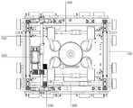
Fig. 1 is a schematic view of the overall structure of a single-power cable-stayed and jacked sixteen-wheel four-way shuttle vehicle;
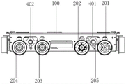
FIG. 2 is a schematic structural diagram of a single-power cable-stayed jacking sixteen-wheel four-way shuttle vehicle according to the present invention;
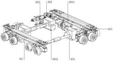
FIG. 3 is a schematic structural view of a single-power cable-stayed jacking sixteen-wheel four-way shuttle vehicle according to the present invention;
FIG. 4 is a left side view schematic structural view of a single-power cable-stayed jacking sixteen-wheel four-way shuttle vehicle according to the present invention;
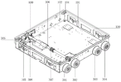
FIG. 5 is a schematic perspective view of a single-power cable-stayed jacking sixteen-wheel four-way shuttle vehicle according to the present invention;
fig. 6 is a schematic view of an upward assembly structure of a central spur gear, a central helical gear and a worm in a single-power cable-stayed jacking sixteen-wheel four-way shuttle vehicle according to the invention;
FIG. 7 is a schematic view of a top-view assembly structure of a central spur gear, a central helical gear and a worm of the single-power cable-stayed jacking sixteen-wheel four-way shuttle vehicle according to the present invention;
FIG. 8 is a schematic view of a transmission structure of a power transmission mechanism in a single-power cable-stayed jacking sixteen-wheel four-way shuttle vehicle according to the present invention;
FIG. 9 is a schematic view of a transmission structure of a transverse output shaft of a single-power cable-stayed jacking sixteen-wheel four-way shuttle vehicle according to the present invention;
FIG. 10 is a schematic structural view of a supporting frame in the single-power cable-stayed jacking sixteen-wheel four-way shuttle vehicle according to the present invention;
fig. 11 is an assembly structure schematic diagram of a tensioning adjusting mechanism in the single-power cable-stayed jacking sixteen-wheel four-way shuttle vehicle;
wherein the reference symbols are:
100-support frame, 101-square assembly hole, 102-round assembly hole, 103-jacking guide pillar, 104-guide pillar fixing plate, 105-bearing seat;
200-a transverse walking driving mechanism, 201-a transverse driving wheel, 202-a first transverse driven wheel, 203-a second transverse driven wheel, 204-a third transverse driven wheel, 205-a transverse transmission belt, 206-a transverse transmission shaft and 207-a transverse motor;
300-a longitudinal walking driving mechanism, 301-a first longitudinal driving wheel, 302-a second longitudinal driving wheel, 303-a first longitudinal driven wheel, 304-a first longitudinal driven wheel, 305-a longitudinal transmission belt, 306-a longitudinal transmission shaft and 307-a longitudinal motor;
400-diagonal pulling reversing and jacking mechanism, 401-jacking transverse plate, 402-diagonal pulling jacking sliding block, 403-diagonal pulling jacking sliding block, 404-sliding table, 405-connecting rod, 406-transmission cam, 407-central straight gear, 408-central helical gear, 409-worm, 410-guide sliding chute;
500-power transmission mechanism, 501-driving motor, 502-cross reducer, 503-longitudinal main driving wheel, 504-transverse main rotating wheel, 505-transverse output shaft, 506-electromagnetic clutch, 5061-rotating wheel, 5062-electromagnetic pressure plate and 5063-driven wheel;
600-tension adjusting mechanism, 601-first tension wheel, 602-first fixing plate, 603-second tension wheel, 604-adjusting plate, 605-adjusting square hole, 606-second fixing plate.
Detailed Description
The present invention will be described in detail and specifically with reference to the following examples to facilitate better understanding of the present invention, but the following examples do not limit the scope of the present invention.
In some embodiments, as shown in fig. 1, a single-power cable-stayed and jacked sixteen-wheel four-way shuttle vehicle is provided, which includes a supporting frame 100, a transverse traveling driving mechanism 200, a longitudinal traveling driving mechanism 300, a cable-stayed reversing and jacking mechanism 400, a power transmission mechanism 500, a battery pack and a controller, wherein the transverse traveling driving mechanism 200, the longitudinal traveling driving mechanism 300, the cable-stayed reversing and jacking mechanism 400 and the power transmission mechanism 500 are mounted on the supporting frame 100.
In one embodiment, the supporting frame 100 is a whole formed by bending sheet metal and connecting local reinforcing ribs, so that the bearing capacity of the whole vehicle is greatly improved; the battery pack is used as a power source to improve the power of the whole vehicle, and can adopt a lithium ion rechargeable battery, a storage battery or any other energy storage battery to supply power for each functional power supply of the trolley; the controller is used as the brain of the whole vehicle to control the motion of the whole vehicle, the controller is electrically connected with the battery pack and the power transmission mechanism 500, the controller controls the trolley to flexibly and radially longitudinally or transversely walk, and the trolley is jacked and reversed by the diagonal-pulling reversing and jacking mechanism 400.
In some embodiments, as shown in fig. 2 and 3, the transverse walking driving mechanism 200 is used as an execution unit for transverse movement of a sixteen-wheel four-way shuttle, and includes a transverse driving wheel 201, a first transverse driven wheel 202, a second transverse driven wheel 203 and a third transverse driven wheel 204, which are respectively and symmetrically arranged at the front and rear sides of the supporting frame 100, wherein the transverse driving wheel 201, the first transverse driven wheel 202, the second transverse driven wheel 203 and the third transverse driven wheel 204 are respectively arranged at the front and rear sides of the supporting frame 100, so as to form a transverse 8-wheel vehicle body structure, and the transverse walking load-carrying capacity and the threshold-crossing capacity of the vehicle are improved.
In one embodiment, as shown in fig. 2 and 4, two transverse driving wheels 201 and two third transverse driven wheels 204 are respectively disposed at two ends of a transverse transmission shaft 206, the transverse transmission shaft 206 between the two transverse driving wheels 201 is a transverse output shaft of a driving shaft and a cross speed reducer 502; the transverse transmission shaft 206 between the third transverse driven wheels 204 is a connecting shaft. The transverse driving wheels 201 at two ends can be driven to rotate through the transverse transmission shaft 206, and a transverse coupling is arranged on the transverse transmission shaft 206; in order to improve the running stability of the trolley, the two third transverse driven wheels 204 are connected through a transverse transmission shaft 206 serving as a connecting shaft, so that the synchronous running of the third transverse driven wheels 204 on the two sides is synchronously ensured, and the transverse transmission shaft 206 serving as the connecting shaft can also be connected with a transverse output shaft of the cross-shaped speed reducer 502 through a synchronous belt, so that the front and back double-drive rotation is realized.
The working principle of the transverse walking driving mechanism 200 in the sixteen-wheel four-way shuttle vehicle is as follows: the transverse transmission shaft 206 is controlled to rotate by the power transmission mechanism 500, the transverse driving wheels 201 at two ends of the transverse transmission shaft 206 are synchronously driven to rotate, and the first transverse driven wheel 202, the second transverse driven wheel 203 and the third transverse driven wheel 204 on the supporting frame 100 are synchronously driven to rotate, so that the transverse walking of the sixteen-wheel four-way shuttle vehicle is realized.
In some embodiments, as shown in fig. 2 and 3, the longitudinal driving mechanism 300 is used as an execution unit for lateral movement of a sixteen-wheel four-way shuttle, and includes a first longitudinal driving wheel 301, a second longitudinal driving wheel 302, a first longitudinal driven wheel 303 and a second longitudinal driven wheel 304, which are respectively and symmetrically arranged on the left and right sides of the supporting frame 100, wherein the number of the first longitudinal driving wheel 301, the second longitudinal driving wheel 302, the first longitudinal driven wheel 303 and the second longitudinal driven wheel 304 is two, and the first longitudinal driving wheel, the second longitudinal driving wheel 302, the first longitudinal driven wheel 303 and the second longitudinal driven wheel 304 are symmetrically arranged on two sides of the supporting frame 100, so as to form a longitudinal 8-wheel body structure, and improve the load-carrying capacity and the threshold-passing capacity of longitudinal walking of the trolley.
In one embodiment, as shown in fig. 2 and 3, the first longitudinal driving wheel 301 and the second longitudinal driving wheel 302 on both sides are used as driving wheels and are respectively connected with the longitudinal transmission shaft 306 through a longitudinal transmission belt 305, and the longitudinal transmission shaft 306 is connected with the power transmission mechanism 500 through a transmission belt, and the longitudinal transmission shaft 306 is driven to rotate by the power transmission mechanism 500 through the transmission belt.
In one embodiment, in order to match 16 wheels, a transmission mechanism of the longitudinal wheels is optimized, the position of the longitudinal transmission shaft 306 is moved upwards, as shown in fig. 10 and 11, the side surface of the assembly structure of the longitudinal transmission shaft 306, the first longitudinal driving wheel 301 and the second longitudinal driving wheel 302 forms a triangular structure, on one hand, one longitudinal transmission shaft 306 is adopted to synchronously drive the first longitudinal driving wheel 301 and the second longitudinal driving wheel 302 to simultaneously rotate, on the other hand, the lifted longitudinal transmission shaft 306 can well stagger the inclined-pulling reversing and jacking mechanism 400 arranged below the lifted longitudinal transmission shaft 306, so that the design of the trolley is more compact and reasonable, and the space is saved.
In one embodiment, to provide the cart with better load carrying capacity, the 8 longitudinal wheels used on the longitudinal travel drive mechanism 300 are larger and larger than the 8 transverse wheels used on the transverse travel drive mechanism 200. Specifically, the diameter of the transversal driving wheel 201, the first transversal driven wheel 202, the second transversal driven wheel 203 and the third transversal driven wheel 204 is slightly smaller than that of the first longitudinal driving wheel 301, the second longitudinal driving wheel 302, the first longitudinal driven wheel 303 and the second longitudinal driven wheel 304, and the diameter ratio thereof is 1.1-1.
The operating principle of the longitudinal travel driving mechanism 300 in the sixteen-wheel four-way shuttle vehicle is as follows: the power transmission mechanism 500 drives the longitudinal transmission shaft 306 to rotate through a transmission belt, synchronously drives the first longitudinal driving wheel 301 and the second longitudinal driving wheel 302 at two ends of the longitudinal transmission shaft 306 to rotate, and synchronously drives the first longitudinal driven wheel 303 and the second longitudinal driven wheel 304 on the supporting frame 100 to rotate, so that the longitudinal walking of the sixteen-wheel four-way shuttle vehicle is realized, and the longitudinal transmission shaft 306 is provided with a longitudinal coupling. In addition, the driving belt is tensioned again after working for a period of time, and the tensioning adjusting mechanism 600 can move transversely to achieve the purpose of adjustment according to the tightness of the belt pulley.
In some embodiments, as shown in fig. 2, 5, 6 and 7, the diagonal-pulling reversing and jacking mechanism 400 is used as an execution unit for jacking and reversing the sixteen-wheel four-way shuttle, and includes jacking transverse plates 401 symmetrically arranged on the left and right sides of the supporting frame 100, and jacking shafts 402 respectively connected to the front and rear ends of the jacking transverse plates 401, that is, the jacking transverse plates 401 on both sides are respectively connected by the jacking shafts 402 at the front and rear ends, so as to realize the reversing action of the jacking transverse plates 401 and the traveling driving mechanism during the ascending and descending processes of the jacking shafts 402.
Specifically, as shown in fig. 2, fig. 5, fig. 6, and fig. 7, left and right ends of each jacking shaft 402 respectively pass through a jacking inclined hole 4031 in each diagonal jacking slider 403 to connect with the jacking transverse plates 401 at both ends, the diagonal jacking sliders 403 are arranged at the bottoms of the supporting frames 100 through sliding tables 404, the sliding tables 404 are fixedly arranged at the tops of the bottoms of the supporting frames 100, and lower end fasteners of the jacking sliders 403 are arranged in the sliding tables 404 and can only move back and forth along the sliding tables 404, so that the jacking shafts 402 arranged in the jacking sliders 403 are driven to ascend or descend by the jacking inclined holes 4031 in the process of moving the jacking sliders 403 back and forth.
In addition, each inclined pulling and jacking sliding block 403 is respectively eccentrically connected with a single transmission cam 406 through a connecting rod 405 in a one-to-one correspondence manner, the two transmission cams 406 on the left side and the right side are in meshed transmission connection with a central straight gear 407 in the middle, and the four transmission cams 406 are respectively arranged on the outer side of the central straight gear 407. The central spur gear 407 is connected with a transverse output shaft of the power transmission mechanism 500, and power is transmitted to the cable-stayed jacking sliding block 403 through the transmission cam 406 through the central spur gear 407, so that the cable-stayed jacking sliding block 403 is controlled to move back and forth along the sliding table 404.
In one embodiment, as shown in fig. 2, fig. 5, fig. 6, and fig. 7, four diagonal lifting sliders 403 are provided, and are respectively disposed at four corners of the support frame 100, and the structure and the operation principle of each diagonal lifting slider 403 are the same. The inclined pulling and jacking sliding block 403 is driven by the transverse driving motor 207 to move up and down relative to the supporting frame 100, and meanwhile, the transverse driving wheel 201, the first transverse driven wheel 202, the second transverse driven wheel 203 and the third transverse driven wheel 204 on two sides are driven by the jacking transverse plate 401 to lift up and down, so that the reversing functions of the transverse walking driving mechanism 200 and the longitudinal walking driving mechanism 300 are flexibly realized.
The operating principle of the diagonal pulling reversing and jacking mechanism 400 in the sixteen-wheel four-way shuttle vehicle is as follows: the power conveying mechanism 500 drives the central straight gear 407 to rotate through the worm 209, the central straight gear 407 synchronously drives four transmission cams 406 around for transmission, the transmission cams 406 drive the connecting rods 405 thereon to do eccentric motion while transmitting, each connecting rod 405 drives the corresponding cable-stayed jacking slide block 403 to move back and forth along the sliding table 404, the cable-stayed jacking slide blocks 403 synchronously drive the jacking shafts 402 therein to move up and down along the jacking inclined holes 4031 in the vertical direction in the front and back movement process, and then the jacking transverse plates 401 at the two ends of the jacking shafts 402 and the jacking platforms at the tops of the jacking transverse plates are driven to lift, so that the functions of trolley jacking and reversing are realized.
In some embodiments, as shown in fig. 2 and 8, the power transmission mechanism 500 includes a driving motor 501 and a cross reducer 502, a longitudinal output shaft of the cross reducer 502 is connected to the longitudinal transmission shaft 306, and transverse output shafts thereof are respectively connected to the transverse transmission shaft 206 and the central spur gear 407. Specifically, a longitudinal driving wheel 503 at the longitudinal output shaft end of the cross speed reducer 502 is used for controlling the longitudinal walking driving mechanism 300 to walk through a synchronous belt and the longitudinal transmission shaft 306. A transverse driving wheel 504 at the transverse d output shaft end of the cross speed reducer 502 is used for controlling the transverse walking driving mechanism 200 to walk through a synchronous belt and the transverse transmission shaft 206.
In addition, as shown in fig. 2 and fig. 8, a transverse output shaft 505 is further connected to the transverse output shaft end of the cross speed reducer 502, the transverse output shaft 505 is connected to the worm 209 through an electromagnetic clutch 506, and the rotation of the worm 209 is controlled through the transverse output shaft 505 and the electromagnetic clutch 506. This power transmission mechanism 500 adopts a driving motor 501 to realize the independent control to horizontal running drive mechanism 200, vertical running drive mechanism 300 and to draw switching-over and climbing mechanism 400 to one side through the structural design who adopts cross reduction gear 502, electromagnetic clutch 506 and worm 209, compares current jacking switching-over mechanism, has saved two motors, greatly reduced manufacturing cost.
In one embodiment, as shown in fig. 9, the electromagnetic clutch 506 includes a commercially available miniature electromagnetic clutch, which is an automatic electric appliance operated by electromagnetic attraction, and the detailed structure principle is not described herein. The electromagnetic clutch 506 comprises a rotating wheel 5061, an electromagnetic pressure plate 5062 and a driven wheel 5063, wherein the rotating wheel 5061 is connected with the end of the transverse output shaft 505, the driven wheel 5063 is connected with the end of the worm 209, the rotating wheel 5061 and the driven wheel 5063 are separated or combined through the electromagnetic pressure plate 5062 according to the working requirement, so that the power of the driving motor 501 is transmitted to the worm 209 through the transverse output shaft 505 and the electromagnetic clutch 506, the worm 209 controls the central bevel gear 408 and the central spur gear 407 to rotate or stop, and then the jacking control of the diagonal-pulling jacking slider 403 is realized.
In some embodiments, as shown in fig. 9, the supporting frame 100 is a whole body formed by bending a sheet metal and partially reinforcing ribs, four square mounting holes 101 for mounting transverse wheels are respectively formed on the front and rear side walls of the supporting frame 100, and four circular mounting holes 102 for mounting longitudinal wheels are respectively formed on the left and right side walls of the supporting frame 100.
In one embodiment, as shown in fig. 2, 4 and 5, the transversal driving wheel 201 and the third transversal driven wheel 204 on both sides are connected by the transversal driving shaft 206 passing through the horizontal lifting plate 401 and arranged corresponding to the square assembly hole 101; the wheel shafts of the first transverse driven wheel 202 and the second transverse driven wheel 203 respectively pass through the corresponding square assembly holes 101 to be connected with the jacking transverse plate 401. In addition, in order to match the functions of inclined pulling and reversing and the lifting and reversing of the lifting mechanism 400, the transverse driving wheel 201, the first transverse driven wheel 202, the second transverse driven wheel 203 and the third transverse driven wheel 204 can perform up-and-down limiting lifting in the corresponding square assembly hole 101 along with the lifting transverse plate 401.
In one embodiment, as shown in fig. 2, 3 and 5, the axles of the first longitudinal driving wheel 301 and the second longitudinal driving wheel 302 respectively pass through the corresponding circular assembling holes 102 to be connected with the longitudinal transmission shafts 306, and the longitudinal transmission shafts 306 drive the first longitudinal driving wheel 301 and the second longitudinal driving wheel 302 to synchronously rotate through the first longitudinal transmission belt 308, so that the carrying capacity of the trolley is improved; in addition, the axles of the first longitudinal driving wheel 301 and the second longitudinal driving wheel 302 are respectively arranged through the circular assembling holes 102 and fixedly connected to the bottom of the supporting frame 100 through the bearing seats 105, so that the stability of the first longitudinal driving wheel 301 and the second longitudinal driving wheel 302 in the rotating process is ensured.
In one embodiment, as shown in fig. 2, 3 and 5, the first longitudinal driven wheel 303 and the second longitudinal driven wheel 304 are used as driven wheels, and mainly play a role of supporting and guiding in the driven operation of the supporting frame 100, and the first longitudinal driven wheel 303 and the second longitudinal driven wheel 304 are fixedly arranged in the corresponding circular mounting holes 102.
In some embodiments, as shown in fig. 2, 4 and 5, the wheel mounting structure of the sixteen-wheel four-way shuttle vehicle is optimized, and the first transverse driven wheel 202 is used as an auxiliary driving wheel of the vehicle, so that the transverse ground-holding and threshold-passing capacity of the vehicle is further improved. Specifically, the transverse driving wheel 201 is connected to the first transverse driven wheel 202 on the same side through the second transverse transmission belt 205, and the power of the transverse driving wheel 201 is transmitted to the first transverse driven wheel 202 through the second transverse transmission belt 205, so as to synchronously drive the first transverse driven wheel 202 to rotate.
In addition, according to the actual running requirement of the trolley, the third transverse driven wheel 204 on the same side can be connected through the second transverse transmission belt 205, and the third transverse driven wheel 204 is a linkage mechanism of the transverse driving wheel 201, so that the transverse walking stability and the ground gripping and threshold passing capacity of the trolley are further improved.
In some embodiments, as shown in fig. 1, 10 and 11, in order to ensure the stability of the power transmission of the longitudinal walking drive mechanism 300, the sixteen-wheel four-way shuttle vehicle further includes a tension adjusting mechanism 600 disposed outside the first longitudinal driving belt 308, and the tension adjusting mechanism 600 optimizes the connection between the first longitudinal driving belt 308 and the first longitudinal driving wheel 301 and the second longitudinal driving wheel 302, so that the first longitudinal driving belt 308 is more convenient to install.
In one embodiment, as shown in fig. 11, the tension adjusting mechanism 600 includes a first tension wheel 601 and a second tension wheel 603 disposed to be attached to the outer side of the first longitudinal transmission belt 308, the first tension wheel 601 is fixedly disposed on the inner side wall of the supporting frame 100 through a first fixing plate 602, the first tension wheel 601 is fixed and is always located between the first tension wheel 601 and the longitudinal transmission shaft 306, and is always attached to the first longitudinal transmission belt 308; the second tensioning wheel 603 can be movably disposed on the inner sidewall of the supporting frame 100 through the adjusting plate 604, and the second tensioning wheel 603 can generate a relative displacement towards the longitudinal transmission shaft 306 relative to the second tensioning wheel 603 under the adjusting action of the adjusting plate 604, and tightly press and attach to the other end face of the first longitudinal transmission belt 308, so as to form a tensioning state for the first longitudinal transmission belt 308; or to move the second tensioning wheel 603 away from the longitudinal drive shaft 306 to disengage it from the first longitudinal drive belt 308, thereby removing the tension from the first longitudinal drive belt 308.
In one embodiment, as shown in fig. 11, an adjusting square hole 605 is horizontally formed in the adjusting plate 604, and is movably fixed on the inner side wall of the supporting frame 100 through a bolt penetrating through the adjusting square hole 605, the adjusting square hole 605 plays a certain limiting role under the action of the bolt, and the length of the adjusting square hole 605 determines the left-right adjustable distance of the second tension wheel 603, so as to meet the requirement of tensioning the first longitudinal transmission belt 308.
In one embodiment, as shown in fig. 11, the distal end of the adjusting plate 604 is adjustably connected to the second fixing plate 606 by an adjusting nut and a bolt, the adjusting plate 604 and the second tension wheel 603 thereon can be controlled to move left and right along the length direction of the adjusting square hole 605 by the adjusting nut and the bolt, so as to adjust the tension of the first longitudinal transmission belt 308, and the second fixing plate 606 is fixed on the inner side wall of the supporting frame 100. The adjusting plate 604 and the second fixing plate 606 are both L-shaped plates, the side end surfaces of the L-shaped plates are arranged oppositely, the adjusting nuts and the bolts are arranged on the L-shaped plates arranged oppositely, the adjusting mode of the adjusting nuts and the bolts is realized by adopting the conventional structure, and the details are omitted here.
In one embodiment, as shown in fig. 5, the cable-stayed jacking sliding block 403 is transversely provided with a left-right through jacking inclined hole 4031, and the inner end surface is provided with a movable hole 4032. The inclined jacking hole 4031 is inclined at an angle of 5-85 degrees relative to the horizontal plane. Preferably, the inclined angle of the jacking inclined hole 342 is 20-80 degrees; further preferably, the inclined jacking hole 4031 is inclined at an angle of 35-65 °; more preferably, the inclined angle of the jacking inclined hole 4031 is 35-65 degrees; more preferably, the inclined angle of the inclined jacking hole 4031 is 40-45 degrees.
In one embodiment, in order to improve the stability of the relative movement between the jacking shaft 402 and the cable-stayed jacking sliding block 403, a roller bearing matched with the jacking shaft 402 is arranged in the inclined jacking hole 4031 of the cable-stayed jacking sliding block 403. One end of the connecting rod 405 is hinged in the movable hole 4032 through a pin shaft, the other end of the connecting rod 405 is hinged to the cam 406 through a pin shaft, and the front connecting rod and the rear connecting rod 405 are arranged in a central symmetry manner.
In one embodiment, as shown in fig. 6 and 7, a central helical gear 408 is coaxially arranged at the bottom of the central spur gear 407, the central helical gear 408 is connected with a longitudinal output shaft of the cross speed reducer 502 through a worm 409 arranged at one side of the central helical gear 408, and the cross speed reducer 502 is connected with the transverse driving motor 207.
In one embodiment, as shown in fig. 10, in order to ensure the stability of the diagonal-pulling and steering and jacking mechanism 400 during jacking and steering, the jacking cross plate 401 is connected with the jacking guide posts 103 at four corners of the supporting frame 100 in a vertically sliding manner through guide chutes 410 formed at two ends of the jacking cross plate 401, and two ends of the jacking cross plate 401 can slide along the jacking guide posts 103 during lifting, so that the defect that the jacking cross plate 401 shakes left and right during jacking is avoided; and the upper and lower both ends of jacking guide pillar 103 are respectively through guide pillar fixed plate 104 fixed connection braced frame 100, and the guide pillar fixed plate 104 that upper and lower both ends set up plays limiting displacement to the lift of jacking diaphragm 401 simultaneously.
The single-power cable-stayed jacking sixteen-wheel four-way shuttle vehicle provided by the invention adopts 8 wheels on each side to form a structural design of a 16-wheel two-way walking trolley, so that the load-carrying capacity and the over-threshold capacity of the trolley are greatly improved; the cable-stayed reversing and jacking mechanism realizes the linkage lifting action of the jacking shaft by adopting a linkage mode of the transmission cam and the cable-stayed jacking slide block, the transmission efficiency is high, and the pressure angle is unchanged; the diagonal jacking sliding blocks arranged at four corners are connected through two transmission cams, so that the stress is uniform, and the structure operation is stable; the diagonal-pulling reversing and jacking mechanism, the transverse walking driving mechanism and the longitudinal walking driving mechanism are in linkage control and share one driving motor, and compared with the existing diagonal-pulling reversing mechanism, the transverse walking driving mechanism saves two motors, and the production cost is greatly reduced. The single-power cable-stayed jacking sixteen-wheel four-way shuttle vehicle has compact structural design, thereby not only reducing the cost, but also saving the space; and the whole weight and volume of the trolley are reduced, and the operation capacity and the cargo storage and taking efficiency are improved.
The embodiments of the present invention have been described in detail, but the embodiments are merely examples, and the present invention is not limited to the embodiments described above. Any equivalent modifications and substitutions for the present invention are within the scope of the present invention for those skilled in the art. Accordingly, equivalent alterations and modifications are intended to be included within the scope of the present invention, without departing from the spirit and scope of the invention.
Claims (5)
1. The utility model provides a sixteen round quadriversal shuttle of single power cable-stayed jacking, which is characterized in that, include braced frame (100) and install in horizontal travel driving mechanism (200), vertical travel driving mechanism (300) on braced frame (100), draw switching-over and climbing mechanism (400) and power conveying mechanism (500) to one side, wherein:
the transverse walking driving mechanism (200) comprises transverse driving wheels (201), a first transverse driven wheel (202), a second transverse driven wheel (203) and a third transverse driven wheel (204) which are respectively and symmetrically arranged at the front side and the rear side of the supporting frame (100), and the two transverse driving wheels (201) are connected through a transverse transmission shaft (206);
the longitudinal walking driving mechanism (300) comprises a first longitudinal driving wheel (301), a second longitudinal driving wheel (302), a first longitudinal driven wheel (303) and a second longitudinal driven wheel (304) which are respectively and symmetrically arranged at the left side and the right side of the supporting frame (100), and the first longitudinal driving wheel (301) and the second longitudinal driving wheel (302) at the two sides are respectively connected with a longitudinal transmission shaft (306) through a longitudinal transmission belt (305); and
the cable-stayed reversing and jacking mechanism (400) comprises jacking transverse plates (401) symmetrically arranged on the left side and the right side of the supporting frame (100) and jacking shafts (402) respectively connected with the front end and the rear end of the jacking transverse plates (401), the left end and the right end of each jacking shaft (402) respectively penetrate through a jacking inclined hole (4031) in a cable-stayed jacking sliding block (403) to connect with the jacking transverse plates (401) at the two ends, and the cable-stayed jacking sliding block (403) is arranged at the bottom of the supporting frame (100) through a sliding table (404); each cable-stayed jacking sliding block (403) is eccentrically connected with a transmission cam (406) in a one-to-one correspondence manner through a connecting rod (405), and the four transmission cams (406) are in meshed connection with a central straight gear (407) in the middle; the cable-stayed jacking sliding block (403) is transversely provided with a jacking inclined hole (4031) which is communicated from left to right, and the end surface of the inner side of the cable-stayed jacking sliding block is provided with a movable hole (4032); the inclined jacking hole (4031) has an inclination angle of 5-85 degrees relative to the horizontal plane, and a roller bearing matched with the jacking shaft (402) is assembled in the inclined jacking hole;
the power transmission mechanism (500) comprises a driving motor (501) and a cross speed reducer (502), wherein a longitudinal output shaft of the cross speed reducer (502) is connected with the longitudinal transmission shaft (306), and a transverse output shaft of the cross speed reducer is respectively connected with the transverse transmission shaft (206) and the central straight gear (407);
one end of each connecting rod (405) is hinged in the corresponding movable hole (4032) through a pin shaft, the other end of each connecting rod is hinged to the corresponding cam (406) through a pin shaft, and the two adjacent connecting rods (405) are symmetrically arranged;
the bottom of the central straight gear (407) is coaxially provided with a central helical gear (408), and the central helical gear (408) is connected with a transverse output shaft of a cross speed reducer (502) through a worm (409) arranged on one side of the central helical gear through an electromagnetic clutch (506);
four square assembly holes (101) are respectively seted up to the front and back both sides wall of braced frame (100), four circular assembly holes (102) are respectively seted up to the left and right sides wall of braced frame (100), wherein:
the transverse driving wheel (201) and the third transverse driven wheel (204) on two sides are respectively connected through the transverse transmission shaft (206) which penetrates through the jacking transverse plate (401) and is arranged corresponding to the square assembly hole (101), and wheel shafts of the first transverse driven wheel (202) and the second transverse driven wheel (203) respectively penetrate through the corresponding square assembly hole (101) and are connected with the jacking transverse plate (401);
the wheel shafts of the first longitudinal driving wheel (301) and the second longitudinal driving wheel (302) respectively penetrate through the circular assembly holes (102) and are connected with the bottom of the supporting frame (100) through a bearing seat (105), and the first longitudinal driven wheel (303) and the second longitudinal driven wheel (304) are arranged in the corresponding circular assembly holes (102).
2. The single-power cable-stayed and jacked sixteen-wheel four-way shuttle car according to claim 1, characterized in that the transverse driving wheel (201) is connected with the first transverse driven wheel (202) on the same side through a transverse synchronous belt (205); and/or the third transverse driven wheel (204) on the same side is connected through a transverse synchronous belt (205).
3. The single-power cable-stayed jacking sixteen-wheel four-way shuttle car according to claim 1, wherein the jacking transverse plate (401) is vertically slidably connected with jacking guide pillars (103) at four corners of the supporting frame (100) through guide sliding grooves (410) formed in two ends of the jacking transverse plate, and the upper end and the lower end of each jacking guide pillar (103) are respectively fixedly connected with the supporting frame (100) through guide pillar fixing plates (104).
4. The single-power cable-stayed sixteen-wheel four-way shuttle car according to claim 1, further comprising a tension adjusting mechanism (600) arranged outside the longitudinal transmission belt (305), wherein:
the tensioning adjusting mechanism (600) comprises a first tensioning wheel (601) and a second tensioning wheel (603) which are attached to two sides of the longitudinal transmission belt (305), the first tensioning wheel (601) is fixedly arranged on the inner side wall of the supporting frame (100) through a first fixing plate (602), and the second tensioning wheel (603) is movably arranged on the inner side wall of the supporting frame (100) through an adjusting plate (604).
5. The single-power cable-stayed and jacking sixteen-wheel four-way shuttle car as claimed in claim 4, wherein an adjusting square hole (605) is horizontally formed in the adjusting plate (604), the adjusting square hole is movably fixed on the inner side wall of the supporting frame (100) through a bolt penetrating in the adjusting square hole (605), and one end of the adjusting square hole is adjustably connected with a second fixing plate (606) fixed on the inner side wall of the supporting frame (100) through an adjusting nut and a bolt.
Priority Applications (1)
| Application Number | Priority Date | Filing Date | Title |
|---|---|---|---|
| CN202110790005.9A CN113428544B (en) | 2021-07-13 | 2021-07-13 | Single-power cable-stayed jacking sixteen-wheel four-way shuttle |
Applications Claiming Priority (1)
| Application Number | Priority Date | Filing Date | Title |
|---|---|---|---|
| CN202110790005.9A CN113428544B (en) | 2021-07-13 | 2021-07-13 | Single-power cable-stayed jacking sixteen-wheel four-way shuttle |
Publications (2)
| Publication Number | Publication Date |
|---|---|
| CN113428544A CN113428544A (en) | 2021-09-24 |
| CN113428544B true CN113428544B (en) | 2022-10-25 |
Family
ID=77760164
Family Applications (1)
| Application Number | Title | Priority Date | Filing Date |
|---|---|---|---|
| CN202110790005.9A Active CN113428544B (en) | 2021-07-13 | 2021-07-13 | Single-power cable-stayed jacking sixteen-wheel four-way shuttle |
Country Status (1)
| Country | Link |
|---|---|
| CN (1) | CN113428544B (en) |
Families Citing this family (1)
| Publication number | Priority date | Publication date | Assignee | Title |
|---|---|---|---|---|
| CN114435821B (en) * | 2021-12-10 | 2024-03-19 | 隆链智能科技(上海)有限公司 | Four-way transmission mechanism |
Family Cites Families (9)
| Publication number | Priority date | Publication date | Assignee | Title |
|---|---|---|---|---|
| CN105346125A (en) * | 2015-12-03 | 2016-02-24 | 宁波博信机械制造有限公司 | Double-point eccentric gear type multi-linkage mechanism for punch press |
| CN206828516U (en) * | 2017-06-13 | 2018-01-02 | 四川农业大学 | A kind of subregion microculture shaking table |
| CN107685354A (en) * | 2017-09-29 | 2018-02-13 | 瑞安市鹏洲印刷机械有限公司 | A kind of vertical automatic impression machine |
| CN209147597U (en) * | 2018-10-30 | 2019-07-23 | 温州杰凯汽车部件有限公司 | A kind of auto parts and components drying equipment |
| DE102019124537A1 (en) * | 2019-09-12 | 2021-03-18 | Fraunhofer-Gesellschaft zur Förderung der angewandten Forschung e.V. | Vehicle for the automatic operation of a storage rack that has several rows of running rails, one above the other and in alignment with one another |
| CN212558100U (en) * | 2020-05-19 | 2021-02-19 | 昆明欧迈科技有限公司 | Four-way shuttle wheel reversing mechanism |
| CN212576371U (en) * | 2020-06-04 | 2021-02-23 | 东莞市康柏测量仪器有限公司 | Efficient ceramic waste breaker |
| CN112093349B (en) * | 2020-09-15 | 2022-01-18 | 隆链智能科技(上海)有限公司 | Jacking linkage type sixteen-wheel four-way shuttle |
| CN215363151U (en) * | 2021-07-13 | 2021-12-31 | 隆链智能科技(上海)有限公司 | Single-power sixteen-wheel four-way shuttle |
-
2021
- 2021-07-13 CN CN202110790005.9A patent/CN113428544B/en active Active
Also Published As
| Publication number | Publication date |
|---|---|
| CN113428544A (en) | 2021-09-24 |
Similar Documents
| Publication | Publication Date | Title |
|---|---|---|
| CN112079030B (en) | Transverse electromagnetic linkage type sixteen-wheel four-way shuttle | |
| CN112093349B (en) | Jacking linkage type sixteen-wheel four-way shuttle | |
| CN112079031B (en) | Diagonal-pulling jacking reversing type sixteen-wheel four-way shuttle | |
| CN202897946U (en) | Motor train unit air spring replacing device | |
| WO2019114170A1 (en) | Vehicle lifting mechanism and automatic power conversion system | |
| CN111591659A (en) | Four-way walking trolley | |
| CN106672853B (en) | A kind of full-bearing type car power assembly assembly method and tooling | |
| CN113428544B (en) | Single-power cable-stayed jacking sixteen-wheel four-way shuttle | |
| CN215363151U (en) | Single-power sixteen-wheel four-way shuttle | |
| CN215515238U (en) | Linkage type sixteen-wheel four-way shuttle | |
| CN114751125A (en) | Four-way shuttle based on control of inner cam profile | |
| CN112027462A (en) | Longitudinal electromagnetic linkage type sixteen-wheel four-way shuttle | |
| CN112093350A (en) | Sixteen-wheel four-way shuttle | |
| CN113306945B (en) | Cam lifting type sixteen-wheel four-way shuttle | |
| CN113135375A (en) | Novel four-way shuttle | |
| CN110817491B (en) | Intelligent coal leveling device for coal loading | |
| CN108609197A (en) | A kind of ski type helicopter ground omnidirectional mobile device | |
| CN215946644U (en) | Staircase cargo carrying vehicle | |
| CN212291499U (en) | Four-way walking trolley | |
| CN212374153U (en) | Heavy four-way shuttle | |
| CN212639812U (en) | Novel elevator | |
| CN112046641B (en) | Aluminum alloy plate transport vehicle with limiting plate capable of automatically lifting along with change of moving speed | |
| CN114906530B (en) | Longitudinal linkage type reversing jacking mechanism of four-way vehicle | |
| CN207725371U (en) | A kind of electric vehicle battery replacement device | |
| CN216331668U (en) | Transfer device is used in buncher production |
Legal Events
| Date | Code | Title | Description |
|---|---|---|---|
| PB01 | Publication | ||
| PB01 | Publication | ||
| SE01 | Entry into force of request for substantive examination | ||
| SE01 | Entry into force of request for substantive examination | ||
| GR01 | Patent grant | ||
| GR01 | Patent grant | ||
| PE01 | Entry into force of the registration of the contract for pledge of patent right | ||
| PE01 | Entry into force of the registration of the contract for pledge of patent right |
Denomination of invention: A single power cable-stayed jack up sixteen wheel four-way shuttle car Effective date of registration: 20230926 Granted publication date: 20221025 Pledgee: Agricultural Bank of China Limited Shanghai Huangpu Sub branch Pledgor: LONLINK INTELLIGENT TECHNOLOGY (SHANGHAI) CO.,LTD. Registration number: Y2023310000607 |