CN113405926B - Hardness detection device is used in optical glass production - Google Patents
Hardness detection device is used in optical glass production Download PDFInfo
- Publication number
- CN113405926B CN113405926B CN202110954757.4A CN202110954757A CN113405926B CN 113405926 B CN113405926 B CN 113405926B CN 202110954757 A CN202110954757 A CN 202110954757A CN 113405926 B CN113405926 B CN 113405926B
- Authority
- CN
- China
- Prior art keywords
- plate
- upright post
- pipe
- fixedly mounted
- optical glass
- Prior art date
- Legal status (The legal status is an assumption and is not a legal conclusion. Google has not performed a legal analysis and makes no representation as to the accuracy of the status listed.)
- Active
Links
Images


Classifications
-
- G—PHYSICS
- G01—MEASURING; TESTING
- G01N—INVESTIGATING OR ANALYSING MATERIALS BY DETERMINING THEIR CHEMICAL OR PHYSICAL PROPERTIES
- G01N3/00—Investigating strength properties of solid materials by application of mechanical stress
- G01N3/30—Investigating strength properties of solid materials by application of mechanical stress by applying a single impulsive force, e.g. by falling weight
- G01N3/303—Investigating strength properties of solid materials by application of mechanical stress by applying a single impulsive force, e.g. by falling weight generated only by free-falling weight
-
- G—PHYSICS
- G01—MEASURING; TESTING
- G01N—INVESTIGATING OR ANALYSING MATERIALS BY DETERMINING THEIR CHEMICAL OR PHYSICAL PROPERTIES
- G01N3/00—Investigating strength properties of solid materials by application of mechanical stress
- G01N3/02—Details
-
- G—PHYSICS
- G01—MEASURING; TESTING
- G01N—INVESTIGATING OR ANALYSING MATERIALS BY DETERMINING THEIR CHEMICAL OR PHYSICAL PROPERTIES
- G01N3/00—Investigating strength properties of solid materials by application of mechanical stress
- G01N3/40—Investigating hardness or rebound hardness
-
- G—PHYSICS
- G01—MEASURING; TESTING
- G01N—INVESTIGATING OR ANALYSING MATERIALS BY DETERMINING THEIR CHEMICAL OR PHYSICAL PROPERTIES
- G01N2203/00—Investigating strength properties of solid materials by application of mechanical stress
- G01N2203/0058—Kind of property studied
- G01N2203/0076—Hardness, compressibility or resistance to crushing
Abstract
The invention discloses a hardness detection device for optical glass production, which comprises an upright post, wherein a blanking pipe is arranged on the upright post through a bearing mechanism, two elastic through holes are formed in the upright post through a bottom partition plate and a top partition plate, a vertical toothed bar is arranged in the upright post through a sliding mechanism and a bottom plate in a matching manner, a transverse toothed bar is arranged in the upright post through a limiting groove and a limiting block in a matching manner in a sliding manner, a push plate is fixedly arranged between the transverse toothed bar and the upright post through a reset spring, a transmission gear meshed with the transverse toothed bar and the vertical toothed bar is rotatably arranged in the upright post, a storage pipe is fixedly arranged between the bottom partition plate and the top partition plate, and a material return pipe is arranged on the upright post through a falling mechanism. Has the advantages that: can carry out the multiple spot resistance to compression detection under the fixed effect of not influencing optical glass to can carry out the anti striking hardness detection of multiposition, multiple height to it, and can accomplish falling ball's recovery and replenishment automatically, efficiency is higher and the testing result is more accurate.
Description
Technical Field
The invention relates to the technical field of optical glass, in particular to a hardness detection device for optical glass production.
Background
The optical glass is special glass commonly used in optical instruments, the optical glass is usually detected by a hardness detection device after production is finished, so that whether the compression hardness and the impact resistance hardness of the optical glass reach the standard or not is judged, and through retrieval, the invention discloses a hardness detection device for glass production, which comprises a base, wherein a pressure sensor is installed on the left side inside the base, a support column is arranged at the lower end inside the frame, a plastic film is arranged on the upper side of the support column, two ends of the upper side of the base are both connected with first slide bars, and connecting columns are fixed on the upper sides of the slide blocks;
the above device still has the following disadvantages when in use:
1. the device adopts a mode of clamping and extruding the glass to detect the hardness, the mode can only detect the compression resistance hardness of the optical glass, but can not detect the impact resistance hardness of the optical glass, and the detection range is narrow;
2. when the existing part of devices are used for detecting the hardness of the anti-device of glass, falling balls used for impacting the glass cannot be collected, supplemented and reused, the falling height and falling position of the falling balls cannot be changed, the detected experimental data are less, and the detection result is lower in precision;
therefore, it is necessary to design a hardness testing device for optical glass production to solve the above problems.
Disclosure of Invention
The invention aims to solve the problems in the prior art and provides a hardness detection device for optical glass production.
In order to achieve the purpose, the invention adopts the following technical scheme:
a hardness detection device for optical glass production comprises an upright post, wherein a blanking pipe is installed on the upright post through a bearing mechanism, two elastic through holes are formed in the upright post through a bottom partition plate and a top partition plate, a vertical toothed bar is installed in the upright post through the matching of a sliding mechanism and a bottom plate, a transverse toothed bar is installed in the upright post through the matching of a limiting groove and a limiting block in a sliding manner, a push plate is fixedly installed between the transverse toothed bar and the upright post through a reset spring, a transmission gear meshed with the transverse toothed bar and the vertical toothed bar is installed in the upright post in a rotating manner, a storage pipe is fixedly installed between the bottom partition plate and the top partition plate, and a material return pipe is installed on the upright post through a falling mechanism;
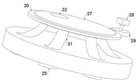
the loading mechanism comprises a loading disc fixedly mounted on the upright post, a supporting plate is fixedly mounted on the loading disc through a plurality of supporting columns, a connecting pipe is fixedly mounted on the loading disc and communicated with the blanking pipe, a plurality of fixed plates are fixedly mounted on the loading disc, a moving plate is mounted on each fixed plate through a pressing structure, and a hardness ball is fixedly mounted on each moving plate through a hydraulic rod;
the pressing structure comprises a threaded rod which is installed on a fixed plate in a threaded manner, a limiting rotating shaft is fixedly installed at the bottom of the threaded rod, a movable plate is rotatably installed on the limiting rotating shaft, a limiting spring is fixedly installed between the movable plate and the fixed plate, and a pressing column is fixedly installed on the movable plate;
drop the mechanism and establish the lift ring on the stand including sliding sleeve, and install location structure between lift ring and the stand, there is the roof through falling a set fixed mounting on the lift ring, and feed back pipe fixed mounting between roof and stand, fall and fall the interior fixed mounting of dish and have arc ring, connection pad, and fixed mounting has a plurality of arc pipes between arc ring and the connection pad, every arc pipe and fall equal fixed mounting between the dish and fall the pipe, install transmission structure on the roof.
Furthermore, the sliding mechanism comprises a trapezoidal sliding block fixedly mounted on the bottom plate, a trapezoidal sliding groove matched with the trapezoidal sliding block is formed in the stand column, and the vertical toothed bar is fixedly mounted on the bottom plate.
Further, location structure includes the connecting block of fixed mounting on the lifting ring, there are scale bar, locating lever through two installation pole fixed mounting on the stand, and set up on the connecting block with scale bar, locating lever matched with slide opening, install the locating pin through the locating plate screw thread on the connecting block, and set up a plurality of locating holes with locating pin matched with on the locating lever.
Further, the transmission structure includes fixed mounting at the gear motor of roof lower part, fixed mounting has drive gear on gear motor's the drive end, rotate through changeing the roller on the roof and install down the charging tray, and the upper end of every arc pipe all laminates mutually with lower charging tray, fixed mounting has the outer ring gear with drive gear engaged with on the charging tray down, the intercommunicating pore has been seted up on the charging tray down.
Furthermore, a supplementary tube is fixedly installed on the top plate, and a holding rod is fixedly installed on the connecting block.
Compared with the prior art, the invention has the advantages that:
1: the device can stably press and fix the optical glass to be detected, can detect the multipoint compression hardness of the optical glass on the premise of not influencing the fixed effect of the optical glass, and is simple to operate and convenient and accurate to detect.
2: the device can flexibly change the falling height of the falling ball and the falling of the falling ball without being assembled, so that the impact hardness test of multiple positions and multiple heights can be carried out on the optical glass, the detection data sample can be increased, and the detection precision is increased.
3: the device can automatically recover the last falling ball after the collision is finished, and can automatically supplement the next falling ball to the falling disc, so that the time for picking and placing the falling ball can be saved, and the falling ball can be prevented from being lost.
In conclusion, the invention can carry out multi-point compression resistance detection without influencing the fixing effect of the optical glass, can carry out multi-position and multi-height impact resistance hardness detection on the optical glass, can automatically complete the recovery and supplement of the falling ball, and has higher efficiency and more accurate detection result.
Drawings
Embodiments of the invention are described in further detail below with reference to the attached drawing figures, wherein:
FIG. 1 is a schematic structural view of a hardness testing apparatus for optical glass production according to the present invention;
FIG. 2 is an enlarged view of the connection structure of the carrier tray and the upper portion of the carrier tray in FIG. 1;
FIG. 3 is an enlarged view of the connection structure between the support plate and the blanking tube in FIG. 2;
fig. 4 is an enlarged view of a connection structure of the fixing plate and an upper portion thereof in fig. 2;
FIG. 5 is an enlarged view of the lifting ring, the drop plate and a portion of the connection structure therebetween of FIG. 1;
FIG. 6 is an enlarged view of the lifting ring, the connecting block and a portion of the connecting structure therebetween shown in FIG. 1;
FIG. 7 is an enlarged view of the drop plate of FIG. 5 with a portion of the drop plate attached thereto;
FIG. 8 is a schematic view of the internal structure of the dropout tray of FIG. 7;
FIG. 9 is an enlarged view of the connection structure between the lower tray and the speed reducing motor in FIG. 8;
FIG. 10 is a schematic view of the connection between the blanking tray and the plurality of arc-shaped conduits in FIG. 9;
FIG. 11 is a cross-sectional view of the internal structure of the column of FIG. 1;
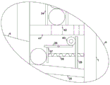
fig. 12 is an enlarged view of a portion a in fig. 11.
In the figure: the device comprises a vertical column 1, a bearing plate 2, a supporting plate 3, a blanking tube 4, a lifting ring 5, a falling plate 6, a top plate 7, a supplementary tube 8, a material return tube 9, a connecting block 10, a scale rod 11, a positioning rod 12, a fixing plate 13, a connecting tube 14, a threaded rod 15, a limit rotating shaft 16, a moving plate 17, a hydraulic rod 18, a hardness ball 19, a pressing column 20, a positioning plate 21, a positioning pin 22, a positioning hole 23, a holding rod 24, a falling tube 25, an arc-shaped ring 26, a blanking plate 27, a speed reduction motor 28, a driving gear 29, an outer toothed ring 30, an arc-shaped guide tube 31, a communication hole 32, a top clapboard 33, a storage tube 34, a bottom plate 35, a transverse toothed rod 36, a pushing plate 37, a return spring 38, a vertical toothed rod 39, a transmission gear 40, a bottom clapboard 41 and an elastic through hole 42.
Detailed Description
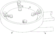
Referring to fig. 1-4, a hardness detection device for optical glass production comprises an upright post 1, wherein a blanking pipe 4 is arranged on the upright post 1 through a bearing mechanism;
the following points are notable:
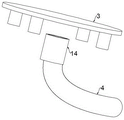
1. bear the mechanism and include that fixed mounting bears dish 2 on stand 1, bear and to have layer board 3 through a plurality of support column fixed mounting on dish 2, bear and to coil 2 and go up fixed mounting and have connecting pipe 14, and connecting pipe 14 is linked together with unloading pipe 4, bear and to coil 2 and go up fixed mounting and have a plurality of fixed plates 13, all install movable plate 17 through pressing the structure on every fixed plate 13.
2. The pressing structure comprises a threaded rod 15 which is installed on the fixed plate 13 in a threaded mode, a limiting rotating shaft 16 is fixedly installed at the bottom of the threaded rod 15, the moving plate 17 is rotatably installed on the limiting rotating shaft 16, a limiting spring is fixedly installed between the moving plate 17 and the fixed plate 13, and a pressing column 20 is fixedly installed on the moving plate 17;
optical glass to be detected is placed on layer board 3, rotates a plurality of threaded rods 15 and can drive a plurality of movable plates 17 and press post 20 decline, when pressing post 20 and drop to extrude the laminating mutually with optical glass's upper surface, can be with optical glass's firm centre gripping between pressing post 20 and layer board 3 promptly, makes it can not take place to remove and squint when carrying out resistance to compression and anti striking detection.
3. The movable plate 17 is fixedly provided with the hardness balls 19 through the hydraulic rods 18, after the optical glass is fixed, the hydraulic rods 18 can be started to drive the hardness balls 19 to descend and extrude the optical glass, and the compression hardness of the optical glass can be detected on the premise that the fixing effect of the optical glass is not changed.
Referring to fig. 1 and 5-10, a feed back pipe 9 is arranged on the upright post 1 through a dropping mechanism;
the following points are notable:
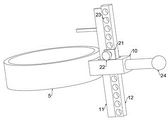
1. the falling mechanism comprises a lifting ring 5 which is sleeved on the upright post 1 in a sliding way, a positioning structure is arranged between the lifting ring 5 and the upright post 1, the lifting ring 5 can flexibly move up and down on the upright post 1 to adjust the height position, and the falling height of the falling ball can be flexibly adjusted, so that the falling impact force of the falling ball can be changed.
2. The location structure includes connecting block 10 of fixed mounting on lifting ring 5, there are scale bar 11 through two installation pole fixed mounting on stand 1, locating lever 12, and seted up on connecting block 10 with scale bar 11, locating lever 12 matched with sliding hole, install locating pin 22 through locating plate 21 screw thread on connecting block 10, and set up a plurality ofly on locating lever 12 with locating pin 22 matched with locating hole 23, after the height position adjustment of lifting ring 5 finishes, can rotate locating pin 22 and make in its screw in locating hole 23 of corresponding position in locating lever 12, can fix the height position of lifting ring 5.
3. The holding rod 24 is fixedly arranged on the connecting block 10, and an operator can hold the holding rod 24 to drive the lifting ring 5 to move up and down, so that the device is more convenient and trouble-saving.
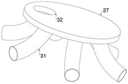
4. There is roof 7 through falling dish 6 fixed mounting on the lifting ring 5, and feed back pipe 9 fixed mounting between roof 7 and stand 1, falls and to fall in the dish 6 fixed mounting have arc ring 26, connection pad, and fixed mounting has a plurality of arc pipes 31 between arc ring 26 and the connection pad, every arc pipe 31 and fall and all fixed mounting have down pipe 25 between the dish 6.
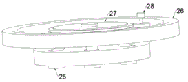
5. The top plate 7 is fixedly provided with the replenishing pipe 8, the top plate 7 is provided with a transmission structure, the transmission structure comprises a speed reducing motor 28 fixedly arranged at the lower part of the top plate 7, the driving end of the speed reducing motor 28 is fixedly provided with a driving gear 29, the top plate 7 is rotatably provided with a blanking disc 27 through a rotating roller, the upper end of each arc-shaped guide pipe 31 is attached to the blanking disc 27, the blanking disc 27 is fixedly provided with an outer gear ring 30 meshed with the driving gear 29, and the blanking disc 27 is provided with a communicating hole 32;
the falling ball enters the falling disc 6 through the material return pipe 9, falls into the arc-shaped ring 26, falls onto the blanking disc 27, enters the arc-shaped guide pipe 31 through the communicating hole 32 in the blanking disc 27, finally falls onto the optical glass to be detected on the bearing disc 2 through the falling pipe 25, and then can be used for impact detection on the optical glass.
After the last falling ball falls, the speed reducing motor 28 is started to drive the driving gear 29 to rotate with the outer toothed ring 30 meshed with the driving gear, the outer toothed ring 30 drives the lower tray 27 to rotate when rotating, so that the position of the communication hole 32 can be adjusted, the communication hole 32 rotates to the upper part of the next arc-shaped guide pipe 31, and the next falling ball falls through the next arc-shaped guide pipe 31 at the moment, so that the falling point of the falling ball on the optical glass can be changed, and the multipoint and multi-position anti-collision detection can be carried out.
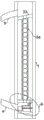
Referring to fig. 1 and 11-12, two elastic through holes 42 are formed in the upright post 1 through a bottom partition plate 41 and a top partition plate 33, a vertical toothed bar 39 is installed in the upright post 1 through the matching of a sliding mechanism and a bottom plate 35, a horizontal toothed bar 36 is installed in the upright post 1 through the matching of a limiting groove and a limiting block in a sliding manner, a push plate 37 is fixedly installed between the horizontal toothed bar 36 and the upright post 1 through a return spring 38, a transmission gear 40 meshed with the horizontal toothed bar 36 and the vertical toothed bar 39 is rotatably installed in the upright post 1, and a storage tube 34 is fixedly installed between the bottom partition plate 41 and the top partition plate 33;
the following points are notable:
1. slide mechanism includes the trapezoidal slider of fixed mounting on bottom plate 35, has seted up in the stand 1 with trapezoidal slider matched with trapezoidal spout, erect ratch 39 fixed mounting on bottom plate 35, slide mechanism is used for making bottom plate 35 and erect ratch 39 and can only slide from top to bottom in stand 1, and can not and take place skew and separation between the stand 1.
2. After the falling ball impacts the optical glass, the falling ball enters the upright post 1 through the communicating pipe 14 and the blanking pipe 4 and slides rapidly on the bottom plate 35, when the falling ball slides on the bottom plate 35, the falling ball impacts the push plate 37 to move horizontally, the push plate 37 drives the transverse toothed bar 36 on the push plate to move horizontally, when the transverse toothed bar 36 moves, the transmission gear 40 meshed with the transverse toothed bar is driven to rotate, when the transmission gear 40 rotates, the vertical toothed bar 39 meshed with the transmission gear is driven to move up and down, and therefore the bottom plate 35 and the falling ball on the bottom plate are pulled to rise;
the storage tube 34 is filled with a plurality of falling balls, when the falling balls on the bottom plate 35 rise to contact with the elastic through holes 42 on the bottom partition plate 41, the falling balls move upwards to press the elastic through holes 42 and finally enter the storage tube 34 through the elastic through holes 42, the falling balls at the uppermost part in the storage tube 34 are pressed by the lower part to enter the upper part of the top partition plate 33 through the elastic through holes 42 on the top partition plate 33, the falling balls passing through the top partition plate 33 enter the falling plate 6 along the top partition plate 33 and the material return pipe 9, the automatic supplement of the falling balls in the falling plate 6 can be completed, the time for recovering and supplementing the falling balls can be saved, and the impact test of the falling balls at the next time can be rapidly carried out.
Claims (5)
1. The hardness detection device for optical glass production comprises a stand column (1) and is characterized in that a blanking pipe (4) is installed on the stand column (1) through a bearing mechanism, two elastic through holes (42) are formed in the stand column (1) through a bottom partition plate (41) and a top partition plate (33), a vertical toothed rod (39) is installed in the stand column (1) through the matching of a sliding mechanism and a bottom plate (35), a transverse toothed rod (36) is installed in the stand column (1) through the matching of a limiting groove and a limiting block in a sliding manner, a push plate (37) is fixedly installed between the transverse toothed rod (36) and the stand column (1) through a reset spring (38), a transmission gear (40) meshed with the transverse toothed rod (36) and the vertical toothed rod (39) is installed in the stand column (1) in a rotating manner, and a storage pipe (34) is fixedly installed between the bottom partition plate (41) and the top partition plate (33), a material return pipe (9) is arranged on the upright post (1) through a falling mechanism;
the bearing mechanism comprises a bearing disc (2) fixedly mounted on an upright post (1), a supporting plate (3) is fixedly mounted on the bearing disc (2) through a plurality of supporting columns, a connecting pipe (14) is fixedly mounted on the bearing disc (2), the connecting pipe (14) is communicated with a discharging pipe (4), a plurality of fixing plates (13) are fixedly mounted on the bearing disc (2), a moving plate (17) is mounted on each fixing plate (13) through a pressing structure, and a hardness ball (19) is fixedly mounted on each moving plate (17) through a hydraulic rod (18);
the pressing structure comprises a threaded rod (15) which is installed on a fixed plate (13) in a threaded mode, a limiting rotating shaft (16) is fixedly installed at the bottom of the threaded rod (15), a moving plate (17) is rotatably installed on the limiting rotating shaft (16), a limiting spring is fixedly installed between the moving plate (17) and the fixed plate (13), and a pressing column (20) is fixedly installed on the moving plate (17);
falling mechanism establishes lift ring (5) on stand (1) including the slip cover, and installs location structure between lift ring (5) and stand (1), there is roof (7) through falling dish (6) fixed mounting on lift ring (5), and feed back pipe (9) fixed mounting between roof (7) and stand (1), fall dish (6) internal fixed mounting have arc ring (26), connection pad, and fixed mounting has a plurality of arc pipes (31) between arc ring (26) and the connection pad, every arc pipe (31) and fall equal fixed mounting have between dish (6) and fall pipe (25) that falls, install transmission structure on roof (7).
2. The hardness testing device for optical glass production according to claim 1, wherein the sliding mechanism comprises a trapezoidal sliding block fixedly mounted on the bottom plate (35), a trapezoidal sliding groove matched with the trapezoidal sliding block is formed in the upright column (1), and the vertical toothed bar (39) is fixedly mounted on the bottom plate (35).
3. The hardness testing device for optical glass production according to claim 1, wherein the positioning structure comprises a connecting block (10) fixedly mounted on the lifting ring (5), the upright column (1) is fixedly mounted with a scale rod (11) and a positioning rod (12) through two mounting rods, the connecting block (10) is provided with a sliding hole matched with the scale rod (11) and the positioning rod (12), the connecting block (10) is provided with a positioning pin (22) through a positioning plate (21) in a threaded manner, and the positioning rod (12) is provided with a plurality of positioning holes (23) matched with the positioning pin (22).
4. The hardness testing device for optical glass production according to claim 1, wherein the transmission structure comprises a speed reducing motor (28) fixedly mounted at the lower part of a top plate (7), a driving gear (29) is fixedly mounted at the driving end of the speed reducing motor (28), a blanking plate (27) is mounted on the top plate (7) through a rotary roller in a rotating manner, the upper end of each arc-shaped guide pipe (31) is attached to the blanking plate (27), an outer toothed ring (30) meshed with the driving gear (29) is fixedly mounted on the blanking plate (27), and a communicating hole (32) is formed in the blanking plate (27).
5. The hardness testing device for optical glass production according to claim 3, wherein the top plate (7) is fixedly provided with a supplementary tube (8), and the connecting block (10) is fixedly provided with a holding rod (24).
Priority Applications (1)
| Application Number | Priority Date | Filing Date | Title |
|---|---|---|---|
| CN202110954757.4A CN113405926B (en) | 2021-08-19 | 2021-08-19 | Hardness detection device is used in optical glass production |
Applications Claiming Priority (1)
| Application Number | Priority Date | Filing Date | Title |
|---|---|---|---|
| CN202110954757.4A CN113405926B (en) | 2021-08-19 | 2021-08-19 | Hardness detection device is used in optical glass production |
Publications (2)
| Publication Number | Publication Date |
|---|---|
| CN113405926A CN113405926A (en) | 2021-09-17 |
| CN113405926B true CN113405926B (en) | 2021-10-26 |
Family
ID=77688953
Family Applications (1)
| Application Number | Title | Priority Date | Filing Date |
|---|---|---|---|
| CN202110954757.4A Active CN113405926B (en) | 2021-08-19 | 2021-08-19 | Hardness detection device is used in optical glass production |
Country Status (1)
| Country | Link |
|---|---|
| CN (1) | CN113405926B (en) |
Families Citing this family (1)
| Publication number | Priority date | Publication date | Assignee | Title |
|---|---|---|---|---|
| CN113810531A (en) * | 2021-10-20 | 2021-12-17 | 深圳市海通互动科技有限公司 | Mobile phone screen performance detection device |
Family Cites Families (12)
| Publication number | Priority date | Publication date | Assignee | Title |
|---|---|---|---|---|
| CN204461922U (en) * | 2015-03-27 | 2015-07-08 | 浙江圣诺盟顾家海绵有限公司 | A kind of rebound degree tester of gross porosity height recovery sponge |
| CN205749168U (en) * | 2016-05-26 | 2016-11-30 | 南安上远玻璃有限公司 | A kind of glass impact test apparatus |
| CN208140505U (en) * | 2018-01-16 | 2018-11-23 | 淮安市银法特种玻璃科技有限公司 | A kind of tempered glass detection ball falling impact machine |
| CN108645725A (en) * | 2018-05-15 | 2018-10-12 | 安徽天卓信息技术有限公司 | A kind of novel glass impact test apparatus |
| CN208270349U (en) * | 2018-05-16 | 2018-12-21 | 天津东堡电子有限公司 | A kind of impact tester |
| CN109470583B (en) * | 2018-12-06 | 2023-11-10 | 苏州市相城检测股份有限公司 | High-efficient safe glass impact test equipment |
| CN109580336B (en) * | 2018-12-24 | 2021-05-07 | 深圳市恒义建筑技术有限公司 | Glass anti-collision performance testing device |
| CN210427253U (en) * | 2019-06-21 | 2020-04-28 | 南京润泽玻璃有限公司 | Toughened glass strength detection device |
| CN212483220U (en) * | 2020-07-15 | 2021-02-05 | 南通腾煌玻璃制品有限公司 | Impact resistance test device for hollow glass |
| CN213903203U (en) * | 2020-09-30 | 2021-08-06 | 湖北镜湖百卓玻璃科技有限公司 | Hardness detection device is used in toughened glass processing convenient to collect crushed aggregates |
| CN213245454U (en) * | 2020-10-29 | 2021-05-21 | 焦作飞鸿安全玻璃有限公司 | Glass shock resistance testing device |
| CN113075063B (en) * | 2021-03-04 | 2024-01-12 | 杭州力和钢化玻璃有限公司 | Contrast impact experimental device for glass |
-
2021
- 2021-08-19 CN CN202110954757.4A patent/CN113405926B/en active Active
Also Published As
| Publication number | Publication date |
|---|---|
| CN113405926A (en) | 2021-09-17 |
Similar Documents
| Publication | Publication Date | Title |
|---|---|---|
| CN115219366B (en) | Aluminum alloy plate detection device and detection method thereof | |
| CN103047300A (en) | Full-automatic bearing assembly machine | |
| CN113405926B (en) | Hardness detection device is used in optical glass production | |
| CN107966124B (en) | Automobile battery tray checking fixture | |
| CN107840127B (en) | Automatic lamination machine of stator | |
| WO2022078033A1 (en) | Automatic aluminum material framing machine | |
| CN115897525B (en) | Hydraulic engineering foundation bearing capacity detection device and method | |
| CN112792550A (en) | Magnet assembling machine and assembling method | |
| CN111634486A (en) | Blood collection tube, separation gel injection machine and method for blood collection tube | |
| CN113879835B (en) | Pipe feeding equipment and pipe feeding method using same | |
| CN112539820B (en) | Weighing device with buffer mechanism and using method thereof | |
| CN210543235U (en) | Badminton pitching machine | |
| CN115921695B (en) | Punching machine loading attachment | |
| CN215146408U (en) | Double-gear assembling equipment | |
| CN201047841Y (en) | Board quality testing apparatus | |
| CN217332005U (en) | Anti basic unit deformation detection device of monocomponent polyurethane waterproof coating | |
| CN114392930B (en) | Automatic detection and sorting device for bearing ring roller path and using method thereof | |
| CN109759357B (en) | Substrate expansion and contraction sorting machine | |
| CN111634663B (en) | Heparin tube collection device of heparin tube separation gel injection machine | |
| CN113566763A (en) | Battery pack thickness measuring equipment | |
| CN109650085B (en) | Single-table-board double-station sheet material machine | |
| CN111634489A (en) | Tube rack conveying device and method of blood collection tube separation gel injection machine | |
| CN113418794A (en) | Pressure test device and test method for steel fiber rubber concrete | |
| CN218801780U (en) | Automatic positioning tool of adjustment | |
| CN112857228B (en) | PCB detection hole equipment and detection method thereof |
Legal Events
| Date | Code | Title | Description |
|---|---|---|---|
| PB01 | Publication | ||
| PB01 | Publication | ||
| SE01 | Entry into force of request for substantive examination | ||
| SE01 | Entry into force of request for substantive examination | ||
| GR01 | Patent grant | ||
| GR01 | Patent grant |