CN113357630B - Furnace plate for burner - Google Patents
Furnace plate for burner Download PDFInfo
- Publication number
- CN113357630B CN113357630B CN202110670441.2A CN202110670441A CN113357630B CN 113357630 B CN113357630 B CN 113357630B CN 202110670441 A CN202110670441 A CN 202110670441A CN 113357630 B CN113357630 B CN 113357630B
- Authority
- CN
- China
- Prior art keywords
- plate
- panel
- hole
- strip
- holes
- Prior art date
- Legal status (The legal status is an assumption and is not a legal conclusion. Google has not performed a legal analysis and makes no representation as to the accuracy of the status listed.)
- Active
Links
- 239000002184 metal Substances 0.000 claims description 22
- 241000276425 Xiphophorus maculatus Species 0.000 claims description 2
- 238000002485 combustion reaction Methods 0.000 abstract description 65
- 230000005855 radiation Effects 0.000 abstract description 4
- 239000002737 fuel gas Substances 0.000 description 14
- 238000010438 heat treatment Methods 0.000 description 13
- 238000001816 cooling Methods 0.000 description 9
- 239000007789 gas Substances 0.000 description 8
- 230000030279 gene silencing Effects 0.000 description 8
- 238000003780 insertion Methods 0.000 description 7
- 230000037431 insertion Effects 0.000 description 7
- 230000000087 stabilizing effect Effects 0.000 description 7
- 238000000034 method Methods 0.000 description 5
- 238000005496 tempering Methods 0.000 description 5
- 239000000567 combustion gas Substances 0.000 description 4
- 239000000956 alloy Substances 0.000 description 3
- 238000010030 laminating Methods 0.000 description 3
- 238000004519 manufacturing process Methods 0.000 description 3
- 230000000149 penetrating effect Effects 0.000 description 3
- 239000000843 powder Substances 0.000 description 3
- 239000000919 ceramic Substances 0.000 description 2
- 229910010293 ceramic material Inorganic materials 0.000 description 2
- 238000010411 cooking Methods 0.000 description 2
- 230000007547 defect Effects 0.000 description 2
- 230000000694 effects Effects 0.000 description 2
- 230000002093 peripheral effect Effects 0.000 description 2
- 238000000926 separation method Methods 0.000 description 2
- 235000014347 soups Nutrition 0.000 description 2
- 241001391944 Commicarpus scandens Species 0.000 description 1
- 229910045601 alloy Inorganic materials 0.000 description 1
- 230000002452 interceptive effect Effects 0.000 description 1
- 239000000463 material Substances 0.000 description 1
- 230000000717 retained effect Effects 0.000 description 1
- 238000009423 ventilation Methods 0.000 description 1
Images


Classifications
-
- F—MECHANICAL ENGINEERING; LIGHTING; HEATING; WEAPONS; BLASTING
- F23—COMBUSTION APPARATUS; COMBUSTION PROCESSES
- F23D—BURNERS
- F23D14/00—Burners for combustion of a gas, e.g. of a gas stored under pressure as a liquid
- F23D14/02—Premix gas burners, i.e. in which gaseous fuel is mixed with combustion air upstream of the combustion zone
-
- F—MECHANICAL ENGINEERING; LIGHTING; HEATING; WEAPONS; BLASTING
- F23—COMBUSTION APPARATUS; COMBUSTION PROCESSES
- F23D—BURNERS
- F23D14/00—Burners for combustion of a gas, e.g. of a gas stored under pressure as a liquid
- F23D14/46—Details, e.g. noise reduction means
-
- F—MECHANICAL ENGINEERING; LIGHTING; HEATING; WEAPONS; BLASTING
- F23—COMBUSTION APPARATUS; COMBUSTION PROCESSES
- F23D—BURNERS
- F23D14/00—Burners for combustion of a gas, e.g. of a gas stored under pressure as a liquid
- F23D14/46—Details, e.g. noise reduction means
- F23D14/62—Mixing devices; Mixing tubes
Landscapes
- Engineering & Computer Science (AREA)
- Chemical & Material Sciences (AREA)
- Combustion & Propulsion (AREA)
- Mechanical Engineering (AREA)
- General Engineering & Computer Science (AREA)
- Cookers (AREA)
- Gas Burners (AREA)
Abstract
The utility model relates to a furnace plate for a burner, wherein the furnace plate comprises a panel, a boss is arranged on the panel, the upper end face of the boss is higher than the upper end face of the panel, a plurality of first through holes which are vertically communicated are formed in the panel, second through holes which are communicated with the wall thickness of the panel and the boss are formed in the panel, and the first through holes are formed in the periphery of each second through hole, and the furnace plate is characterized in that: the area of each second through hole is larger than that of each first through hole. The utility model utilizes the cooperation of the first through hole and the second through hole, not only heats by heat radiation, but also heats by flame combustion, and the formed serial continuous combustion ensures that the whole furnace plate is heated uniformly and the combustion efficiency is higher.
Description
Technical Field
The utility model relates to the technical field of combustors, in particular to a furnace plate for a combustor.
Background
The burner is a device for making fuel gas and air jet out and burn in a certain mode, and the furnace plate is taken as an important part of the burner, and the performance of the burner directly influences the thermal efficiency of the burner. As disclosed in chinese patent publication No. CN201320445519.1 (bulletin No. CN 203413637U), a metal infrared combustion plate and a burner having the same, the metal infrared combustion plate disclosed in the document is a burner plate, and the metal infrared combustion plate includes a combustion panel, a plurality of bosses are provided on an upper surface of the combustion panel, and one or more through fire holes are provided at a center of each boss and/or on a plane around each boss. The upper surface of the metal infrared combustion plate is provided with a plurality of boss structures, so that the surface area of the combustion plate is increased, the radiant energy is further increased, and the cooking time is reduced.
However, the metal infrared combustion plate in the above patent still has the following defects: 1. because the apertures of the fire through holes on the boss and the fire through holes on the combustion panel are the same, the heat generated by combustion in each fire through hole is the same as the heat generated by combustion in the hole and the heat lift force, only ordinary flame is generated on the combustion panel in the use process, and no flame infrared combustion is generated on the combustion panel after the combustion, the combustion is mainly carried out by heating in a heat radiation mode, and the boss is additionally arranged to only increase the surface area of the combustion plate, so that the heat efficiency still needs to be further improved; 2. the whole metal plate is adopted in the patent, the temperature of the top of the boss of the metal plate is very close to the temperature of the air receiving surface at the bottom of the metal plate because the heat conducting property of the metal plate is good, so that the temperature of the combustion plate cannot be high, and a tempering phenomenon (namely combustion under the combustion plate) is generated otherwise, so that the combustion plate of the patent can only rely on the boss structure to increase the area and increase the heat radiation to improve the heat efficiency, and the whole metal plate is adopted, so that the preheating process is very slow, otherwise the preheating is too fast, the heat balance is broken, tempering is generated, and the structural problems such as flame separation and the like can also occur in the preheating process. After the use, the combustion plate can maintain a higher temperature for a longer time and is cooled slowly.
Disclosure of Invention
The utility model aims to solve the technical problem of providing a furnace plate with higher thermal efficiency for a burner, which aims to solve the current state of the art.
The technical scheme adopted for solving the technical problems is as follows: the utility model provides a stove plate, includes the panel, be equipped with the boss on the panel, the up end of boss is higher than the up end of panel, a plurality of vertical first through-holes that link up have been seted up on the panel, just still set up the second through-hole that link up its wall thickness and boss on the panel, each all be equipped with aforementioned first through-hole around the second through-hole, its characterized in that: the area of each second through hole is larger than that of each first through hole.
In the above scheme, the area of each second through hole is denoted as a, and the area of each first through hole is denoted as B, a >1.5B. If a <1.5B, normal flame combustion or infrared combustion occurs, and high Wen Chuanlian combustion does not occur.
Preferably, A<51mm 2 If it exceeds 51mm 2 The burner can be bulky and heavy, impractical, and the combustion noise can be significant.
In order to improve combustion stability, the second through hole is a through hole with a large upper part and a small lower part, so that the flow rate of combustion gas (mixed fuel gas and air) can be reduced.
In order to facilitate processing and manufacturing, the panel is a monolithic platy body, a plurality of first jacks are formed in the panel, hollow columnar bodies are inserted into the first jacks, the hollow parts of the columnar bodies form the second through holes, the upper end faces of the columnar bodies are higher than the upper end faces of the panel, and the columnar bodies are exposed out of the first jacks to form the boss.
In order to further improve the heat efficiency of the furnace plate, the panel is further provided with a plurality of second jacks, each second jack is internally inserted with a hollow strip body, the hollow part of the strip body forms the first through hole, and the upper end face of the strip body is higher than the upper end face of the panel and lower than the upper end face of the boss. The design mode of the first through hole firstly greatly improves the condition that the first through hole is blocked, secondly, the combustion of the first through hole can effectively heat the second through hole of the hollow columnar body, the high Wen Chuanlian combustion is achieved, and the thermal efficiency of the combustion is improved.
The above-mentioned integrated plate-like body is convenient to process and manufacture, but the design mode of a whole plate, the initial heating rate of panel is slow, produces the phenomenon of flame easily, and the cooling rate of follow-up panel is also slow, so in order to solve this problem, preferably, the panel is the metal sheet, and this panel includes the first plate body and the second plate body that the alternating coincide set up in proper order in the fore-and-aft direction, first through-hole is seted up on first plate body, the second through-hole is seted up on the second plate body. The panel split design is formed by alternately laminating a plurality of first plate bodies and a plurality of second plate bodies in sequence, and the first plate bodies and the second plate bodies are opposite to the whole plate bodies, so that the heating and cooling speeds are higher.
The furnace plate formed by laminating the metal sheets has relatively poor heat conducting performance due to the existence of gaps among the metal sheets, the temperature at the top of the panel is five hundred degrees and six hundred degrees, the air receiving surface (the lower end surface of the panel) is only one hundred degrees and two hundred degrees (the air receiving surface has wind and air cooling and the top of the panel has combustion heating), so that fuel gas is heated to five hundred degrees and six hundred degrees when passing through the boss of the furnace plate, and then the fuel gas is serially combusted at high temperature, so that the flame temperature of combustion is very high, unexpected combustion effect is achieved, and the thermal efficiency reaches seventy percent which is incredible.
The first through hole penetrating vertically can be directly formed in the first plate body, but in order to further improve the heating and cooling speed of the panel, preferably, the first plate body further comprises a first plate strip and a second plate strip which are overlapped in the front-back direction, an air inlet groove is formed in the bottom of the first plate strip, an air outlet groove is formed in the top of the second plate strip, and in the state that the first plate strip and the second plate strip are overlapped, the air inlet groove and the air outlet groove at least partially correspond in the front-back direction to form the first through hole. After entering from the air inlet groove, the combustion gas enters the air outlet groove and finally flows out from the air outlet groove when flowing to the air outlet groove and the corresponding part of the air inlet groove; and the first plate body is further designed into a thin sheet in a split manner, so that the heating and cooling speeds of the panel are further improved.
The second through holes which are vertically communicated can be directly formed in the second plate body, but in order to further improve the heating and cooling speed of the panel, preferably, the second plate body further comprises a third plate strip, a fourth plate strip and a fifth plate strip which are overlapped in the front-back direction, the fourth plate strip comprises a plurality of plates which are sequentially arranged in the left-right direction, gaps are formed between every two adjacent plates, the second through holes are formed by surrounding the second plate strip and the fifth plate strip, and the parts, exposed out of the upper surface of the panel, of the third plate strip, the fourth plate strip and the fifth plate strip after surrounding the second through holes are the bosses. Thus, the second plate body is further designed into thinner thin sheets in a split manner, and the heating and cooling speeds of the panel are further improved.
Compared with the prior art, the utility model has the advantages that: the second through holes and the first through holes with large and small apertures are skillfully arranged on the furnace plate, so that most of fuel gas is retained on the surface of the panel for burning to heat the boss on the furnace plate when the furnace plate is used, and the heated high-temperature fuel gas is rapidly sprayed upwards in the second through holes by virtue of the characteristics of small resistance of the second through holes and large thermal lift of the fuel gas in the holes, and high-temperature combustion is performed above the furnace plate, namely the fuel gas is sprayed from the second through holes to form high-temperature serial flame combustion.
Therefore, the utility model utilizes the cooperation of the first through hole and the second through hole, the combustion of the first through hole can effectively heat the boss, so that the burner forms high Wen Chuanlian combustion, the temperature of combustion flame is greatly improved, the heat efficiency is improved, the heating is carried out through heat radiation, the heating is carried out through flame combustion, the formed high Wen Chuanlian combustion ensures that the whole flame has high combustion temperature, the combustion efficiency is higher, and the higher the combustion temperature is, the higher the heat efficiency is; the common combustion is only about 600 ℃, the infrared combustion is about 800 ℃, the heat efficiency of the infrared combustion is very high, and the heat is seldom taken away by flowing air, but the effective distance of the infrared combustion is very short and is usually only a few mm, and the common use of the infrared combustion is a spherical pot (the pot bottom is circular), and the pot body area in the effective range of the infrared combustion is very small, so the common use heat efficiency is only 30-42%;
the general flame combustion can reach more than 1000 ℃ through strong wind and intense combustion of a large amount of fuel gas, but the strong ventilation can take away most of heat, so the heat efficiency is only 20-30%;
the high Wen Chuanlian combustion heating furnace plate reaches 500-600 ℃, and simple premixed combustion is added, so that the temperature of flame can reach more than 1000 ℃, the high-temperature area of flame combustion is more than 10cm, the whole bottom surface of a pot can be completely covered, and the heat taken away by flowing air is very small, thereby achieving 70-80% of heat efficiency and saving cooking time for users;
in addition, the axial height of the second through hole is increased due to the arrangement of the boss, the distance between the upper end face of the second through hole and the air receiving surface of the panel (namely the lower end face of the panel) is far, and when the temperature at the top of the second through hole is high, the temperature of the air receiving surface of the panel can still be kept low, so that the occurrence probability of tempering is reduced.
Drawings
FIG. 1 is a cross-sectional view of a burner of embodiment 1 of the present utility model;
FIG. 2 is a top view of the burner plate of FIG. 1;
FIG. 3 is a cross-sectional view of FIG. 2;
fig. 4 is an enlarged view at a in fig. 2;
FIG. 5 is a front view of the fourth slat of FIG. 2;
FIG. 6 is a front view of the third or fifth slat of FIG. 2;
FIG. 7 is a front view of the second slat of FIG. 2;
FIG. 8 is a front view of the first slat of FIG. 2;
FIG. 9 is a top view of the muffler plate of FIG. 1;
FIG. 10 is a top view of the burn-in board of FIG. 1;
FIG. 11 is a front view of a fourth slat of embodiment 2 of the present utility model;
FIG. 12 is a top view of the oven plate of example 3 of the present utility model;
fig. 13 is a cross-sectional view of fig. 12.
Detailed Description
The utility model is described in further detail below with reference to the embodiments of the drawings.
Example 1
In this embodiment, the main improvement is the burner plate, which can be applied to various existing burners. For a better understanding of the furnace plate structure, it will now be applied to the following burner in detail.
As shown in fig. 1, the burner of the preferred embodiment includes a burner 2, a gas nozzle 3, a blower 6, and a burner plate a, the burner 2 is mounted on a lower end surface of a kitchen range 20, and a bracket 22 for supporting a cooker 23 is provided on the range 20.
The burner 2 is internally provided with a premixing cavity 21, an air outlet end of the gas nozzle 3 is communicated with the premixing cavity 21, the blower 6 can blow air into the premixing cavity 21, and the burner plate A is arranged in the burner 2 and is covered above the premixing cavity 21. The air blown by the blower 6 is used for ensuring the full combustion of the fuel gas, reducing the temperature of the lower surface of the furnace plate A and preventing the tempering phenomenon caused by the overhigh temperature of the lower surface of the furnace plate A.
Furnace plateReferring to fig. 2-8, the furnace plate a includes a panel 1, the panel 1 is made of metal, a boss is provided on the panel 1, the upper end surface of the boss is higher than the upper end surface of the panel 1, a plurality of vertically penetrating first through holes 11 and second through holes 12 are provided on the panel 1, the second through holes 12 are positioned on the boss, i.e. the second through holes 12 penetrate through the panel 1 and the boss, the surrounding panel 1 of each second through hole 12 is provided with first through holes 11, the area of each second through hole 12 is larger than the area of each first through hole 11, the area of each second through hole 12 is denoted as a, the area of each first through hole 11 is denoted as B, a>1.5B and A<51mm 2 。
The combustion of the first through hole 11 heats the boss, so that the fuel gas enters the high Wen Chuanlian for combustion, the heat efficiency is greatly improved, and meanwhile, the axial height of the second through hole 12 is increased by the boss, so that the distance between the upper end surface of the second through hole 12 and the air receiving surface of the panel 1 (namely, the lower end surface of the panel 1) is far, and when the temperature at the top of the second through hole 12 is high, the temperature of the air receiving surface of the panel 1 can still be kept low, and the occurrence probability of tempering is reduced.
Preferably, the aperture of the first through hole 11 is smaller than 1.5 mm, so that even if soup is scattered on the oven plate A, the soup cannot enter the first through hole 11, and only stays on the upper surface of the panel 1, so that the first through hole 11 is not blocked, and a user can clean stains conveniently.
In this embodiment, the panel 1 includes a first plate body 15 and a second plate body 16 that are alternately stacked in turn in the front-rear direction, that is, the panel 1 is alternately stacked in turn by a plurality of first plate bodies 15 and a plurality of second plate bodies 16, the first through holes 11 are formed on the first plate body 15, and the second through holes 12 are formed on the second plate body 16.
The first plate body 15 further includes a first plate 151 and a second plate 152 that are stacked together, an air inlet slot 1511 is formed at the bottom of the first plate 151, and an air outlet slot 1521 is formed at the top of the second plate 152, where the air inlet slot 1511 and the air outlet slot 1521 at least partially correspond to each other in the front-rear direction in a state where the first plate 151 and the second plate 152 are stacked together, so as to form the first through hole 11. After entering from the gas inlet groove 1511, the combustion gas flows into the gas outlet groove 1521 and finally flows out of the gas outlet groove 1521 when flowing to the gas outlet groove 1521 and the corresponding portion of the gas inlet groove 1511 (see the arrow mark direction shown in fig. 3).
The second plate body 16 further includes a third slat 161, a fourth slat 162 and a fifth slat 163 which are sequentially overlapped in the front-rear direction, the fourth slat 162 includes a plurality of plates 1622 which are sequentially arranged in the left-right direction, a gap 1623 is provided between two adjacent plates 1622, the third slat 161 and the fifth slat 163 together form a second through hole 12 by using the gap 1623, and a portion of the third slat 161, the fourth slat 162 and the fifth slat 163 exposed on the upper surface of the panel 1 after forming the second through hole 12 by surrounding is a boss.
The structures of the third and fifth slats 161 and 163 may be identical, and of course, the structures of the third and fifth slats 161 and 163 are not limited to the structure shown in fig. 6 as long as the second through-holes 12 can be formed so as to enclose the gaps 1623 in the front-rear direction, for example, the third and fifth slats 161 and 163 are each a one-piece strip-shaped plate.
The first, second, third, fourth and fifth strips 151, 152, 161, 162, 163 are provided with a plurality of first strips 151, which are stacked together to form the first through holes 11 in cooperation with one or more stacked second strips 152, and the third, fourth and fifth strips 161, 162, 163 are also provided in the same manner, so that the panel 1 having a certain width and thickness is manufactured. The number of corresponding strips can be set as desired to form the desired size of the through-hole.
The first, second, third, fourth and fifth strips 151, 152, 161, 162 and 163 are each provided with a positioning hole 17, the positioning holes 17 on two adjacent strips being arranged correspondingly, the first, second, third, fourth and fifth strips 151, 152, 161, 162 and 163 being positioned together by means of metal strips passing through the positioning holes 17.
As can be seen from the above, the panel 1 is formed by laminating a plurality of metal sheets (a plurality of first strips 151, second strips 152, third strips 161, fourth strips 162 and fifth strips 163), and the heating and cooling speeds of the metal sheets are fast, so that the furnace plate a can be heated quickly; and after use, rapidly cools.
In order to make the above-mentioned burner have better fire stabilizing effect, as shown in fig. 1, the burner 2 is provided with an L-shaped fire stabilizing ring 4 with an inverted cross section, the vertical portion 41 of the fire stabilizing ring 4 is surrounded on the periphery of the burner plate a, and the transverse portion 42 of the fire stabilizing ring 4 is located above the burner plate a. Because the fire stabilizing ring 4 blocks the fuel gas, the fuel gas flows back after being blocked by the fire stabilizing ring 4 and is mixed and contacted with the newly sprayed fuel gas, so that the flame is not easy to be extinguished from the flame, and the function of stabilizing the flame is achieved.
As shown in fig. 1, the burner 2 is further provided with a fire-supporting ring 5 surrounding the periphery of the fire-stabilizing ring 4, the fire-supporting ring 5 is attached to the bottom of the pan under the action of an elastic sheet or other auxiliary facilities, two fire-supporting rings 5 are sequentially arranged at intervals along the radial direction of the burner plate a (i.e. are sleeved in the inner sleeve), each fire-supporting ring 5 is provided with a fire outlet (not shown in the figure), and the fire outlets on two adjacent fire-supporting rings 5 are arranged in a staggered manner in the circumferential direction. Flame is sprayed out from a flame outlet on the built-in flame-assisting ring 5 and can be blocked by the peripheral flame-assisting ring 5, and the flame can flow to the flame outlet of the peripheral flame-assisting ring 5 after turning, so that the residence time and the area of the flame at the bottom of the pot are larger, the flame can burn the flame-assisting ring 5 to be red, the flame temperature is connected with the temperature of the flame-assisting ring 5 in series, the effect of high Wen Chuanlian combustion is achieved, the bottom of the pot is heated by high-temperature flame, and the thermal efficiency is improved again. Of course, when the burner power is low, the fire-assisting ring 5 may not be provided; the number of the ignition aid rings 5 is not limited to two, and may be one or more than two.
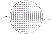
As shown in fig. 1, 9 and 10, in order to reduce noise, a muffler plate 71 is transversely provided in the premixing chamber 21, and the muffler plate 71 is positioned below, preferably directly below, the burner plate a so that flames are relatively uniform, and a space between the muffler plate 71 and the burner plate a is 3mm or 5mm.
The muffler plate 71 is provided with a plurality of muffler holes 711 penetrating through the wall thickness, the muffler holes 711 can play roles of converting current and interfering combustion frequency, the sizes of the muffler holes 711 on the muffler plate 71 can be the same or different, and the muffler holes 711 can be vertically arranged or obliquely arranged.
If the number of through holes (including the first through holes 11 and the second through holes 12) on the furnace plate is larger, only one silencing plate 71 can be arranged, at least two silencing plates 71 are arranged at intervals from top to bottom in sequence when the number of through holes on the furnace plate is smaller and the combustion power is larger, the distance between every two adjacent silencing plates 71 is larger than the wall thickness of each silencing plate 71, so that no resistance is generated in the silencing holes 711 and between every two adjacent silencing plates 71, and the silencing holes 711 on the two adjacent silencing plates 71 can be staggered and can be vertically and correspondingly arranged.
The lower part of the muffler plate 71 is also provided with a burn-in plate 72, the burn-in plate 72 is provided with a plurality of third through holes 721, and the third through holes 721 form a hole array which is actually debugged and fixed according to the power of the burner, the size of the furnace plate, the size of the fan and other factors.
Example 2
As shown in fig. 11, in the present embodiment, the structure of the fourth slat 162 is different from that of embodiment 1, and other references are made to embodiment 1.
The fourth strip 162 includes a plurality of plates 1622 disposed in sequence in the left-right direction, each plate 1622 being inclined toward the wall 16221 of the adjacent plate 1622 from top to bottom toward the other, so that a gap 1623 having a tapered longitudinal section is formed between the adjacent two plates 1622, i.e., the second through hole 12 formed in this embodiment is a through hole having a large upper portion and a small lower portion, so that the flow rate of the combustion gas (mixed gas and air) can be reduced, and the combustion stability can be improved. The longitudinal section of the gap 1623 is not limited to a tapered shape, and may be a stepped hole with a gradually smaller diameter from top to bottom, and each hole of the stepped hole may be a rectangular hole or a trapezoidal hole with a larger upper portion and a smaller lower portion.
Example 3
As shown in fig. 12 and 13, in this embodiment, the structure of the furnace plate a is different from that of embodiment 1, and other references are made to embodiment 1.
In this embodiment, the panel 1 is a monolithic plate, and the material of the panel 1 may be metal, ceramic or powder alloy, and the ceramic material and the powder alloy material have poor heat conductivity, so that the panel can be manufactured into a monolithic plate, but the ceramic material has poor mechanical strength and is easy to break, weather, peel off, and the like; the powder alloy material has the same defects as the ceramic plate when the metal content is high, the property is close to that of the metal plate when the metal content is low, but the cost is low.
The panel 1 is provided with a plurality of first jacks 14 and a plurality of second jacks 13, each first jack 14 is inserted with a hollow columnar body 141, the hollow part of the columnar body 141 forms a second through hole 12, the upper end surface of the columnar body 141 is higher than the upper end surface of the panel 1, and the part of the columnar body 141 exposed out of the first jack 14 forms a boss.
Each of the second insertion holes 13 is inserted with a hollow bar 131, and the hollow portion of the bar 131 forms a first through hole 11, and the upper end surface of the bar 131 is higher than the upper end surface of the panel 1 and lower than the upper end surface of the boss. The first through hole 11 may be directly formed on the panel 1, that is, the second insertion hole 13 may be used as a first through hole, without inserting the bar 131 therein, and the first through hole 11 in this embodiment may be formed in a manner that the bar 131 is directly removed for replacement after the first through hole 11 is blocked; the first through hole 11 burns and heats the hollow cylindrical body 141, so that the burner enters a high Wen Chuanlian combustion state, and the purpose of improving the heat efficiency is achieved.
The apertures of the first and second insertion holes can be made to be the same, the requirements of the first and second through holes can be met by the size of the openings of the strip-shaped body and the columnar body, and the first insertion hole 14 and the second insertion hole 13 with different apertures, namely, large insertion holes and small insertion holes can be formed as shown in fig. 13.
The integral structure of the panel 1 is convenient to process and manufacture, but the design mode of a whole plate is that the panel 1 has low initial heating speed, is easy to generate flame separation phenomenon, and has low subsequent cooling speed of the panel 1.
In the description and claims of the present utility model, directional terms such as "front", "rear", "upper", "lower", "left", "right", "side", "top", "bottom", etc. are used to describe various example structural parts and elements of the present utility model, but these terms are used herein for convenience of description only and are determined based on the example orientations shown in the drawings, so these directional terms are used by way of illustration only and should not be construed as limiting.
Claims (8)
1. The utility model provides a stove plate for on combustor, includes panel (1), be equipped with the boss on panel (1), the up end of boss is higher than the up end of panel (1), a plurality of first through-holes (11) that vertically link up have been seted up on panel (1), just still set up on panel (1) and link up its wall thickness and second through-hole (12) of boss, each all be equipped with aforementioned first through-hole (11) around second through-hole (12), its characterized in that: the area of each second through hole (12) is larger than that of each first through hole (11); the area of each second through hole (12) is denoted as A, and the area of each first through hole (11) is denoted as B, A >1.5B.
2. The furnace plate of claim 1, wherein: a is that<51 mm 2 。
3. The furnace plate of claim 1, wherein: the second through hole (12) is a through hole with a large upper part and a small lower part.
4. The furnace plate of claim 1, wherein: the panel (1) is a monolithic platy body, a plurality of first jacks (14) are formed in the panel (1), hollow columnar bodies (141) are inserted into the first jacks (14), the hollow parts of the columnar bodies (141) form the second through holes (12), the upper end faces of the columnar bodies (141) are higher than the upper end faces of the panel (1), and the parts of the columnar bodies (141) exposed out of the first jacks (14) form the bosses.
5. The furnace plate of claim 4, wherein: the panel (1) is further provided with a plurality of second jacks (13), each second jack (13) is internally provided with a hollow strip body (131) in an inserted mode, the hollow part of each strip body (131) forms the first through hole (11), and the upper end face of each strip body (131) is higher than the upper end face of the panel (1) and lower than the upper end face of the boss.
6. The furnace plate of claim 1, wherein: the panel (1) is a metal plate, the panel (1) comprises a first plate body (15) and a second plate body (16) which are sequentially and alternately overlapped in the front-back direction, the first through hole (11) is formed in the first plate body (15), and the second through hole (12) is formed in the second plate body (16).
7. The furnace plate of claim 6, wherein: the first plate body (15) further comprises a first plate strip (151) and a second plate strip (152) which are overlapped in the front-back direction, an air inlet groove (1511) is formed in the bottom of the first plate strip (151), an air outlet groove (1521) is formed in the top of the second plate strip (152), and the air inlet groove (1511) and the air outlet groove (1521) at least partially correspond to each other in the front-back direction under the overlapped state of the first plate strip (151) and the second plate strip (152) so as to form the first through hole (11).
8. The burner plate of claim 7, wherein: the second plate body (16) further comprises a third plate strip (161), a fourth plate strip (162) and a fifth plate strip (163) which are overlapped in the front-back direction, the fourth plate strip (162) comprises a plurality of plates (1622) which are sequentially arranged in the left-right direction, gaps (1623) are formed between every two adjacent plates (1622), the second through holes (12) are formed by surrounding the adjacent two plates (1622) and the third plate strip (161) and the fifth plate strip (163) together, and the parts, exposed out of the upper surface of the panel (1), of the third plate strip (161), the fourth plate strip (162) and the fifth plate strip (163) after surrounding the second through holes (12) are the bosses.
Priority Applications (1)
| Application Number | Priority Date | Filing Date | Title |
|---|---|---|---|
| CN202110670441.2A CN113357630B (en) | 2021-06-17 | 2021-06-17 | Furnace plate for burner |
Applications Claiming Priority (1)
| Application Number | Priority Date | Filing Date | Title |
|---|---|---|---|
| CN202110670441.2A CN113357630B (en) | 2021-06-17 | 2021-06-17 | Furnace plate for burner |
Publications (2)
| Publication Number | Publication Date |
|---|---|
| CN113357630A CN113357630A (en) | 2021-09-07 |
| CN113357630B true CN113357630B (en) | 2023-05-23 |
Family
ID=77534731
Family Applications (1)
| Application Number | Title | Priority Date | Filing Date |
|---|---|---|---|
| CN202110670441.2A Active CN113357630B (en) | 2021-06-17 | 2021-06-17 | Furnace plate for burner |
Country Status (1)
| Country | Link |
|---|---|
| CN (1) | CN113357630B (en) |
Citations (14)
| Publication number | Priority date | Publication date | Assignee | Title |
|---|---|---|---|---|
| CN2087734U (en) * | 1991-04-18 | 1991-10-30 | 胡贵友 | Flame and infrared radiation mixed gas-firing device |
| JPH05302705A (en) * | 1992-04-24 | 1993-11-16 | Noritz Corp | Premixed combustion apparatus |
| DE19955449A1 (en) * | 1999-11-17 | 2001-05-23 | Agt Gas Technology Gmbh | Gas burner for hob of gas cooker; has nozzle holder under cooker surface to supply gas to upper nozzle, vertical channel to mix gas and air and burner cover with outer groove forming gas chamber |
| JP2003035403A (en) * | 2001-05-17 | 2003-02-07 | Narita Seitoushiyo:Kk | Combustion plate and infrared burner |
| CN1603684A (en) * | 2004-10-29 | 2005-04-06 | 王予意 | Sheet string type fire tier for gas combustor |
| JP2006349311A (en) * | 2005-06-20 | 2006-12-28 | Yamatake Corp | Gas burner |
| CN201391869Y (en) * | 2008-12-17 | 2010-01-27 | 李宗仁 | High-efficiency and energy-saving infrared combustion board for gas furnace |
| CN102966951A (en) * | 2011-08-31 | 2013-03-13 | 布里福运动公司 | Systems and methods for integrating a logo on an infrared burner |
| CN103267287A (en) * | 2013-05-28 | 2013-08-28 | 徐建波 | High-efficiency burner of blast type gas cooking appliance |
| CN203413637U (en) * | 2013-07-24 | 2014-01-29 | 青岛瑞迪燃气具制造有限公司 | Metal infrared combustion plate and combustor with combustion plate |
| CN104048296A (en) * | 2014-06-27 | 2014-09-17 | 艾欧史密斯(中国)热水器有限公司 | Fuel gas pre-mixing burner |
| CN104595897A (en) * | 2014-12-03 | 2015-05-06 | 武汉科技大学 | Single-layer porous foam ceramic plate partial pre-mixing fuel gas combustor |
| EP3012526A1 (en) * | 2014-10-24 | 2016-04-27 | Rinnai Corporation | Combustion plate |
| CN208967795U (en) * | 2018-10-12 | 2019-06-11 | 温岭市亿源燃气设备有限公司 | A kind of tray for combustion for gas infrared burner |
-
2021
- 2021-06-17 CN CN202110670441.2A patent/CN113357630B/en active Active
Patent Citations (14)
| Publication number | Priority date | Publication date | Assignee | Title |
|---|---|---|---|---|
| CN2087734U (en) * | 1991-04-18 | 1991-10-30 | 胡贵友 | Flame and infrared radiation mixed gas-firing device |
| JPH05302705A (en) * | 1992-04-24 | 1993-11-16 | Noritz Corp | Premixed combustion apparatus |
| DE19955449A1 (en) * | 1999-11-17 | 2001-05-23 | Agt Gas Technology Gmbh | Gas burner for hob of gas cooker; has nozzle holder under cooker surface to supply gas to upper nozzle, vertical channel to mix gas and air and burner cover with outer groove forming gas chamber |
| JP2003035403A (en) * | 2001-05-17 | 2003-02-07 | Narita Seitoushiyo:Kk | Combustion plate and infrared burner |
| CN1603684A (en) * | 2004-10-29 | 2005-04-06 | 王予意 | Sheet string type fire tier for gas combustor |
| JP2006349311A (en) * | 2005-06-20 | 2006-12-28 | Yamatake Corp | Gas burner |
| CN201391869Y (en) * | 2008-12-17 | 2010-01-27 | 李宗仁 | High-efficiency and energy-saving infrared combustion board for gas furnace |
| CN102966951A (en) * | 2011-08-31 | 2013-03-13 | 布里福运动公司 | Systems and methods for integrating a logo on an infrared burner |
| CN103267287A (en) * | 2013-05-28 | 2013-08-28 | 徐建波 | High-efficiency burner of blast type gas cooking appliance |
| CN203413637U (en) * | 2013-07-24 | 2014-01-29 | 青岛瑞迪燃气具制造有限公司 | Metal infrared combustion plate and combustor with combustion plate |
| CN104048296A (en) * | 2014-06-27 | 2014-09-17 | 艾欧史密斯(中国)热水器有限公司 | Fuel gas pre-mixing burner |
| EP3012526A1 (en) * | 2014-10-24 | 2016-04-27 | Rinnai Corporation | Combustion plate |
| CN104595897A (en) * | 2014-12-03 | 2015-05-06 | 武汉科技大学 | Single-layer porous foam ceramic plate partial pre-mixing fuel gas combustor |
| CN208967795U (en) * | 2018-10-12 | 2019-06-11 | 温岭市亿源燃气设备有限公司 | A kind of tray for combustion for gas infrared burner |
Also Published As
| Publication number | Publication date |
|---|---|
| CN113357630A (en) | 2021-09-07 |
Similar Documents
| Publication | Publication Date | Title |
|---|---|---|
| US4569328A (en) | Efficient, low emissions gas range cooktop | |
| EP2348934B1 (en) | Parallel tube burner with improved cooling and reduced size | |
| JP3814604B2 (en) | Gas combustion burner realizing multi-stage control | |
| WO2016074582A1 (en) | Gas premix burner and gas water heater | |
| CN107420897B (en) | Combustor and gas stove | |
| CN201377835Y (en) | A gas stove outer ring fire cover | |
| JP3814603B2 (en) | Premixed gas combustion burner with separated flame holes | |
| KR20040040577A (en) | premix type knitted metal fiber mat gas burner | |
| CN109695873B (en) | Flow equalization fire piece | |
| CN208779447U (en) | A kind of new and effective fuel wall hanging burner | |
| CN113357630B (en) | Furnace plate for burner | |
| CN213577479U (en) | A combustion component and burner | |
| CN113357629B (en) | Burner | |
| CN212566321U (en) | Combustor and gas water heater using same | |
| CN210050802U (en) | Combustor and gas heater | |
| CN217540734U (en) | Complete premix combustor and water heater | |
| CN210004383U (en) | Burner and oven | |
| CN112066369B (en) | Combustor, hanging stove and water heater | |
| CN204739583U (en) | stove burner | |
| CN108954311A (en) | A kind of variable orifice diameter porous ceramic plate | |
| CN211316571U (en) | Fire grate unit, combustor and water heater | |
| CN210801380U (en) | Ventilation baffle and wall-mounted boiler | |
| CN218763387U (en) | Full-premixing two-section type medium combustion device | |
| CN112665185A (en) | Fire grate unit, combustor and water heater | |
| CN220442509U (en) | Cooking unit with high temperature zone |
Legal Events
| Date | Code | Title | Description |
|---|---|---|---|
| PB01 | Publication | ||
| PB01 | Publication | ||
| SE01 | Entry into force of request for substantive examination | ||
| SE01 | Entry into force of request for substantive examination | ||
| GR01 | Patent grant | ||
| GR01 | Patent grant |