CN113353802B - Device and method for automatically judging degradation of crown block wheel and track - Google Patents
Device and method for automatically judging degradation of crown block wheel and track Download PDFInfo
- Publication number
- CN113353802B CN113353802B CN202110534598.2A CN202110534598A CN113353802B CN 113353802 B CN113353802 B CN 113353802B CN 202110534598 A CN202110534598 A CN 202110534598A CN 113353802 B CN113353802 B CN 113353802B
- Authority
- CN
- China
- Prior art keywords
- crown block
- speed
- overhead traveling
- traveling crane
- track
- Prior art date
- Legal status (The legal status is an assumption and is not a legal conclusion. Google has not performed a legal analysis and makes no representation as to the accuracy of the status listed.)
- Active
Links
Images


Classifications
-
- B—PERFORMING OPERATIONS; TRANSPORTING
- B66—HOISTING; LIFTING; HAULING
- B66C—CRANES; LOAD-ENGAGING ELEMENTS OR DEVICES FOR CRANES, CAPSTANS, WINCHES, OR TACKLES
- B66C13/00—Other constructional features or details
- B66C13/16—Applications of indicating, registering, or weighing devices
-
- B—PERFORMING OPERATIONS; TRANSPORTING
- B66—HOISTING; LIFTING; HAULING
- B66C—CRANES; LOAD-ENGAGING ELEMENTS OR DEVICES FOR CRANES, CAPSTANS, WINCHES, OR TACKLES
- B66C15/00—Safety gear
-
- B—PERFORMING OPERATIONS; TRANSPORTING
- B66—HOISTING; LIFTING; HAULING
- B66C—CRANES; LOAD-ENGAGING ELEMENTS OR DEVICES FOR CRANES, CAPSTANS, WINCHES, OR TACKLES
- B66C15/00—Safety gear
- B66C15/06—Arrangements or use of warning devices
-
- G—PHYSICS
- G01—MEASURING; TESTING
- G01M—TESTING STATIC OR DYNAMIC BALANCE OF MACHINES OR STRUCTURES; TESTING OF STRUCTURES OR APPARATUS, NOT OTHERWISE PROVIDED FOR
- G01M13/00—Testing of machine parts
-
- G—PHYSICS
- G01—MEASURING; TESTING
- G01M—TESTING STATIC OR DYNAMIC BALANCE OF MACHINES OR STRUCTURES; TESTING OF STRUCTURES OR APPARATUS, NOT OTHERWISE PROVIDED FOR
- G01M13/00—Testing of machine parts
- G01M13/04—Bearings
- G01M13/045—Acoustic or vibration analysis
Abstract
The invention relates to a device and a method for automatically judging degradation of wheels and rails of a crown block, belonging to the technical field of steelmaking automation. The technical scheme of the invention is as follows: the vibration transmitter (4) of the wheel bearing box of the crown block is arranged on the corner box of the wheel bearing of the crown block (1), and the output signal is connected to the signal high-speed collector (5); the input ends of a main lifting weight collector (6), a crown block walking position detector (7) and a crown block walking first-gear operation signal collector (8) are respectively connected with a crown block (1), and the output end is connected with a signal high-speed collector (5); the signal high-speed collector (5) is connected with the track deterioration system analysis and judgment software (9). The invention has the advantages that the vibration condition of the wheels in online operation is monitored in real time, the wheel bearing degradation vibration value and the degradation value of the rail joint are obtained quantitatively, the occurrence of crown block accidents is effectively avoided, and favorable help is provided for the good operation of crown blocks.
Description
Technical Field
The invention relates to a device and a method for automatically judging degradation of wheels and rails of a crown block, belonging to the field of automation of steel making.
Background
The steel-making of stainless steel company has 55 crown blocks which are distributed at different positions such as a knockout span, a molten steel span, a feeding span, a slag span and the like, the lifting tonnage is different from 10W to 240W, the service life of the crown blocks is longer, parts of equipment are aged, and the hidden troubles such as bearing necrosis, wheel gnawing and the like frequently occur in the operation process. When the equipment maintenance personnel check, the sound identification is usually carried out by using a sound listening rod, the operation process is dangerous, and quantification cannot be carried out in the checking process. With the severe safety situation, guard rails are arranged on the running periphery of the overhead travelling crane, and the spot inspection personnel cannot operate by using the listening rods.
Disclosure of Invention
The invention aims to provide a device and a method for automatically judging the degradation of wheels and tracks of a crown block.A vibration transmitter is arranged on a corner box of a wheel bearing of the crown block, so that the vibration condition of the wheels in online operation is monitored in real time, the collected signals are subjected to logic analysis, the degradation vibration value of the wheel bearing, the degradation value of a track joint and the track gnawing degree value of the wheels are obtained quantitatively, the three measured values are compared with a preset standard value to output an overproof judgment result, each measured value can be combined with the previous measured value to form a change trend graph, corresponding reference data are provided for equipment maintenance, the occurrence of crown block accidents is effectively avoided, favorable help is provided for the good operation of the crown block, and the problems in the background technology are effectively solved.
The technical scheme of the invention is as follows: a device for automatically judging degradation of wheels and rails of an overhead traveling crane comprises an overhead traveling crane, an overhead traveling crane rail, a rail joint, an overhead traveling crane wheel bearing box vibration transmitter, a signal high-speed collector, a main lifting weight collector, an overhead traveling crane walking position detector, an overhead traveling crane walking first-gear operation signal collector and overhead traveling crane wheel and rail degradation system analysis and judgment software, wherein the overhead traveling crane wheel bearing box vibration transmitter is arranged on a corner box of an overhead traveling crane wheel bearing, and an output signal is connected to the signal high-speed collector; the input ends of the main hoisting weight collector, the crown block walking position detector and the crown block walking first-gear operation signal collector are respectively connected with the crown block, and the output end of the main hoisting weight collector and the crown block walking first-gear operation signal collector is connected with the signal high-speed collector; and the signal high-speed collector is connected with the track degradation system analysis and judgment software.
The vibration acquisition frequency of the crown block wheel bearing box vibration transmitter is 1000 HZ.
The main lifting weight collector comprises a weight sensor and a secondary measuring instrument, the weight sensor is supported by a fixed pulley bearing seat of a main lifting system of the overhead travelling crane, and an output weight signal is 0-1V; the overhead traveling crane walking position detector comprises a coding cable and a position detector, the coding cable is laid outside an overhead traveling crane track, the position detector is installed at an end beam of the overhead traveling crane, and an output position signal is 0-1V; the overhead traveling crane walking first-gear operation signal collector comprises an operation contactor, an auxiliary contact and an output switching value signal.
The signal high-speed collector is a USB DAQ-580I type, the nonlinearity of the signal high-speed collector is +/-0.00030% FSR, four channels are adopted, and the sampling speed is as follows: 2.5sps-30 ksps.
The analysis and judgment software of the crown block wheel and track degradation system is pyWhon language programming software and comprises a model selection module, a wheel bearing model, a track joint model, a wheel gnawing model and an alarm recording module.
A method for automatically judging degradation of crown block wheels and rails comprises the following steps:
and S1, setting the crown block to run at a constant speed: the crown block worker operates the crown block and uses the crown block to enter a constant-speed running state;
s2-1: auxiliary signal acquisition-overhead traveling crane operating position: a coding cable is laid on the outer side of the track, an overhead traveling crane walking position detector is mounted at an end beam of the overhead traveling crane, and when the overhead traveling crane runs to a certain position, the overhead traveling crane walking position detector identifies Gray codes on the cable, so that the specific position of the overhead traveling crane can be accurately read;
s2-2: auxiliary signal acquisition-acquisition of hoisting tonnage: a weight sensor is arranged at the supporting position of a fixed pulley bearing seat of the main hoisting system, and the weight of a hoisted heavy object is displayed through a secondary measuring instrument;
s2-3: auxiliary signal acquisition-acquisition of the running speed of the crown block: the method comprises the following steps that when a crown block is in a constant-speed running state, a crown block walks by a first-gear running signal collector to collect running signals;
s3-1: selecting a bearing degradation model, wherein in the running process of the crown block, a running signal is 1, which indicates that the running condition of the crown block is met, presetting a smooth track position range without joints and a rail gnawing condition, when the crown block enters the starting point of the smooth track position range, the main lifting and hoisting tonnage is normal, meeting the condition of the bearing degradation model, and a signal high-speed collector collects a bearing vibration signal until the crown block runs to the end point of the smooth track position range;
s3-2: analyzing a bearing degradation model, namely selecting wheels of a cart working for about 1 year, driving a crown block from a starting point to an end point of a position range of a smooth track, enabling the main lifting tonnage to be normal, enabling the running speed of the crown block to be uniform, simultaneously keeping a trolley and lifting to be in a stop action state, transmitting vibration signals collected by a high-speed signal collector to a computer, and analyzing and judging software by a system for analyzing the wheels of the cart and the track degradation to form a wheel bearing vibration model; secondly, selecting wheels of a large vehicle working for about 5 years, driving the crown block from a starting point to an end point of a position range of a smooth track, enabling the main lifting tonnage to be normal, enabling the crown block to run at a constant speed, simultaneously keeping the trolley and lifting to be in a stop action state, transmitting the vibration signals collected by the high-speed signal collector to a computer, and forming a wheel bearing vibration aging model after analysis of analysis judgment software of the wheels of the large vehicle and the track degradation system;
s4-1: selecting a track joint vibration model, wherein the main hoisting tonnage is normal, the running speed of the overhead traveling crane is constant, and when the overhead traveling crane enters the track joint position, the signal high-speed collector starts to collect bearing vibration signals until the overhead traveling crane passes through the track joint position;
s4-2: analyzing a track joint vibration model, wherein the main lifting tonnage is normal, the running speed of a crown block is uniform, the crown block starts to collect from a position 0.5 m before entering the position of the track joint and finishes collecting after entering a smooth section about 0.5 m after passing through the track joint under the condition that a trolley and lifting are kept to stop acting, a high-speed collector transmits a collected vibration signal to a computer, and analysis and judgment software of crown block wheels and a track degradation system analyzes the data, calculates the width of the joint, and compares the measured joint distance with standard and original joint data to form a track joint degradation model;
s5-1: selecting a rail gnawing model, enabling the overhead traveling crane to run at a constant speed and enter a smooth rail with a wheel gnawing phenomenon, enabling the main lifting tonnage to be normal, enabling the overhead traveling crane to run at a constant speed, meeting the conditions of the rail gnawing model at the moment, and enabling a signal high-speed collector to start collecting bearing vibration signals until the overhead traveling crane runs through the wheel gnawing position before the overhead traveling crane enters the wheel gnawing position;
s5-2: analyzing a rail gnawing model, wherein the lifting and hoisting tonnage of a heavenly main is normal, the running speed of an overhead traveling crane is uniform, meanwhile, under the state that a trolley and lifting are kept to stop acting, the overhead traveling crane starts to collect from a position 2-3 meters before entering a rail gnawing position, enters a smooth section after passing the rail gnawing and finishes collecting after about 2-3 meters, a signal high-speed collector transmits collected vibration signals to a computer, analysis and judgment software of overhead traveling crane wheels and a rail degradation system analyzes and judges the data, the length of the gnawing rail is calculated, and the rail gnawing data is measured and compared with standard and original rail gnawing vibration data to form a wheel gnawing rail model;
and S6, according to the results of the analysis and judgment of the three models, measuring the standard exceeding alarm, and storing the data into an alarm recording module.
The invention has the beneficial effects that: the vibration transmitter is arranged on a corner box of a wheel bearing of the overhead travelling crane, so that the vibration condition of wheels in online operation is monitored in real time, the collected signals are subjected to logic analysis, the wheel bearing degradation vibration value, the rail joint degradation value and the wheel gnawing distance value are obtained in a quantification manner, the three measurement values are compared with the preset standard value to output an overproof judgment result, each measurement value can be combined with the previous measurement value to form a change trend graph, corresponding reference data is provided for equipment maintenance, the occurrence of overhead travelling crane accidents is effectively avoided, and favorable help is provided for the good operation of the overhead travelling crane.
Drawings
FIG. 1 is a schematic structural view of the present invention;
FIG. 2 is a flow chart of the present invention for automatic determination of crown block wheel and rail degradation;
FIG. 3 is a diagram of a wheel bearing vibration model according to an embodiment of the present invention;
FIG. 4 is a vibration aging model diagram of a wheel bearing according to an embodiment of the present invention;
FIG. 5 is a diagram of a model for degradation of a rail joint in accordance with an embodiment of the present invention;
FIG. 6 is a diagram of a wheel gnawing model according to an embodiment of the present invention;
in the figure: the system comprises a crown block 1, a crown block track 2, a track joint 3, a crown block wheel bearing box vibration transmitter 4, a signal high-speed collector 5, a main lifting weight collector 6, a crown block walking position detector 7, a crown block walking first-gear operation signal collector 8, crown block wheel and track degradation system analysis and judgment software 9, a model selection module 91, a wheel bearing model 92, a track joint model 93, a wheel gnawing model 94 and an alarm recording module 95.
Detailed Description
In order to make the objects, technical solutions and advantages of the embodiments of the present invention clearer, the following will clearly and completely describe the technical solutions of the embodiments of the present invention with reference to the drawings of the embodiments, and it is obvious that the described embodiments are a small part of the embodiments of the present invention, rather than all embodiments, and all other embodiments obtained by a person of ordinary skill in the art without creative work based on the embodiments of the present invention belong to the protection scope of the present invention.
A device for automatically judging degradation of wheels and rails of a crown block comprises a crown block 1, a crown block rail 2, a rail joint 3, a crown block wheel bearing box vibration transmitter 4, a signal high-speed collector 5, a main lifting weight collector 6, a crown block walking position detector 7, a crown block walking first-gear operation signal collector 8 and crown block wheel and rail degradation system analysis and judgment software 9, wherein the crown block wheel bearing box vibration transmitter 4 is arranged on a corner box of the wheel bearing of the crown block 1, and an output signal is connected to the signal high-speed collector 5; the input ends of a main hoisting weight collector 6, a crown block walking position detector 7 and a crown block walking first-gear operation signal collector 8 are respectively connected with a crown block 1, and the output end is connected with a signal high-speed collector 5; the signal high-speed collector 5 is connected with a track deterioration system analysis and judgment software 9.
The vibration acquisition frequency of the crown block wheel bearing box vibration transmitter 4 is 1000 HZ.
The main lifting weight collector 6 comprises a weight sensor and a secondary measuring instrument, the weight sensor is supported by a fixed pulley bearing seat of a main lifting system of the overhead travelling crane, and an output weight signal is 0-1V; the crown block walking position detector 7 comprises a coding cable and a position detector, the coding cable is laid outside the crown block track 2, the position detector is installed at the end beam of the crown block, and an output position signal is 0-1V; the first-gear running signal collector 8 for the travelling crane comprises a running contactor, collects an auxiliary contact and outputs a switching value signal.
The signal high-speed collector 5 is a USB DAQ-580I type, the nonlinearity of the signal high-speed collector is +/-0.00030% FSR, four channels are adopted, and the sampling speed is as follows: 2.5sps-30 ksps.
The analysis and judgment software 9 of the crown block wheel and track degradation system is pyWhon language programming software and comprises a model selection module 91, a wheel bearing model 92, a track joint model 93, a wheel gnawing model 94 and an alarm recording module 95.
A method for automatically judging degradation of crown block wheels and rails comprises the following steps:
and S1, setting the crown block to run at a constant speed: the crown block worker operates the crown block and uses the crown block to enter a constant-speed running state;
s2-1: auxiliary signal acquisition-overhead traveling crane operating position: a coding cable is laid on the outer side of the track, an overhead traveling crane walking position detector is mounted at an end beam of the overhead traveling crane, and when the overhead traveling crane runs to a certain position, the overhead traveling crane walking position detector identifies Gray codes on the cable, so that the specific position of the overhead traveling crane can be accurately read;
s2-2: auxiliary signal acquisition-acquisition of hoisting tonnage: a weight sensor is arranged at the supporting position of a fixed pulley bearing seat of the main hoisting system, and the weight of a hoisted heavy object is displayed through a secondary measuring instrument;
s2-3: auxiliary signal acquisition-acquisition of the running speed of the crown block: the method comprises the following steps that when a crown block is in a constant-speed running state, a crown block walks by a first-gear running signal collector to collect running signals;
s3-1: selecting a bearing degradation model, wherein in the running process of the crown block, a running signal is 1, which indicates that the running condition of the crown block is met, presetting a smooth track position range without joints and a rail gnawing condition, when the crown block enters the starting point of the smooth track position range, the main lifting and hoisting tonnage is normal, meeting the condition of the bearing degradation model, and a signal high-speed collector collects a bearing vibration signal until the crown block runs to the end point of the smooth track position range;
s3-2: analyzing a bearing degradation model, namely selecting wheels of a large vehicle working for about 1 year, driving a crown block from a starting point to an end point of a position range of a smooth track, enabling the main lifting tonnage to be normal, enabling the running speed of the crown block to be uniform, simultaneously keeping a small vehicle and lifting to be in a stop action state, transmitting a vibration signal acquired by a high-speed signal acquisition device to a computer, and analyzing and judging software by using a system for analyzing the wheels of the crown block and the track degradation to form a wheel bearing vibration model; secondly, selecting wheels of a large vehicle working for about 5 years, driving the crown block from a starting point to an end point of a position range of a smooth track, enabling the main lifting tonnage to be normal, enabling the crown block to run at a constant speed, simultaneously keeping the trolley and lifting to be in a stop action state, transmitting the vibration signals collected by the high-speed signal collector to a computer, and forming a wheel bearing vibration aging model after analysis of analysis judgment software of the wheels of the large vehicle and the track degradation system;
s4-1: selecting a track joint vibration model, wherein the main lifting tonnage is normal, the running speed of the overhead traveling crane is constant, and when the overhead traveling crane enters the track joint position, the signal high-speed collector starts to collect bearing vibration signals until the overhead traveling crane passes through the track joint position;
s4-2: analyzing a track joint vibration model, wherein the main lifting tonnage is normal, the running speed of a crown block is uniform, the crown block starts to collect from a position 0.5 m before entering the position of the track joint and finishes collecting after entering a smooth section about 0.5 m after passing through the track joint under the condition that a trolley and lifting are kept to stop acting, a high-speed collector transmits a collected vibration signal to a computer, and analysis and judgment software of crown block wheels and a track degradation system analyzes the data, calculates the width of the joint, and compares the measured joint distance with standard and original joint data to form a track joint degradation model;
s5-1: selecting a rail gnawing model, enabling the overhead traveling crane to run at a constant speed and enter a smooth rail with a wheel gnawing phenomenon, enabling the main lifting tonnage to be normal, enabling the overhead traveling crane to run at a constant speed, meeting the conditions of the rail gnawing model at the moment, and enabling a signal high-speed collector to start collecting bearing vibration signals until the overhead traveling crane runs through the wheel gnawing position before the overhead traveling crane enters the wheel gnawing position;
s5-2: analyzing a rail gnawing model, wherein the lifting and hoisting tonnage of a heavenly main is normal, the running speed of an overhead traveling crane is uniform, meanwhile, under the state that a trolley and lifting are kept to stop acting, the overhead traveling crane starts to collect from a position 2-3 meters before entering a rail gnawing position, enters a smooth section after passing the rail gnawing and finishes collecting after about 2-3 meters, a signal high-speed collector transmits collected vibration signals to a computer, analysis and judgment software of overhead traveling crane wheels and a rail degradation system analyzes and judges the data, the length of the gnawing rail is calculated, and the rail gnawing data is measured and compared with standard and original rail gnawing vibration data to form a wheel gnawing rail model;
and S6, according to the results of the analysis and judgment of the three models, measuring the standard exceeding alarm, and storing the data into an alarm recording module.
In practical application, the vibration transmitter of the bearing box of the crown block wheel is arranged on the bearing angle box of the crown block wheel and is used for acquiring the vibration speed of the wheel and the vibration acquisition frequency of 1000HZ in the running process of the wheel. The system comprises a main lifting weight collector, a crown block walking position detector and a crown block walking first-gear running signal collector, which are used for collecting auxiliary signals, and is used for collecting signals such as crown block lifting tonnage, crown block running position and crown block running speed, crown block wheel and track deterioration system analysis and judgment software receives four signals of crown block wheel bearing box vibration speed, main lifting weight, crown block walking position and crown block walking first-gear running speed through the signal high-speed collector, the signals are transmitted into a computer through a USB port of the signal high-speed collector, the data are logically analyzed and calculated through the computer software, a corresponding wheel bearing model, a track joint model or a wheel gnawing model are selected after comprehensive judgment, and a wheel bearing deterioration vibration value, a track joint deterioration value and a wheel gnawing distance value are obtained through quantification. The three measurement values are compared with a preset standard value to output an overproof judgment result, each measurement value can be combined with the previous measurement value to form a change trend graph, corresponding reference data are provided for equipment maintenance, the occurrence of crown block accidents is effectively avoided, and favorable help is provided for the good running of crown blocks.
The automatic determination process of the degradation of the wheels and the rails of the crown block is as follows:
and S1, setting the crown block to run at a constant speed: and operating the crown block by the crown block worker, and enabling the crown block worker to enter a constant-speed running state, wherein if the running speed of the large vehicle is selected as the first gear, the large vehicle runs at a constant speed of 0.4 m/s.
S2-1: auxiliary signal acquisition-overhead traveling crane operating position: the overhead traveling crane walking position detector is responsible for collecting, and the coding cable location that the overhead traveling crane location of steelmaking adopted, the accurate location of 5mm can be realized to the highest precision, lays a coding cable in the track outside, and overhead traveling crane end beam department installation position detector when the overhead traveling crane moves a certain position, and Gray code on the position detector discernment cable can accurately read the concrete position X of overhead traveling crane.
S2-2: auxiliary signal acquisition-acquisition of hoisting tonnage: the weight of the lifted heavy object is displayed through a secondary measuring instrument, and the weight of the preset heavy object is between W1 and W2, so that the test condition is met.
S2-3: auxiliary signal acquisition-acquisition of the running speed of the crown block: the running signals are collected by a running signal collector when the crown block runs at a first gear, and the running signals V are collected when the crown block is in a constant-speed running state, wherein the constant-speed running condition is met within 0.39m/s to 0.41 m/s.
S3-1: selecting a bearing degradation model, wherein in the running process of the crown block, a running signal V is 1, which indicates that the running condition of the crown block is met, the position range of a smooth track (without joints and without rail gnawing) is preset to be X1 to X2, when the crown block enters the position X1 of the straight track, the main lifting tonnage is W (W1 < W < W2), the condition of the bearing degradation model is met at the moment, and a high-speed collector starts to collect bearing vibration signals until the crown block runs to the position X2 of the track.
S3-2: the bearing degradation model analysis comprises the steps of firstly selecting cart wheels of a cart working for about 1 year, enabling the cart to run from a track X1 position to an X2 position, enabling the main lifting tonnage to be W (W1 is more than W and less than W2), enabling the running speed of the cart to be V at a constant speed (V is more than 0.39m/s and less than 0.41m/s), simultaneously keeping the cart and lifting to be kept in a stop action state, transmitting vibration signals collected by a high-speed collector to a computer, and forming a wheel bearing vibration model after analysis of analysis judgment software of the cart wheels and the track degradation system.
And secondly, selecting cart wheels of a cart working for about 5 years, driving the overhead traveling crane to an X2 position from an X1 position of a track, enabling the main lifting tonnage to be W (W1 is more than W and less than W2), enabling the running speed of the overhead traveling crane to be V (0.39m/s is less than V and less than 0.41m/s), simultaneously keeping the trolley and lifting to keep stopping, transmitting the collected vibration signals to a computer by a high-speed collector, and forming a wheel bearing vibration aging model after analysis and judgment software analysis of the cart wheels and the track deterioration system.
S4-1: the method comprises the following steps that a track joint vibration model is selected, a crown block runs under the condition of constant speed, a track joint is arranged in a position from X3 to X4 of a track (without gnawing the track), when the crown block enters the position of X3 of the track, the main hoisting tonnage is W (W1 < W < W2), the running speed of the crown block is V (0.39m/s < V <0.41m/s), the condition of the track joint vibration model is met at the moment, and a high-speed collector starts to collect bearing vibration signals until the crown block runs to the position of X4 of the track.
S4-2: the rail joint vibration model analysis, the overhead traveling crane is at the uniform velocity and is gone, main lifting handling tonnage is W (W1 < W < W2), overhead traveling crane functioning speed V (0.39m/s < V <0.41m/s), keep dolly and lifting simultaneously and keep under the stop motion state, overhead traveling crane begins to gather from the position 0.5 meter before entering the rail joint position, it finishes gathering after about 0.5 meter to get into the smooth section behind the joint, high-speed collector will gather vibration signal transmission to the computer, overhead traveling crane wheel and rail degradation system analysis judge software go on the analysis to above data:
when the average vibration value A (mm/s) (FIG. 1.125 mm/s below) exceeds A0=0.536 (mm/s)
And (3) taking values of time T1 and time T2 at two ends under the trend of the interface model, and multiplying the running speed V =0.4 (m/s) of the crown block by delta T to calculate the joint spacing:
ΔT1= T2-T1=0.55-0.45=0.1(s)
ΔX1=ΔT1×V=0.1(s)×0.4(m/s)=0.04mm
and (4) calculating the joint width to be 0.04mm, and comparing the measured joint distance with standard and original joint data to form a track joint degradation model.
S5-1: the rail gnawing model is selected, the crown block runs under the condition of constant speed and enters a smooth rail (without a joint) from X5 to X6, a wheel gnawing phenomenon exists in the rail, when the crown block enters the position of X1 of the rail, the main lifting and hoisting tonnage is W (W1 < W < W2), the running speed of the crown block is V (0.39m/s < V <0.41m/s), the condition of the rail gnawing model is met at the moment, and the high-speed collector starts to collect bearing vibration signals until the crown block runs to the position of X6 of the rail.
S5-2: analyzing a rail gnawing model, wherein an overhead traveling crane runs at a constant speed, the main lifting tonnage is W (W1 < W < W2), the running speed of the overhead traveling crane is V (0.39m/s < V <0.41m/s), meanwhile, the overhead traveling crane and the lifting are kept in a stop action state, the overhead traveling crane starts to collect 2-3 meters before entering a rail gnawing position, the collection is finished after entering a smooth section for about 2-3 meters after passing the gnawing, a high-speed collector transmits collected vibration signals to a computer, and analysis and judgment software of an overhead traveling crane wheel and a rail degradation system analyzes the data:
when the vibration value a (mm/s) (the lower graph 2.778 mm/s) exceeds a0=0.536 (mm/s), the values of the two-end time T3 and T4 are taken under the trend of the rail gnawing model, and the rail gnawing distance is calculated by multiplying the running speed V =0.4 (m/s) of the crown block by Δ T2:
ΔT2= T4-T3=11.5-3.8=7.7(s)
ΔX2=ΔT2×V=7.7(s)×0.4(m/s)=3.08m
and calculating the length of the rail gnawing result to be 3.08m, and comparing the measured rail gnawing data with standard and original rail gnawing vibration data to form a wheel rail gnawing model.
And S6, according to the results of the analysis and judgment of the three models, measuring the standard exceeding alarm, and storing the data into an alarm recording module.
Example (b):
the type of the vibration transmitter is CYQ-9250-5-S1-C-L3, and the sensitivity of the equipment is 50 mV/mm/S/+/-5%; the frequency response is 5-1000Hz, and the measuring range is 0-200 um. The device is arranged on a bearing angle box of a crown block wheel and is used for collecting the vibration speed of the wheel in the running process of the wheel.
The main lifting weight collector, the crown block walking position detector and the crown block walking one-gear running signal collector are used for collecting auxiliary signals and are used for collecting signals of crown block lifting tonnage, crown block running position, crown block running speed and the like.
The specific parameters of the high-speed collector are USB DAQ-580I24 bit AD data acquisition equipment, and the nonlinearity is +/-0.00030% FSR; four channels; voltage measurement range: 1.25V; sampling speed: 2.5sps-30ksps, USB2.0 full speed. The high-speed collector collects four signals of a vibration signal of a wheel bearing box of the crown block, a main lifting weight signal, a crown block walking position signal and a crown block walking one-gear running speed, and transmits the signals to crown block wheels and track deterioration system analysis and judgment software.
The analysis and judgment software of the crown block wheel and track deterioration system adopts Python language programming software, four signals collected by a crown block wheel bearing box vibration transmitter, a main lifting weight collector, a crown block walking position detector and a crown block walking one-gear operation signal collector are received by a signal high-speed collector and are transmitted into a computer through a USB port of the high-speed collector, the data are subjected to logic analysis and calculation by the computer software, and a corresponding wheel bearing model, a track joint model and a wheel gnawing rail model are selected after comprehensive judgment, so that a wheel bearing deterioration vibration value, a track joint deterioration value and a wheel gnawing rail distance value are obtained in a quantized mode. The three measurement values are compared with a preset standard value to output an overproof judgment result, and each measurement value can be combined with the previous measurement value to form a change trend graph so as to provide corresponding reference data for equipment maintenance.
The main process is as follows:
and S1, setting the crown block to run at a constant speed: the crown block worker operates the crown block, the crown block is used for entering a constant speed operation state, the operation speed of the crown block is selected as the first gear in the implementation case, the crown block runs at a constant speed of 0.4m/s, and the crown block lifts 160 tons of ladles.
S2-1: auxiliary signal acquisition-overhead traveling crane operating position: the overhead traveling crane in the right is responsible for collection, the coding cable used for positioning the steel-making overhead traveling crane is positioned, the highest precision can realize the precise positioning of 5mm, one coding cable is laid on the outer side of a track, the position detector is arranged at the end beam of the overhead traveling crane, and when the overhead traveling crane runs to a certain position, the position detector identifies the Gray code on the cable, so that the specific position X of the overhead traveling crane can be accurately read.
S2-2: auxiliary signal acquisition-acquisition of hoisting tonnage: the method is characterized in that the hoisting tonnage is collected by a main hoisting weight collector in the claim, a weight sensor is arranged at the supporting position of a fixed pulley bearing seat of a main hoisting system, and the weight of a hoisted heavy object is displayed by a secondary measuring instrument to be 160W.
S2-3: and thirdly, collecting the running speed of the crown block, wherein the running speed of the crown block can be collected by a running first-gear running signal collector in the right, and the running speed V =0.4m/s of the crown block can be collected by controlling a switch signal by a running contactor when the crown block is in a constant-speed running state.
S3-1: selecting a bearing degradation model, wherein the crown block runs at a constant speed and enters a smooth track (without interfaces and rail gnawing conditions) from X1=100 m to X2=120 m, the main lifting tonnage is 160W when the crown block enters a straight track X1 position, the running speed of the crown block is 0.4m/s, the condition of the bearing degradation model is met at the moment, and the high-speed collector starts to collect bearing vibration signals until the crown block runs to the track X2 position.
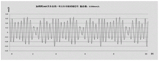
S3-2: the bearing degradation model analysis comprises the steps of firstly selecting cart wheels of a cart working for about 1 year, wherein the bearing models are 22334CC/W33 and 170X 360X 120, the crown block runs to an X2 position from an X1 position of a rail, the tonnage of a main lifting crane is 160W, the running speed of the crown block is 0.4m/s, meanwhile, under the condition that the cart and the lifting crane are kept to stop acting, a high-speed collector transmits collected vibration signals to a computer, and after analysis and judgment software analysis of the cart wheels and the rail degradation system, the vibration value of a wheel bearing is 0.536mm/s, as shown in figure 3.
And secondly, selecting cart wheels of a cart working for about 5 years, wherein the bearing models are 22334CC/W33 and 170X 360X 120, the crown block runs to an X2 position from an X1 position of a track, the main lifting tonnage is 160W, the running speed of the crown block is 0.4m/s, simultaneously keeping the cart and the lifting to be in a stop action state, transmitting the collected vibration signals to a computer by a high-speed collector, and obtaining the aging vibration value of the wheel bearing of 1.778mm/s after analysis of analysis judgment software of the cart wheels and the track degradation system, as shown in figure 4.
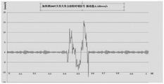
S4-1: the method comprises the following steps that a rail joint vibration model is selected, a crown block runs under the condition of constant speed, the crown block enters a smooth rail (without gnawing rail) X3=140 m to X4=141 m, a joint is arranged in the section of the rail, when the crown block enters the position of a rail X3, the main lifting tonnage is 160W, the running speed of the crown block is 0.4m/s, the condition of the rail joint vibration model is met, and a high-speed collector starts to collect bearing vibration signals until the crown block runs to the position of the rail X4.
S4-2: the method comprises the following steps of analyzing a track joint vibration model, enabling a crown block to run at a constant speed, enabling the tonnage of main lifting to be 160W, enabling the running speed of the crown block to be 0.4m/s, simultaneously keeping a trolley and lifting to be kept in a stop motion state, starting to collect the crown block from a position 0.5 m before the crown block enters a track joint position, finishing collection after the crown block enters a smooth section after passing the joint and being about 0.5 m, transmitting vibration signals to a computer by a high-speed collector, and analyzing and judging the data by using analysis and judgment software of crown block wheels and a track degradation system:
when the average value of the vibration value A (mm/s) (fig. 1.125 mm/s below) exceeds A0=0.536 (mm/s) and is in the interface model trend, the values of the two end time T1 and T2 are taken, and the running speed V =0.4 (m/s) of the crown block is multiplied by delta T1 to calculate the joint spacing:
ΔT1= T2-T1=0.55-0.45=0.1(s)
ΔX1=ΔT1×V=0.1(s)×0.4(m/s)=0.04mm
the calculated joint width was 0.04mm and a model of rail joint degradation was generated by comparing the measured joint distance with standard and raw joint data, as shown in figure 5.
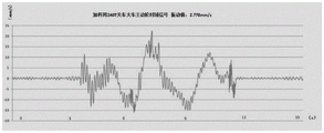
S5-1: the rail gnawing model is selected, the crown block runs under the condition of constant speed, the crown block enters a smooth rail (without joint) X5=180 meters to X6=220 meters, the rail gnawing phenomenon of wheels exists in the rail, when the crown block enters the position of the rail X5, the main lifting tonnage is 160W, the running speed of the crown block is 0.4m/s, the condition of the rail gnawing model is met at the moment, and the high-speed collector starts to collect bearing vibration signals until the crown block runs to the position of the rail X6.
S5-2: analyzing a rail gnawing model, wherein the overhead traveling crane runs at a constant speed, the tonnage of main lifting is 160W, the running speed of the overhead traveling crane is 0.4m/s, meanwhile, under the state that the trolley and lifting are kept to stop acting, the overhead traveling crane starts to collect 2-3 meters before entering the rail gnawing position, and finishes collecting after entering a smooth section for about 2-3 meters after passing the rail gnawing, a high-speed collector transmits collected vibration signals to a computer, and analysis and judgment software of overhead traveling crane wheels and a rail degradation system analyzes the data:
when the vibration value a (mm/s) (the lower graph 2.778 mm/s) exceeds a0=0.536 (mm/s), the values of the both-end time T3 and T4 are taken in the trend of the gnawing rail model, and the joint spacing is calculated by multiplying the running speed V =0.4 (m/s) of the crown block by Δ T2:
ΔT2= T4-T3=11.5-3.8=7.7(s)
ΔX2=ΔT2×V=7.7(s)×0.4(m/s)=3.08m
and calculating the length of the rail gnawing length of 3.08m, and comparing the measured rail gnawing data with standard and original rail gnawing vibration data to form a wheel rail gnawing model, as shown in fig. 6.
The method realizes real-time monitoring of the vibration condition of the wheels in online operation, quantifies the wheel bearing degradation vibration value, the degradation value of the rail joint and the rail gnawing degree value of the wheels by logically analyzing the collected signals, outputs the standard exceeding judgment result by comparing the three measurement values with the preset standard value, and can combine each measurement value with the previous measurement value to form a change trend graph, thereby providing corresponding reference data for equipment maintenance, effectively avoiding the occurrence of crown block accidents and providing favorable help for the good operation of crown blocks.
Claims (6)
1. A method for automatically judging degradation of wheels and rails of a crown block, which is characterized by comprising the following steps:
and S1, setting the crown block to run at a constant speed: the crown block worker operates the crown block and uses the crown block to enter a constant-speed running state;
s2-1: auxiliary signal acquisition-overhead traveling crane operating position: a coding cable is laid on the outer side of the track, an overhead traveling crane walking position detector is mounted at an end beam of the overhead traveling crane, and when the overhead traveling crane runs to a certain position, the overhead traveling crane walking position detector identifies Gray codes on the cable, so that the specific position of the overhead traveling crane can be accurately read;
s2-2: auxiliary signal acquisition-acquisition of hoisting tonnage: a weight sensor is arranged at the supporting position of a fixed pulley bearing seat of the main hoisting system, and the weight of a hoisted heavy object is displayed through a secondary measuring instrument;
s2-3: auxiliary signal acquisition-acquisition of the running speed of the crown block: the method comprises the following steps that when a crown block is in a constant-speed running state, a crown block walks by a first-gear running signal collector to collect running signals;
s3-1: selecting a bearing degradation model, wherein in the running process of the crown block, a running signal is 1, which indicates that the running condition of the crown block is met, presetting a smooth track position range without joints and a rail gnawing condition, when the crown block enters the starting point of the smooth track position range, the main lifting and hoisting tonnage is normal, meeting the condition of the bearing degradation model, and a signal high-speed collector collects a bearing vibration signal until the crown block runs to the end point of the smooth track position range;
s3-2: analyzing a bearing degradation model, namely selecting wheels of a cart working for about 1 year, driving a crown block from a starting point to an end point of a position range of a smooth track, enabling the main lifting tonnage to be normal, enabling the running speed of the crown block to be uniform, simultaneously keeping a trolley and lifting to be in a stop action state, transmitting vibration signals collected by a high-speed signal collector to a computer, and analyzing and judging software by a system for analyzing the wheels of the cart and the track degradation to form a wheel bearing vibration model; secondly, selecting wheels of a large vehicle working for about 5 years, driving the crown block from a starting point to an end point of a position range of a smooth track, enabling the main lifting tonnage to be normal, enabling the crown block to run at a constant speed, simultaneously keeping the trolley and lifting to be in a stop action state, transmitting the vibration signals collected by the high-speed signal collector to a computer, and forming a wheel bearing vibration aging model after analysis of analysis judgment software of the wheels of the large vehicle and the track degradation system;
s4-1: selecting a track joint vibration model, wherein the main lifting tonnage is normal, the running speed of the overhead traveling crane is constant, and when the overhead traveling crane enters the track joint position, the signal high-speed collector starts to collect bearing vibration signals until the overhead traveling crane passes through the track joint position;
s4-2: analyzing a track joint vibration model, wherein the main lifting tonnage is normal, the running speed of a crown block is uniform, meanwhile, the crown block starts to collect from a position 0.5 m before entering the position of the track joint and finishes collecting after entering a smooth section about 0.5 m after passing through the track joint under the condition that a trolley and lifting are kept to stop acting, a high-speed collector transmits collected vibration signals to a computer, and analysis and judgment software of crown block wheels and a track degradation system analyzes the signals, calculates the width of the joint, and compares the measured joint distance with standard and original joint data to form a track joint degradation model;
s5-1: selecting a rail gnawing model, enabling the overhead traveling crane to run at a constant speed and enter a smooth rail with a wheel gnawing phenomenon, enabling the main lifting tonnage to be normal, enabling the overhead traveling crane to run at a constant speed, meeting the conditions of the rail gnawing model at the moment, and enabling a signal high-speed collector to start collecting bearing vibration signals until the overhead traveling crane runs through the wheel gnawing position before the overhead traveling crane enters the wheel gnawing position;
s5-2: analyzing a rail gnawing model, wherein the lifting and hoisting tonnage of a heavenly main is normal, the running speed of an overhead traveling crane is uniform, meanwhile, under the state that a trolley and lifting are kept to stop acting, the overhead traveling crane starts to collect from a position 2-3 meters before entering a rail gnawing position, enters a smooth section after passing the rail gnawing and finishes collecting after about 2-3 meters, a signal high-speed collector transmits collected vibration signals to a computer, analysis and judgment software of overhead traveling crane wheels and a rail degradation system analyzes the signals, the length of the gnawing rail is calculated, and the rail gnawing data is measured and compared with standard and original rail gnawing vibration data to form a wheel gnawing rail model;
and S6, according to the results of the analysis and judgment of the three models, measuring the standard exceeding alarm, and storing the data into an alarm recording module.
2. The method according to claim 1, wherein the method comprises the steps of: the device used by the method comprises an overhead traveling crane (1), an overhead traveling crane track (2), a track joint (3), an overhead traveling crane wheel bearing box vibration transmitter (4), a signal high-speed collector (5), a main lifting weight collector (6), an overhead traveling crane walking position detector (7), an overhead traveling crane walking first-gear operation signal collector (8) and overhead traveling crane wheel and track degradation system analysis and judgment software (9), wherein the overhead traveling crane wheel bearing box vibration transmitter (4) is installed on a corner box of a wheel bearing of the overhead traveling crane (1), and an output signal is connected to the signal high-speed collector (5); the input ends of a main lifting weight collector (6), a crown block walking position detector (7) and a crown block walking first-gear operation signal collector (8) are respectively connected with a crown block (1), and the output end is connected with a signal high-speed collector (5); the signal high-speed collector (5) is connected with the track deterioration system analysis and judgment software (9).
3. The method according to claim 2, wherein the method comprises the following steps: the vibration acquisition frequency of the crown block wheel bearing box vibration transmitter (4) is 1000 HZ.
4. The method according to claim 2, wherein the method comprises the following steps: the main lifting weight collector (6) comprises a weight sensor and a secondary measuring instrument, the weight sensor is supported by a fixed pulley bearing seat of a main lifting system of the overhead travelling crane, and an output weight signal is 0-1V; the crown block walking position detector (7) comprises a coding cable and a position detector, the coding cable is laid outside the crown block track (2), the position detector is installed at the end beam of the crown block, and an output position signal is 0-1V; the overhead traveling crane walking first gear operation signal collector (8) comprises an operation contactor, collects an auxiliary contact and outputs a switching value signal.
5. The method according to claim 1, wherein the method comprises the steps of: the signal high-speed collector (5) is a USB DAQ-580I type, the nonlinearity of the signal high-speed collector is +/-0.00030% FSR, four channels are adopted, and the sampling speed is as follows: 2.5sps-30 ksps.
6. The method according to claim 1, wherein the method comprises the steps of: the analysis and judgment software (9) of the crown block wheel and track degradation system is pyWhon language programming software and comprises a model selection module (91), a wheel bearing model (92), a track joint model (93), a wheel gnawing model (94) and an alarm recording module (95).
Priority Applications (1)
| Application Number | Priority Date | Filing Date | Title |
|---|---|---|---|
| CN202110534598.2A CN113353802B (en) | 2021-05-17 | 2021-05-17 | Device and method for automatically judging degradation of crown block wheel and track |
Applications Claiming Priority (1)
| Application Number | Priority Date | Filing Date | Title |
|---|---|---|---|
| CN202110534598.2A CN113353802B (en) | 2021-05-17 | 2021-05-17 | Device and method for automatically judging degradation of crown block wheel and track |
Publications (2)
| Publication Number | Publication Date |
|---|---|
| CN113353802A CN113353802A (en) | 2021-09-07 |
| CN113353802B true CN113353802B (en) | 2022-09-16 |
Family
ID=77526967
Family Applications (1)
| Application Number | Title | Priority Date | Filing Date |
|---|---|---|---|
| CN202110534598.2A Active CN113353802B (en) | 2021-05-17 | 2021-05-17 | Device and method for automatically judging degradation of crown block wheel and track |
Country Status (1)
| Country | Link |
|---|---|
| CN (1) | CN113353802B (en) |
Families Citing this family (2)
| Publication number | Priority date | Publication date | Assignee | Title |
|---|---|---|---|---|
| CN114180353B (en) * | 2021-12-28 | 2022-08-30 | 湖南天桥嘉成智能科技有限公司 | Multi-type material preparation unmanned overhead crane intelligent control system and method |
| CN114890075A (en) * | 2022-04-29 | 2022-08-12 | 弥费实业(上海)有限公司 | Device and method for monitoring walking state of air transport trolley |
Citations (8)
| Publication number | Priority date | Publication date | Assignee | Title |
|---|---|---|---|---|
| US3965733A (en) * | 1973-03-15 | 1976-06-29 | Pye Limited | Crane load inidicating arrangement |
| JPH101052A (en) * | 1996-06-14 | 1998-01-06 | Hitachi Ltd | Train passage alarming system |
| CN104760892A (en) * | 2014-01-06 | 2015-07-08 | 中国特种设备检测研究院 | Harbor crane health monitoring and forecasting visualization system |
| CN105152024A (en) * | 2015-09-14 | 2015-12-16 | 山东钢铁股份有限公司 | Overhead crane positioning system based on Gray code technology |
| CN206172819U (en) * | 2016-11-21 | 2017-05-17 | 中国神华能源股份有限公司 | Overhead traveling crane operating condition monitoring system |
| CN107215353A (en) * | 2017-05-26 | 2017-09-29 | 华东交通大学 | A kind of remote monitoring method for early warning of track structure disease |
| CN108975163A (en) * | 2018-09-30 | 2018-12-11 | 武汉冶钢结构有限责任公司 | A kind of method of bridge crane wheel group operational safety detection |
| CN110482406A (en) * | 2018-05-15 | 2019-11-22 | 宝山钢铁股份有限公司 | A kind of railway monitoring system and method for hoisting machinery dynamic operation |
-
2021
- 2021-05-17 CN CN202110534598.2A patent/CN113353802B/en active Active
Patent Citations (8)
| Publication number | Priority date | Publication date | Assignee | Title |
|---|---|---|---|---|
| US3965733A (en) * | 1973-03-15 | 1976-06-29 | Pye Limited | Crane load inidicating arrangement |
| JPH101052A (en) * | 1996-06-14 | 1998-01-06 | Hitachi Ltd | Train passage alarming system |
| CN104760892A (en) * | 2014-01-06 | 2015-07-08 | 中国特种设备检测研究院 | Harbor crane health monitoring and forecasting visualization system |
| CN105152024A (en) * | 2015-09-14 | 2015-12-16 | 山东钢铁股份有限公司 | Overhead crane positioning system based on Gray code technology |
| CN206172819U (en) * | 2016-11-21 | 2017-05-17 | 中国神华能源股份有限公司 | Overhead traveling crane operating condition monitoring system |
| CN107215353A (en) * | 2017-05-26 | 2017-09-29 | 华东交通大学 | A kind of remote monitoring method for early warning of track structure disease |
| CN110482406A (en) * | 2018-05-15 | 2019-11-22 | 宝山钢铁股份有限公司 | A kind of railway monitoring system and method for hoisting machinery dynamic operation |
| CN108975163A (en) * | 2018-09-30 | 2018-12-11 | 武汉冶钢结构有限责任公司 | A kind of method of bridge crane wheel group operational safety detection |
Also Published As
| Publication number | Publication date |
|---|---|
| CN113353802A (en) | 2021-09-07 |
Similar Documents
| Publication | Publication Date | Title |
|---|---|---|
| CN113353802B (en) | Device and method for automatically judging degradation of crown block wheel and track | |
| CN202400737U (en) | Hoisting machinery online safety monitoring recorder | |
| CN204434006U (en) | The operating safety convenience instrument of a kind of elevator | |
| CN103274303B (en) | Control method for hoisting machinery safety monitoring and management system | |
| CN104803250A (en) | Anti-falling monitoring device, monitoring system and method for elevator | |
| CN109307601A (en) | A kind of vehicle braking ability wireless detecting system | |
| CN112550369A (en) | Switch application on-line state monitoring system | |
| CN204675554U (en) | Hoist falling-proof monitoring device | |
| CN212558958U (en) | Elevator traction machine fault determination system based on current monitoring technology | |
| CN114771601B (en) | Method for monitoring displacement of indicating rod of close-fitting inspector | |
| CN116359327A (en) | Steel wire rope monitoring system based on artificial intelligence | |
| CN214935130U (en) | Steel wire rope nondestructive testing system and elevator with same | |
| CN110668312A (en) | Safety monitoring and structural health information management system for hoisting machinery | |
| CN214067015U (en) | Steel wire rope point inspection system of overhead manned device based on multiple sensors | |
| CN212425175U (en) | Anti-swing system of bridge crane | |
| CN210366704U (en) | Automatic control device of bridge crane | |
| CN211075906U (en) | Track fastener inefficacy real-time supervision device | |
| CN113942939A (en) | Double-beam crane and article conveying system adopting same | |
| JP2000079839A (en) | Impact measurement device | |
| CN203144853U (en) | Full-automatic precision monitoring device for geometric parameter variation | |
| CN112146698B (en) | Method for monitoring state of driving wheel | |
| CN115744622A (en) | System and method for measuring swing amount of crown block lifting fixed pulley | |
| CN117303211A (en) | Intelligent control system of bridge crane | |
| CN220549133U (en) | Road bridge automatic damage assessment vehicle based on ultrasonic rebound synthetic method | |
| CN219977332U (en) | Component detection device of portable crane |
Legal Events
| Date | Code | Title | Description |
|---|---|---|---|
| PB01 | Publication | ||
| PB01 | Publication | ||
| SE01 | Entry into force of request for substantive examination | ||
| SE01 | Entry into force of request for substantive examination | ||
| GR01 | Patent grant | ||
| GR01 | Patent grant |