CN113350925A - Dust exhaust device of power equipment dust remover - Google Patents
Dust exhaust device of power equipment dust remover Download PDFInfo
- Publication number
- CN113350925A CN113350925A CN202110761220.6A CN202110761220A CN113350925A CN 113350925 A CN113350925 A CN 113350925A CN 202110761220 A CN202110761220 A CN 202110761220A CN 113350925 A CN113350925 A CN 113350925A
- Authority
- CN
- China
- Prior art keywords
- steam
- dust
- air
- fixed
- mixing
- Prior art date
- Legal status (The legal status is an assumption and is not a legal conclusion. Google has not performed a legal analysis and makes no representation as to the accuracy of the status listed.)
- Granted
Links
- 239000000428 dust Substances 0.000 title claims abstract description 92
- 238000002156 mixing Methods 0.000 claims abstract description 66
- 238000001816 cooling Methods 0.000 claims abstract description 39
- XLYOFNOQVPJJNP-UHFFFAOYSA-N water Substances O XLYOFNOQVPJJNP-UHFFFAOYSA-N 0.000 claims description 51
- 230000000149 penetrating effect Effects 0.000 claims description 7
- 238000007599 discharging Methods 0.000 claims description 5
- 238000001914 filtration Methods 0.000 claims description 3
- 239000008213 purified water Substances 0.000 claims description 3
- 230000001376 precipitating effect Effects 0.000 claims description 2
- 230000000694 effects Effects 0.000 abstract description 7
- 239000012535 impurity Substances 0.000 abstract description 4
- 238000004887 air purification Methods 0.000 abstract description 2
- 239000007788 liquid Substances 0.000 abstract description 2
- 238000005507 spraying Methods 0.000 description 3
- 238000010586 diagram Methods 0.000 description 2
- 230000009123 feedback regulation Effects 0.000 description 2
- 238000012423 maintenance Methods 0.000 description 2
- 238000000034 method Methods 0.000 description 2
- 238000000746 purification Methods 0.000 description 2
- -1 thermal power plants Substances 0.000 description 2
- 241000208125 Nicotiana Species 0.000 description 1
- 235000002637 Nicotiana tabacum Nutrition 0.000 description 1
- 238000003915 air pollution Methods 0.000 description 1
- 239000010426 asphalt Substances 0.000 description 1
- 230000009286 beneficial effect Effects 0.000 description 1
- 239000004566 building material Substances 0.000 description 1
- 238000005266 casting Methods 0.000 description 1
- 239000004568 cement Substances 0.000 description 1
- 238000004140 cleaning Methods 0.000 description 1
- 230000008602 contraction Effects 0.000 description 1
- 239000000498 cooling water Substances 0.000 description 1
- 238000004090 dissolution Methods 0.000 description 1
- 238000003754 machining Methods 0.000 description 1
- 238000005272 metallurgy Methods 0.000 description 1
- 239000003595 mist Substances 0.000 description 1
- 239000000126 substance Substances 0.000 description 1
Images
Classifications
-
- B—PERFORMING OPERATIONS; TRANSPORTING
- B01—PHYSICAL OR CHEMICAL PROCESSES OR APPARATUS IN GENERAL
- B01D—SEPARATION
- B01D47/00—Separating dispersed particles from gases, air or vapours by liquid as separating agent
- B01D47/05—Separating dispersed particles from gases, air or vapours by liquid as separating agent by condensation of the separating agent
-
- Y—GENERAL TAGGING OF NEW TECHNOLOGICAL DEVELOPMENTS; GENERAL TAGGING OF CROSS-SECTIONAL TECHNOLOGIES SPANNING OVER SEVERAL SECTIONS OF THE IPC; TECHNICAL SUBJECTS COVERED BY FORMER USPC CROSS-REFERENCE ART COLLECTIONS [XRACs] AND DIGESTS
- Y02—TECHNOLOGIES OR APPLICATIONS FOR MITIGATION OR ADAPTATION AGAINST CLIMATE CHANGE
- Y02A—TECHNOLOGIES FOR ADAPTATION TO CLIMATE CHANGE
- Y02A50/00—TECHNOLOGIES FOR ADAPTATION TO CLIMATE CHANGE in human health protection, e.g. against extreme weather
- Y02A50/20—Air quality improvement or preservation, e.g. vehicle emission control or emission reduction by using catalytic converters
- Y02A50/2351—Atmospheric particulate matter [PM], e.g. carbon smoke microparticles, smog, aerosol particles, dust
Abstract
The invention discloses a dust exhaust device of a dust remover of electrical equipment, which comprises a bracket, wherein a mixing cavity is fixed on the bracket, a steam mixing component is fixed in the bracket on the outer wall of the mixing cavity, one end of the steam mixing component is connected with an air inlet pipe, the other end of the steam mixing component is connected with a steam generator fixed in the bracket, and the output end of the steam mixing component penetrates into the mixing cavity; the mixing chamber is provided with a cooling chamber above, the cooling chamber is provided with a gas collection chamber above, a plurality of cooling pipes which are vertically arranged are distributed on the plane in the cooling chamber, and the cooling pipes penetrate through the upper surface and the lower surface of the cooling chamber to enable the gas collection chamber to be communicated with the mixing chamber. Compared with the prior art, the invention can efficiently collect and condense dust in the air to be treated into liquid by steam, has good air purification effect and high dust exhaust efficiency, and is water-saving and environment-friendly. The mixing proportion of the steam and the air to be treated can be adjusted, so that the steam can better dissolve impurities such as dust in the air to be treated.
Description
Technical Field
The invention relates to the technical field of power equipment, in particular to a dust exhaust device of a dust remover of the power equipment.
Background
The dust remover is widely used for dust removing operation in various fields of metallurgy, mines, cement, thermal power plants, building materials, casting, chemical industry, pharmaceutical industry, tobacco, asphalt mixing machines, grain, machining and the like, and the dust remover needs to perform dust removing and cleaning work after working for a certain time, so that the dust remover recovers the initial dust removing function. However, since the dust remover is in a continuous operation state, the discharged air with dust is insufficiently cleaned during the dust discharging process of the dust remover, and the dust is liable to pollute the environment.
In the prior art, the air discharged is purified by the filter devices such as the filter screen, the air pollution environment with dust can be avoided, but the filter screen needs to be replaced frequently, the maintenance is troublesome, the cost is high, the blockage is easy, and the passing rate is low. In the prior art, dust is collected in a mode of dissolving dust in air by spraying in the air to be treated, continuous operation can be realized, maintenance is avoided, but the spraying and the dust in the air to be treated are poor in solubility, the dust in the air cannot be well dissolved, the purification effect is poor, and more water needs to be consumed by continuous spraying.
Therefore, it is necessary to provide a dust discharging device of a dust remover for electric equipment to solve the problems in the background art.
Disclosure of Invention
In order to achieve the purpose, the invention provides the following technical scheme: a dust exhaust device of a dust remover of electrical equipment comprises a bracket, wherein a mixing cavity is fixed on the bracket, a steam mixing component is fixed in the bracket on the outer wall of the mixing cavity, one end of the steam mixing component is connected with an air inlet pipe, the other end of the steam mixing component is connected with a steam generator fixed in the bracket, and the output end of the steam mixing component penetrates into the mixing cavity;
the mixing chamber is provided with a cooling chamber above, the cooling chamber is provided with a gas collection chamber above, a plurality of cooling pipes which are vertically arranged are distributed on the plane in the cooling chamber, and the cooling pipes penetrate through the upper surface and the lower surface of the cooling chamber to enable the gas collection chamber to be communicated with the mixing chamber.
Further, as preferred, the gas collection cavity is conductively connected with a guide pipe, the other end of the guide pipe is connected to the input end of the exhaust fan, and the output end of the exhaust fan is connected with a vertical exhaust pipe.
Furthermore, as a preferred option, a funnel-shaped collecting hopper is connected below the mixing cavity in a penetrating manner, the outlet end of the collecting hopper is connected to the water tank, a filtering and precipitating device is arranged in the water tank, and purified water is sent to the input end of the steam generator through a circulating pump.
Further, as a preferred option, a water inlet is formed in the side face below the cooling cavity, a water outlet is formed in the diagonal direction of the water inlet above the cooling cavity, and the water inlet and the water outlet are connected to an external water source through a water pump.
Further, preferably, the steam mixing assembly comprises an upper fixed disk, a lower fixed ring is arranged below the upper fixed disk, and a plurality of vertically arranged air guide grids are uniformly distributed on the circumference between the upper fixed disk and the lower fixed ring;
the periphery of the upper fixing disc and the periphery of the lower fixing ring are provided with two steam channels and two air channels which are arranged in opposite directions, the steam channels and the air channels are spiral channels which are spirally towards the opening direction of the air guide grating, the peripheries of the upper fixing disc and the lower fixing ring are halved and completely and hermetically surrounded by the steam channels, the steam channels are connected with a steam generator, and the air channels are connected with an air inlet pipe.
Furthermore, as preferred, every air guide grid's last lower extreme and last fixed disk and lower fixed ring rotationally be connected, and its upper end runs through the upper fixed disk and fixed connection to be located the rotary cover of upper fixed disk top in, be fixed with connecting rod one in the rotary cover, the one end that the rotary cover was kept away from to connecting rod one articulates there is connecting rod two to make upper fixed disk top around there being the round rotary cover connecting rod one and connecting rod two.
Furthermore, preferably, a raised sleeve is fixed in the center of the upper fixed disk, a lower rotating ring and an upper rotating ring which are vertically separated are rotatably sleeved on the periphery of the sleeve, and the lower rotating ring and the upper rotating ring are respectively positioned above and below the second connecting rod;
one ends, far away from the first connecting rod, of the second connecting rod of the half circle corresponding to the direction of the steam channel are respectively and uniformly hinged on the edge of the upper rotating ring, and one ends, far away from the first connecting rod, of the second connecting rod of the other half circle corresponding to the direction of the air channel are respectively and uniformly hinged on the edge of the lower rotating ring.
Further, preferably, an upper adjusting pin is fixedly arranged on the upper rotating ring, the upper adjusting pin is connected with the support through an upper adjusting cylinder, a cylinder body of the upper adjusting cylinder is hinged with the support, and the tail end of a piston rod of the upper adjusting cylinder is hinged with the upper adjusting pin;
an arc-shaped through groove is formed in the upper rotating ring, a lower adjusting pin which penetrates through the through groove and is fixedly connected with the lower rotating ring is arranged in the through groove, the lower adjusting pin is connected with the support through a lower adjusting cylinder, the cylinder body of the lower adjusting cylinder is hinged with the support, and the tail end of the piston rod of the lower adjusting cylinder is hinged with the lower adjusting pin.
Furthermore, preferably, a rotating shaft penetrating through the upper fixed disk is arranged at the center of the circle of the upper fixed disk, the rotating shaft is rotatably connected with the fixed disk and the sleeve, and a conical exhaust impeller is fixed on the rotating shaft in the annular part enclosed by the air guide grids;
one end of the rotating shaft, which is far away from the exhaust impeller, is connected to an output shaft of a driving motor, and the driving motor is fixedly connected with the support.
Further, as preferred, be equipped with dust concentration sensor in the gas collection chamber, just dust concentration sensor can carry out feedback control to the mixing ratio of steam and the air to be treated in the steam mixing subassembly.
Compared with the prior art, the invention has the beneficial effects that:
according to the invention, when the steam mixing component mixes steam and air to be dedusted and dissolves dust to form and the mixed steam enters the gas collecting cavity from the gas collecting cavity through the cooling pipe, the temperature of the mixed steam is suddenly reduced due to the circulating cold water in the cooling cavity, so that the steam with the dust dissolved is condensed, clean air enters the gas collecting cavity and is discharged by the exhaust fan, and the condensed water mixed with the dust falls into the collecting hopper and flows into the water tank, so that the dust in the air to be treated can be efficiently collected and condensed into liquid by the steam, the air purification effect is good, and the dust exhaust efficiency is high;
the condensed water flowing into the water tank is purified and then is regenerated into steam through the steam generator, so that the steam can be recycled, the water consumption in the dust exhaust process is small, and the water-saving and environment-friendly effects are achieved.
According to the invention, the upper rotating ring or the lower rotating ring can be driven to rotate by the expansion of the upper adjusting cylinder or the lower adjusting cylinder, so that the upper rotating ring or the lower rotating ring drives the corresponding half-circle connecting rod I and the corresponding connecting rod II to pull the rotating cover to rotate, the corresponding half-circle air guide grid in the steam channel or the air channel rotates to adjust the flow rates of the steam channel and the air channel, the mixing ratio of the steam and the air to be treated is adjusted, the steam can better dissolve impurities such as dust in the air to be treated, and the dust exhaust effect is ensured to be good;
and the mixing ratio of the steam and the air to be treated is subjected to feedback regulation by a dust concentration sensor in the air collecting cavity, so that high dust discharging efficiency and good purification effect of the discharged air can be ensured.
Drawings
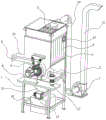
FIG. 1 is a schematic structural diagram of a dust discharging device of a dust remover for electrical equipment;
FIG. 2 is a schematic structural diagram of a steam mixing component of a dust exhaust device of a dust remover for electrical equipment;
FIG. 3 is a schematic sectional view of a steam mixing component of a dust exhaust device of a dust remover for electric equipment;
in the figure: 1. a support; 2. a mixing chamber; 3. a cooling chamber; 31. a water inlet; 32. a water outlet; 4. a cooling tube; 5. a gas collection cavity; 6. a steam mixing assembly; 7. an exhaust fan; 8. an air inlet pipe; 9. a drive motor; 10. a water tank; 11. an exhaust pipe; 12. a steam generator; 13. a circulation pump; 14. a conduit; 15. a collecting hopper; 61. an upper fixed disc; 62. a lower fixing ring; 63. a steam channel; 64. an air passage; 65. an air guide grid; 66. a rotating shaft; 67. a sleeve; 68. a lower swivel; 681. a lower adjustment pin; 682. a lower adjustment cylinder; 69. an upper swivel; 691. an upper adjustment pin; 692. an upper adjusting cylinder; 610. a through groove; 611. rotating the cover; 612. a first connecting rod; 613. a second connecting rod; 614. an exhaust impeller.
Detailed Description
Referring to fig. 1, in an embodiment of the present invention, a dust exhaust apparatus of a dust remover for electrical equipment includes a support 1, a mixing chamber 2 is fixed on the support 1, a steam mixing component 6 is fixed in the support 1 on an outer wall of the mixing chamber 2, one end of the steam mixing component 6 is connected to an air inlet pipe 8, the other end of the steam mixing component 6 is connected to a steam generator 12 fixed in the support 1, and an output end of the steam mixing component 6 penetrates through the mixing chamber 2;
the cooling cavity 3 is arranged above the mixing cavity 2, the gas collecting cavity 5 is arranged above the cooling cavity 3, a plurality of vertically arranged cooling pipes 4 are distributed on the plane in the cooling cavity 3, and the cooling pipes 4 penetrate through the upper surface and the lower surface of the cooling cavity 3, so that the gas collecting cavity 5 is communicated with the mixing cavity 2.
In this embodiment, the gas collecting cavity 5 is conductively connected with a conduit 14, the other end of the conduit 14 is connected to an input end of an exhaust fan 7, and an output end of the exhaust fan 7 is connected with a vertical exhaust pipe 11.
In this embodiment, a funnel-shaped collecting hopper 15 is connected to the lower portion of the mixing chamber 2 in a penetrating manner, the outlet end of the collecting hopper 15 is connected to the water tank 10, a filtering and settling device is arranged in the water tank 10, and the purified water is sent to the input end of the steam generator 12 through the circulating pump 13.
In this embodiment, a water inlet 31 is formed in the side surface below the cooling cavity 3, a water outlet 32 is formed in the diagonal direction of the water inlet 31 above the cooling cavity 3, and the water inlet 31 and the water outlet 32 are connected to an external water source through a water pump;
that is, when the steam mixing assembly 6 mixes steam with air to be dedusted and dissolves dust to form and mixed steam enters the gas collecting chamber 5 from the gas collecting chamber 5 through the cooling pipe 4, the temperature of the mixed steam is abruptly lowered due to circulating cold water in the cooling chamber 3, so that the steam with the dust dissolved therein is condensed, clean air enters the gas collecting chamber 5 and is discharged by the exhaust fan 7, and the condensed water with the dust mixed therein falls into the collecting hopper 15 and flows into the water tank 10, and is purified and then again passes through the steam generator 12 to generate steam.
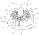
Referring to fig. 2, in the present embodiment, the steam mixing assembly 6 includes an upper fixing disk 61, a lower fixing ring 62 is disposed below the upper fixing disk 61, and a plurality of vertically arranged air guide grills 65 are uniformly distributed around the circumference between the upper fixing disk 61 and the lower fixing ring 62;
the peripheries of the upper fixed disk 61 and the lower fixed disk 62 are provided with two steam channels 63 and air channels 64 which are oppositely arranged, the steam channels 63 and the air channels 64 are spiral channels which are spirally towards the opening direction of the air guide grille 65, the peripheries of the upper fixed disk 61 and the lower fixed disk 62 are halved and completely and hermetically enclosed by the steam channels 63 and the air channels 64, the steam channels 63 are connected with the steam generator 12, and the air channels 64 are connected with the air inlet pipe 8;
that is, the gas introduced into the steam passage 63 and the air passage 64 can be introduced into the interiors of the upper fixed disk 61 and the lower fixed disk 62 by being guided by the gas guide grill 65.
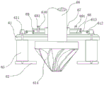
Referring to fig. 2 and 3, in the present embodiment, the upper end and the lower end of each air guide grille 65 are rotatably connected to the upper fixed tray 61 and the lower fixed tray 62, the upper end of each air guide grille penetrates through the upper fixed tray 61 and is fixedly connected to the rotating cover 611 located above the upper fixed tray 61, a first connecting rod 612 is fixed in the rotating cover 611, and one end of the first connecting rod 612, which is far away from the rotating cover 611, is hinged to a second connecting rod 613, so that a circle of rotating cover 611, the first connecting rod 612 and the second connecting rod 613 surround the upper fixed tray 61.
In this embodiment, a convex sleeve 67 is fixed in the center of the upper fixed disk 61, a lower rotating ring 68 and an upper rotating ring 69 which are vertically spaced are rotatably sleeved on the periphery of the sleeve 67, and the lower rotating ring 68 and the upper rotating ring 69 are respectively located above and below the second connecting rod 613;
the ends of the second half-turn connecting rods 613, which are far away from the first connecting rods 612, corresponding to the direction of the steam channel 63 are respectively and uniformly hinged on the edge of the upper rotating ring 69, and the ends of the second half-turn connecting rods 613, which are far away from the first connecting rods 612, corresponding to the direction of the air channel 64 are respectively and uniformly hinged on the edge of the lower rotating ring 68.
In this embodiment, an upper adjusting pin 691 is fixedly disposed on the upper swivel 69, the upper adjusting pin 691 is connected to the bracket 1 through an upper adjusting cylinder 692, a cylinder body of the upper adjusting cylinder 692 is hinged to the bracket 1, and a distal end of a piston rod of the upper adjusting cylinder 692 is hinged to the upper adjusting pin 691;
an arc-shaped through groove 610 is formed in the upper rotating ring 69, a lower adjusting pin 681 which penetrates through the through groove 610 and is fixedly connected with the lower rotating ring 68 is arranged in the through groove 610, the lower adjusting pin 681 is connected with the bracket 1 through a lower adjusting cylinder 682, the cylinder body of the lower adjusting cylinder 682 is hinged with the bracket 1, and the tail end of the piston rod of the lower adjusting cylinder 682 is hinged with the lower adjusting pin 681;
that is to say, through the extension and contraction of the upper adjusting cylinder 692 or the lower adjusting cylinder 682, the upper rotating ring 69 or the lower rotating ring 68 can be driven to rotate, so that the upper rotating ring drives the corresponding half-turn first connecting rod 612 and the corresponding half-turn second connecting rod 613 to pull the rotating cover 611 to rotate, and the corresponding half-turn air guide grille 65 in the steam channel 63 or the air channel 64 rotates to adjust the flow rates of the steam channel 63 and the air channel 64, so that the mixing ratio of the steam and the air to be treated is adjusted, the steam can better dissolve impurities such as dust in the air to be treated, and the good dust exhaust effect is ensured.
In this embodiment, a rotating shaft 66 penetrating the upper fixed disk 61 is arranged at the center of the circle, the rotating shaft 66 is rotatably connected with the fixed disk 61 and the sleeve 67, and a conical exhaust impeller 614 is fixed on the rotating shaft 66 in the annular part enclosed by the air guide grille 65;
one end of the rotating shaft 66 far away from the exhaust impeller 614 is connected to an output shaft of a driving motor 9, and the driving motor 9 is fixedly connected with the bracket 1.
In this embodiment, be equipped with dust concentration sensor in the gas collecting cavity 5, just dust concentration sensor can carry out feedback control to the mixing ratio of steam and the air to be treated in the steam mixing subassembly 6.
The rotation of the exhaust impeller 614 can generate vortex airflow, so that the steam and the air to be treated can be mixed more uniformly, and the dissolution of impurities such as dust in the air to be treated by the steam is accelerated.
During specific implementation, the exhaust end of the dust remover of the electrical equipment is connected into the air inlet pipe 8, circulating cooling water is introduced into the cooling cavity 3 through the water inlet 31 and the water outlet 32, and the steam generator 12 heats water fed from the water tank 10 to generate steam;
the exhaust fan 7 starts to exhaust air, and because a closed space is formed among the air collecting cavity 5, the mixing cavity 2, the collecting hopper 15 and the water tank 10, a one-way airflow channel for exhausting air from the steam mixing component 6 to the mixing cavity 2, the air collecting cavity 5, the guide pipe 14 to the exhaust pipe 11 is generated in the device;
when the steam mixing component 6 mixes steam and air to be dedusted and dissolves dust to form and mixed steam enters the gas collecting cavity 5 from the gas collecting cavity 5 through the cooling pipe 4, the temperature of the mixed steam is suddenly reduced due to circulating cold water in the cooling cavity 3, so that the steam with the dissolved dust is condensed, clean air enters the gas collecting cavity 5 and is discharged by the exhaust fan 7, and the condensed water with the mixed dust falls into the collecting hopper 15 and flows into the water tank 10, and is purified and then passes through the steam generator 12 again to generate steam;
wherein, the steam mixing component 6 is subjected to feedback regulation of a dust concentration sensor, and the feedback is as follows: when dust concentration sensor discerned dust concentration too high, adjustment steam mixing assembly 6 reduced the admission volume of pending air, increased the admission volume of steam to reduce the content of dust in the mist, and dust concentration sensor discerned dust concentration when lower, increased the admission volume of pending air, reduced the admission volume of steam, in order to improve the efficiency of dust exhaust, its specific regulative mode is:
the upper rotating ring 69 or the lower rotating ring 68 can be driven to rotate by the expansion of the upper adjusting cylinder 692 or the lower adjusting cylinder 682, so that the corresponding half-turn connecting rod I612 and the corresponding half-turn connecting rod II 613 are driven to pull the rotating cover 611 to rotate, and the corresponding half-turn air guide grille 65 in the steam channel 63 or the air channel 64 is rotated, so as to adjust the flow rates of the steam channel 63 and the air channel 64, and further adjust the mixing ratio of the steam and the air to be treated.
The above description is only for the preferred embodiment of the present invention, but the scope of the present invention is not limited thereto, and any person skilled in the art should be considered to be within the technical scope of the present invention, and the technical solutions and the inventive concepts thereof according to the present invention are equivalent to or changed within the technical scope of the present invention.
Claims (10)
1. The dust exhaust device of the dust remover for the electric power equipment comprises a support (1) and is characterized in that a mixing cavity (2) is fixed on the support (1), a steam mixing component (6) is fixed in the support (1) on the outer wall of the mixing cavity (2), one end of the steam mixing component (6) is connected with an air inlet pipe (8), the other end of the steam mixing component is connected with a steam generator (12) fixed in the support (1), and the output end of the steam mixing component (6) penetrates through the mixing cavity (2);
mixing chamber (2) top is cooling chamber (3), cooling chamber (3) top is gas collection chamber (5), cooling chamber (3) internal plane distributes has many vertical cooling tubes (4) of arranging, cooling tube (4) run through the top and bottom of cooling chamber (3), make gas collection chamber (5) and mixing chamber (2) switch on.
2. The dust exhaust device of the electric power equipment dust remover according to claim 1, characterized in that the gas collecting cavity (5) is conductively connected with a conduit (14), the other end of the conduit (14) is connected to the input end of an exhaust fan (7), and the output end of the exhaust fan (7) is connected with a vertical exhaust pipe (11).
3. The dust exhaust device of the electric power equipment dust remover according to claim 1, characterized in that a funnel-shaped collecting hopper (15) is connected below the mixing chamber (2) in a penetrating manner, the outlet end of the collecting hopper (15) is connected to a water tank (10), a filtering and precipitating device is arranged in the water tank (10), and purified water is sent to the input end of the steam generator (12) through a circulating pump (13).
4. The dust exhaust device of the dust remover of the electric equipment as claimed in claim 1, wherein a water inlet (31) is formed on the side surface below the cooling cavity (3), a water outlet (32) is formed on the diagonal direction of the water inlet (31) above the cooling cavity (3), and the water inlet (31) and the water outlet (32) are connected to an external water source through a water pump.
5. The dust exhaust device of the dust remover of the electric equipment as claimed in claim 1, wherein the steam mixing assembly (6) comprises an upper fixed disk (61), a lower fixed ring (62) is arranged below the upper fixed disk (61), and a plurality of vertically arranged air guide grids (65) are uniformly distributed on the circumference between the upper fixed disk (61) and the lower fixed ring (62);
the periphery of the upper fixing disc (61) and the periphery of the lower fixing disc (62) are provided with two steam channels (63) and two air channels (64) which are arranged in opposite directions, the steam channels (63) and the air channels (64) are spiral channels which are spirally towards the opening direction of the air guide grille (65), the peripheries of the upper fixing disc (61) and the lower fixing disc (62) are halved by the steam channels (63) and are completely and hermetically surrounded, the steam channels (63) are connected with the steam generator (12), and the air channels (64) are connected with the air inlet pipe (8).
6. The dust discharging device of the electric power equipment dust remover according to claim 5, wherein each air guide grille (65) has upper and lower ends rotatably connected with the upper fixed tray (61) and the lower fixed tray (62), and has an upper end penetrating through the upper fixed tray (61) and fixedly connected to the rotating cover (611) above the upper fixed tray (61), the rotating cover (611) has a first connecting rod (612) fixed therein, and an end of the first connecting rod (612) far away from the rotating cover (611) is hinged with a second connecting rod (613), so that the rotating cover (611), the first connecting rod (612) and the second connecting rod (613) are surrounded above the upper fixed tray (61).
7. The dust exhaust device of the dust remover of the electric power equipment as claimed in claim 6, wherein a raised sleeve (67) is fixed in the center of the upper fixed disc (61), a lower rotary ring (68) and an upper rotary ring (69) which are spaced up and down are rotatably sleeved on the periphery of the sleeve (67), and the lower rotary ring (68) and the upper rotary ring (69) are respectively positioned above and below the second connecting rod (613);
one ends, far away from the connecting rod I (612), of the half circle of the connecting rod II (613) corresponding to the direction of the steam channel (63) are respectively and uniformly hinged on the edge of the upper rotating ring (69), and one ends, far away from the connecting rod I (612), of the other half circle of the connecting rod II (613) corresponding to the direction of the air channel (64) are respectively and uniformly hinged on the edge of the lower rotating ring (68).
8. The dust exhaust apparatus of electric power equipment dust remover according to claim 7, characterized in that said upper rotating ring (69) is fixed with an upper adjusting pin (691), said upper adjusting pin (691) is connected with the bracket (1) through an upper adjusting cylinder (692), the cylinder body of said upper adjusting cylinder (692) is hinged with the bracket (1), the end of the piston rod of said upper adjusting cylinder (692) is hinged with the upper adjusting pin (691);
go up swivel (69) and open curved logical groove (610) of having seted up, be equipped with in logical groove (610) and run through it and with lower swivel (68) fixed connection's lower adjusting pin (681), adjusting pin (681) is connected with support (1) through adjusting cylinder (682) down, the cylinder body and support (1) of adjusting cylinder (682) are articulated down, the piston rod end of adjusting cylinder (682) is articulated with adjusting pin (681) down.
9. The dust exhaust device of the dust remover for the electric equipment as claimed in claim 5, wherein a rotating shaft (66) penetrating through the upper fixed disc (61) is arranged at the center of the circle, the rotating shaft (66) is rotatably connected with the fixed disc (61) and a sleeve (67), and a conical exhaust impeller (614) is fixed on the part of the rotating shaft (66) in the ring shape enclosed by the air guide grille (65);
one end, far away from the exhaust impeller (614), of the rotating shaft (66) is connected to an output shaft of a driving motor (9), and the driving motor (9) is fixedly connected with the support (1).
10. The dust exhaust device of the electric power equipment dust remover according to claim 1, wherein a dust concentration sensor is arranged in the gas collecting cavity (5), and the dust concentration sensor can perform feedback adjustment on the mixing ratio of the steam and the air to be treated in the steam mixing component (6).
Priority Applications (1)
| Application Number | Priority Date | Filing Date | Title |
|---|---|---|---|
| CN202110761220.6A CN113350925B (en) | 2021-07-06 | 2021-07-06 | Dust exhaust device of power equipment dust remover |
Applications Claiming Priority (1)
| Application Number | Priority Date | Filing Date | Title |
|---|---|---|---|
| CN202110761220.6A CN113350925B (en) | 2021-07-06 | 2021-07-06 | Dust exhaust device of power equipment dust remover |
Publications (2)
| Publication Number | Publication Date |
|---|---|
| CN113350925A true CN113350925A (en) | 2021-09-07 |
| CN113350925B CN113350925B (en) | 2022-05-17 |
Family
ID=77538387
Family Applications (1)
| Application Number | Title | Priority Date | Filing Date |
|---|---|---|---|
| CN202110761220.6A Active CN113350925B (en) | 2021-07-06 | 2021-07-06 | Dust exhaust device of power equipment dust remover |
Country Status (1)
| Country | Link |
|---|---|
| CN (1) | CN113350925B (en) |
Cited By (1)
| Publication number | Priority date | Publication date | Assignee | Title |
|---|---|---|---|---|
| CN113877308A (en) * | 2021-11-16 | 2022-01-04 | 华北电力大学(保定) | Negative-pressure air-exhaust efficient filtering device |
Citations (6)
| Publication number | Priority date | Publication date | Assignee | Title |
|---|---|---|---|---|
| US5101847A (en) * | 1989-10-31 | 1992-04-07 | Yoshinori Oribe | Method and apparatus for equalizing airflow velocity |
| CN101109295A (en) * | 2007-08-02 | 2008-01-23 | 寿光市康跃增压器有限公司 | Composite spray of variable cross-section turbosupercharger |
| CN201358960Y (en) * | 2009-01-21 | 2009-12-09 | 长沙埃尔压缩机有限责任公司 | Blade type diffuser and high-speed centrifugal blower therewith |
| CN105999918A (en) * | 2016-07-13 | 2016-10-12 | 方龙旺 | Tiny dust particle filtration and adsorption system |
| CN208678740U (en) * | 2018-08-28 | 2019-04-02 | 山东铂佳轻合金有限公司 | Waste gas produced device when a kind of processing melting waste aluminum |
| CN209900926U (en) * | 2019-05-06 | 2020-01-07 | 湖南有色郴州萤石球团有限公司 | Dust removal device for overhigh water vapor |
-
2021
- 2021-07-06 CN CN202110761220.6A patent/CN113350925B/en active Active
Patent Citations (6)
| Publication number | Priority date | Publication date | Assignee | Title |
|---|---|---|---|---|
| US5101847A (en) * | 1989-10-31 | 1992-04-07 | Yoshinori Oribe | Method and apparatus for equalizing airflow velocity |
| CN101109295A (en) * | 2007-08-02 | 2008-01-23 | 寿光市康跃增压器有限公司 | Composite spray of variable cross-section turbosupercharger |
| CN201358960Y (en) * | 2009-01-21 | 2009-12-09 | 长沙埃尔压缩机有限责任公司 | Blade type diffuser and high-speed centrifugal blower therewith |
| CN105999918A (en) * | 2016-07-13 | 2016-10-12 | 方龙旺 | Tiny dust particle filtration and adsorption system |
| CN208678740U (en) * | 2018-08-28 | 2019-04-02 | 山东铂佳轻合金有限公司 | Waste gas produced device when a kind of processing melting waste aluminum |
| CN209900926U (en) * | 2019-05-06 | 2020-01-07 | 湖南有色郴州萤石球团有限公司 | Dust removal device for overhigh water vapor |
Cited By (2)
| Publication number | Priority date | Publication date | Assignee | Title |
|---|---|---|---|---|
| CN113877308A (en) * | 2021-11-16 | 2022-01-04 | 华北电力大学(保定) | Negative-pressure air-exhaust efficient filtering device |
| CN113877308B (en) * | 2021-11-16 | 2022-11-11 | 华北电力大学(保定) | Negative-pressure air-exhaust efficient filtering device |
Also Published As
| Publication number | Publication date |
|---|---|
| CN113350925B (en) | 2022-05-17 |
Similar Documents
| Publication | Publication Date | Title |
|---|---|---|
| CN113350925B (en) | Dust exhaust device of power equipment dust remover | |
| CN218130692U (en) | Waste gas treatment device for vacuum brazing furnace | |
| CN204180906U (en) | A kind of fish meal makes production line | |
| CN116793081A (en) | Electric stove with automatic slag removal structure | |
| CN109354366B (en) | Sludge treatment equipment adopting catalytic wet oxidation method | |
| CN110864564B (en) | Steam condensate recovery device of potassium chlorate refining technology | |
| CN110056924B (en) | Cyclone separation type oil fume purification device | |
| CN115446091A (en) | Method for rapidly recovering mercury from mercury-containing waste residues | |
| CN211936189U (en) | Dust collector is used in special fertilizer production in flower nursery | |
| CN211189485U (en) | Exhaust-gas treatment is with filtering bellows | |
| CN113476962A (en) | Energy-saving and carbon-reducing integral solution technology and system device for iron and steel enterprise | |
| CN209848424U (en) | Metallurgical stove cooling water collection cycle recycles device | |
| CN210057731U (en) | Water curtain dust removal device for powder feeding | |
| CN111888878A (en) | Waste gas treatment device for waste incineration | |
| CN218077114U (en) | Tail gas treatment device for innocent treatment | |
| CN220334803U (en) | Industrial sewage treatment equipment | |
| CN219744282U (en) | Workshop smoke dust collecting and purifying device | |
| CN220125585U (en) | Sewage discharge filter | |
| CN218452013U (en) | RCO heat accumulating type catalytic combustion equipment for organic waste gas | |
| CN214020066U (en) | Exhaust treatment device of thermal power plant | |
| CN218636792U (en) | Carousel formula dross removal mechanism | |
| CN219454698U (en) | Calcining kiln waste heat recovery equipment | |
| CN219804364U (en) | Dust collecting equipment convenient to clearance | |
| CN219098770U (en) | Energy-saving device for treating industrial sewage by activated sludge process | |
| CN218774537U (en) | A filtration equipment for thermal power plant's flue gas is handled |
Legal Events
| Date | Code | Title | Description |
|---|---|---|---|
| PB01 | Publication | ||
| PB01 | Publication | ||
| SE01 | Entry into force of request for substantive examination | ||
| SE01 | Entry into force of request for substantive examination | ||
| GR01 | Patent grant | ||
| GR01 | Patent grant | ||
| PE01 | Entry into force of the registration of the contract for pledge of patent right | ||
| PE01 | Entry into force of the registration of the contract for pledge of patent right |
Denomination of invention: A dust removal device for power equipment dust collectors Effective date of registration: 20231107 Granted publication date: 20220517 Pledgee: Agricultural Bank of China Limited Nanjing Qixia Branch Pledgor: JIANGSU GLENS SCIENCES AND TECHNOLOGY CO.,LTD. Registration number: Y2023980064084 |