CN113340990A - Tunnel lining quality safety inspection device - Google Patents
Tunnel lining quality safety inspection device Download PDFInfo
- Publication number
- CN113340990A CN113340990A CN202110661031.1A CN202110661031A CN113340990A CN 113340990 A CN113340990 A CN 113340990A CN 202110661031 A CN202110661031 A CN 202110661031A CN 113340990 A CN113340990 A CN 113340990A
- Authority
- CN
- China
- Prior art keywords
- plate
- frame
- sliding
- tunnel lining
- support frame
- Prior art date
- Legal status (The legal status is an assumption and is not a legal conclusion. Google has not performed a legal analysis and makes no representation as to the accuracy of the status listed.)
- Granted
Links
- 238000007689 inspection Methods 0.000 title claims description 6
- 238000001514 detection method Methods 0.000 claims abstract description 43
- 230000000670 limiting effect Effects 0.000 claims abstract description 24
- 230000000903 blocking effect Effects 0.000 claims description 10
- 230000007246 mechanism Effects 0.000 claims description 9
- 230000005284 excitation Effects 0.000 claims description 8
- 230000000694 effects Effects 0.000 claims description 3
- 230000000087 stabilizing effect Effects 0.000 claims description 3
- 238000009434 installation Methods 0.000 abstract description 3
- 238000005259 measurement Methods 0.000 abstract description 2
- 230000006872 improvement Effects 0.000 description 7
- 230000001681 protective effect Effects 0.000 description 4
- 238000010030 laminating Methods 0.000 description 2
- 239000000463 material Substances 0.000 description 2
- 238000000034 method Methods 0.000 description 2
- 230000008569 process Effects 0.000 description 2
- 238000005299 abrasion Methods 0.000 description 1
- 230000004075 alteration Effects 0.000 description 1
- 230000009286 beneficial effect Effects 0.000 description 1
- 238000010276 construction Methods 0.000 description 1
- 238000010586 diagram Methods 0.000 description 1
- 238000005516 engineering process Methods 0.000 description 1
- 238000001125 extrusion Methods 0.000 description 1
- 230000007774 longterm Effects 0.000 description 1
- 238000012986 modification Methods 0.000 description 1
- 230000004048 modification Effects 0.000 description 1
- 230000001105 regulatory effect Effects 0.000 description 1
- 239000011435 rock Substances 0.000 description 1
- 238000006467 substitution reaction Methods 0.000 description 1
- XLYOFNOQVPJJNP-UHFFFAOYSA-N water Substances O XLYOFNOQVPJJNP-UHFFFAOYSA-N 0.000 description 1
- 238000003466 welding Methods 0.000 description 1
Images


Classifications
-
- G—PHYSICS
- G01—MEASURING; TESTING
- G01N—INVESTIGATING OR ANALYSING MATERIALS BY DETERMINING THEIR CHEMICAL OR PHYSICAL PROPERTIES
- G01N29/00—Investigating or analysing materials by the use of ultrasonic, sonic or infrasonic waves; Visualisation of the interior of objects by transmitting ultrasonic or sonic waves through the object
- G01N29/04—Analysing solids
-
- G—PHYSICS
- G01—MEASURING; TESTING
- G01N—INVESTIGATING OR ANALYSING MATERIALS BY DETERMINING THEIR CHEMICAL OR PHYSICAL PROPERTIES
- G01N29/00—Investigating or analysing materials by the use of ultrasonic, sonic or infrasonic waves; Visualisation of the interior of objects by transmitting ultrasonic or sonic waves through the object
- G01N29/22—Details, e.g. general constructional or apparatus details
- G01N29/26—Arrangements for orientation or scanning by relative movement of the head and the sensor
- G01N29/265—Arrangements for orientation or scanning by relative movement of the head and the sensor by moving the sensor relative to a stationary material
-
- G—PHYSICS
- G01—MEASURING; TESTING
- G01N—INVESTIGATING OR ANALYSING MATERIALS BY DETERMINING THEIR CHEMICAL OR PHYSICAL PROPERTIES
- G01N2291/00—Indexing codes associated with group G01N29/00
- G01N2291/02—Indexing codes associated with the analysed material
- G01N2291/023—Solids
- G01N2291/0232—Glass, ceramics, concrete or stone
Landscapes
- Physics & Mathematics (AREA)
- Health & Medical Sciences (AREA)
- Life Sciences & Earth Sciences (AREA)
- Chemical & Material Sciences (AREA)
- Analytical Chemistry (AREA)
- Biochemistry (AREA)
- General Health & Medical Sciences (AREA)
- General Physics & Mathematics (AREA)
- Immunology (AREA)
- Pathology (AREA)
- Acoustics & Sound (AREA)
- Lining And Supports For Tunnels (AREA)
Abstract
The invention relates to the technical field of tunnel measurement, in particular to a tunnel lining quality safety detection device which comprises a support frame and a movable support structure, wherein the movable support structure is connected in the support frame in a sliding mode and used for ensuring the fixed support of the support frame, the movable support structure comprises a sliding adjusting assembly, a lateral clamping structure and a limiting assembly, the limiting assembly is installed on one side of the support frame and used for adjusting the relative sliding between the sliding adjusting assembly and the support frame, one end of the sliding adjusting assembly is fixedly connected with the lateral clamping structure, when the clamped lateral clamping structure is matched with the limiting assembly to fix the sliding adjusting assembly, the adjustment of the sliding adjusting assembly and the fixation of the support frame are achieved, and a detection module is fixedly installed on one side of the support frame. The device is suitable for vehicles with cargo hoppers of different structures, so that the installation range and the applicability of the device are improved.
Description
Technical Field
The invention relates to the technical field of tunnel measurement, in particular to a tunnel lining quality safety detection device.
Background
In the present road and railway construction engineering, a tunnel is often built in a mountain area. Tunnel lining refers to a permanent structure that supports and maintains the long-term stability and durability of a tunnel. The functions of the tunnel lining include: supporting and maintaining the stability of the tunnel; maintaining the space required for train operation; preventing the weathering of the surrounding rock; the influence of underground water is eliminated.
The existing tunnel lining quality safety detection device usually uses a vehicle welding ladder frame, personnel hold detection equipment by hand to carry out quality detection on tunnel lining at the ladder frame, and the existing tunnel lining quality safety detection device lacks the capability of flexibly installing on vehicles of different specifications.
Therefore, the technical personnel in the field propose a tunnel lining quality safety detection device to solve the problems proposed in the background.
Disclosure of Invention
The invention aims to provide a tunnel lining quality safety detection device to solve the problems in the background technology.
In order to achieve the purpose, the invention provides the following technical scheme:
the utility model provides a tunnel lining quality safety inspection device, includes the support frame, still includes:
the movable support structure is connected in the support frame in a sliding mode and used for ensuring fixed support of the support frame, the movable support structure comprises a sliding adjusting assembly, a lateral clamping structure and a limiting assembly, the limiting assembly used for adjusting relative sliding of the sliding adjusting assembly and the support frame is installed on one side of the support frame, one end of the sliding adjusting assembly is fixedly connected with the lateral clamping structure, the lateral clamping structure comprises a folding frame, the folding frame is fixedly connected with a fixed plate and a fixed frame, the fixed frame is elastically connected with a push rod extending into the fixed frame, one end of the push rod is fixedly provided with a movable plate in a matching mode with the fixed plate, the circumferential side face of the push rod is fixedly provided with a machine handle, the machine handle is movably connected with a blocking groove structure arranged on the fixed frame, and when the machine handle rotates, the limiting effect of the blocking groove structure on the machine handle can be changed into the guiding effect of the blocking groove structure on the machine handle, the movable plate for clamping the side plate is driven by the ejector rod which is elastically driven by the fixed frame to move towards the fixed plate for clamping, and when the clamped lateral clamping structure is matched with the limiting assembly to fix the sliding adjusting assembly, the sliding adjusting assembly can be adjusted and the supporting frame can be fixed;
and the detection module is fixedly installed on one side of the support frame and is used for realizing the detection of the tunnel lining.
As a further improvement of the invention: the detection module comprises a protection box structure and a detection execution structure, wherein the detection execution structure arranged in the protection box structure comprises a motor-driven rotating platform which is connected with the protection box structure in a rotating mode, the rotating platform is connected with a stable frame structure, and the stable frame structure is connected with a detection head structure for detecting the quality of the tunnel lining.
As a further improvement of the invention: the sliding adjusting assembly comprises a transverse plate, a locking structure for limiting the folding frame to move in a certain distance is fixedly mounted on one side of the transverse plate, a sliding plate is fixedly connected to the other side of the transverse plate and is in sliding connection with the supporting frame, and the sliding plate is movably connected with the limiting assembly.
As a further improvement of the invention: the limiting assembly comprises a rotating disc, the rotating disc is rotatably connected with a sleeve, a threaded end of the rotating disc is in threaded connection with a pressing sleeve extending into the supporting frame, and the pressing sleeve is connected with the sliding plate.
As a further improvement of the invention: the protective box structure comprises a main box body, wherein the main box body is movably connected with box doors which are symmetrically arranged at the outer side of the main box body, the box doors are respectively hinged with a first hinged plate and a second hinged plate which are rotatably connected with the main box body, and the extending end of the first hinged plate, which is far away from the box doors, is hinged with a driving mechanism for driving the first hinged plate to rotate.
As a further improvement of the invention: the driving mechanism comprises a rotation driving assembly fixedly connected with the inner wall of the main box body, an output shaft of the rotation driving assembly is fixedly connected with a disc body, and the disc body is rotatably connected with a supporting plate hinged with the first hinge plate.
As a further improvement of the invention: the stabilizing frame structure comprises a bottom frame fixedly connected with the rotating table, a first driving unit is fixedly mounted on one side of the bottom frame, an output shaft of the first driving unit is fixedly connected with a rotating frame, a second driving unit is fixedly mounted at one end, far away from the bottom frame, of the rotating frame, an output shaft of the second driving unit is connected with an active telescopic rod structure, and an output rod of the active telescopic rod structure is fixedly connected with the detection head structure.
As a further improvement of the invention: the detection head structure comprises a groove plate fixedly connected with the driving telescopic rod structure, the groove plate is elastically connected with an arc plate, the arc side face of the arc plate is slidably connected with the groove of the arc shape of the groove plate, one side plane of the arc plate is connected with an elastic guide structure through a pressure plate, and one end of the elastic guide structure is fixedly provided with a sound wave excitation instrument array.
Compared with the prior art, the invention has the beneficial effects that:
the slip adjustment subassembly slides along the support frame and expandes, under the fixed of spacing subassembly, the slip adjustment subassembly is fixed, then the cooperation through keeping off groove structure and handle, can be with the keeping off groove structure department of the fender position of handle joint in different positions, under the elastic pulling of mount, the handle slides in keeping off the groove structure, the ejector pin drives the two-way clamp of fly leaf cooperation fixed plate and gets the vehicle sideboard, thereby accomplish the quick break away from and fix the vehicle sideboard, the device is adjusted through the cooperation of slip adjustment subassembly and side direction chucking structure, make the device be applicable to the vehicle that different structure goods were fought, thereby promote the installation scope and the suitability of the device.
Drawings
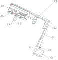
FIG. 1 is a schematic perspective view of the present invention;
FIG. 2 is a schematic perspective view of the locking mechanism of the present invention in cooperation with a lateral clamping mechanism;
FIG. 3 is a schematic view of the internal structure of the protective case structure of the present invention;
FIG. 4 is a schematic structural view of a stop assembly of the present invention;
FIG. 5 is a schematic diagram of a test execution architecture according to the present invention;
fig. 6 is a schematic structural view of the detection head structure of the present invention in cooperation with the driving telescopic rod structure.
In the figure: 1. a transverse plate; 3. a main box body; 4. a box door; 5. a support frame; 7. a slide plate; 8. a sleeve; 9. rotating the disc; 10. an active telescopic rod structure; 11. pressing the sleeve; 12. a groove blocking structure; 14. a second hinge plate; 15. a first hinge plate; 16. a support plate; 17. a tray body; 18. a rotation drive assembly; 19. locking the connecting frame; 20. a knob structure; 21. a fixing plate; 22. folding the frame; 23. a movable plate; 24. a handle; 25. a fixed mount; 26. a top rod; 27. a rotating table; 28. a chassis; 29. a rotating frame; 30. a first drive unit; 31. a second drive unit; 32. a groove plate; 33. an arc plate; 34. an elastic guide structure; 35. an acoustic wave vibration exciter array; 36. a pressure plate; 37. and (5) a locking structure.
Detailed Description
The technical solution of the present patent will be described in further detail with reference to the following embodiments.
In one embodiment, referring to fig. 1 to 6, a tunnel lining quality safety inspection device includes a support frame 5, and further includes:
the movable support structure is connected in the support frame 5 in a sliding manner and used for ensuring the fixed support of the support frame 5, the movable support structure comprises a sliding adjusting assembly, a lateral clamping structure and a limiting assembly, the limiting assembly used for adjusting the relative sliding between the sliding adjusting assembly and the support frame 5 is arranged on one side of the support frame 5, one end of the sliding adjusting assembly is fixedly connected with the lateral clamping structure, the lateral clamping structure comprises a folding frame 22, the folding frame 22 is fixedly connected with a fixed plate 21 and a fixed frame 25, the fixed frame 25 is elastically connected with an ejector rod 26 extending into the fixed frame 25, one end of the ejector rod 26 is fixedly installed with a movable plate 23 in a manner of being matched with the fixed plate 21, a machine handle 24 is fixedly installed on the circumferential side surface of the ejector rod 26, the machine handle 24 is movably connected with a blocking groove structure 12 arranged on the fixed frame 25, when the machine handle 24 rotates, the limiting effect of the blocking groove structure 12 on the machine handle 24 is changed into the guiding effect of the blocking groove structure 12 on the machine handle 24, the movable plate 23 for clamping the side plate is driven by the mandril 26 which is elastically driven by the fixed frame 25 to move and clamp towards the fixed plate 21, and when the clamped lateral clamping structure is matched with the limiting assembly to fix the sliding adjusting assembly, the adjustment of the sliding adjusting assembly and the fixation of the supporting frame 5 can be realized;
and the detection module is fixedly arranged on one side of the support frame 5 and is used for realizing the detection of the tunnel lining.
The slip adjustment subassembly expandes along 5 slides of support frame, under spacing subassembly's is fixed, then through the cooperation of keeping off groove structure 12 and handle 24, can be with the keeping off groove structure 12 department of the fender position of handle 24 joint in different positions, under the elastic pulling of mount 25, handle 24 slides in keeping off groove structure 12, ejector pin 26 drives 23 two-way clamps of fly leaf cooperation fixed plate 21 and gets the vehicle sideboard, thereby accomplish the quick break away from and fix the vehicle sideboard, the device is adjusted through the cooperation of slip adjustment subassembly and side direction chucking structure, make the device be applicable to the vehicle that different structure goods fought, thereby promote the installation scope and the suitability of the device.
In one aspect of this embodiment, the detection module includes the guard box structure and detects the implementation structure, the detection implementation structure of installing in the guard box structure includes the motor drive who is connected with the guard box structure rotation and rotates platform 27, it is connected with firm frame structure to rotate platform 27, firm frame structural connection has the detection head structure that detects the tunnel lining quality. In the process of traveling, the protective box structure is unfolded, and the rotating table 27 rotates the raised steady frame structure, so that the detection head structure is attached to the tunnel lining structure for detection.
In one aspect of this embodiment, the sliding adjustment assembly includes a transverse plate 1, a locking structure 37 for limiting the movement of the folding frame 22 within a certain distance is fixedly mounted on one side of the transverse plate 1, a sliding plate 7 slidably connected with the support frame 5 is fixedly connected on the other side of the transverse plate 1, and the sliding plate 7 is movably connected with the limiting assembly. The locking structure 37 adjusts the position of the folding frame 22 to match the length of the support frame 5 at the extension of the sliding plate 7, thereby adjusting the movable support structure.
In one aspect of this embodiment, the limiting assembly includes a rotary disk 9, the rotary disk 9 is rotatably connected with a sleeve 8, a threaded end of the rotary disk 9 is threadedly connected with a pressing sleeve 11 extending into the support frame 5, and the pressing sleeve 11 is connected with the sliding plate 7. The sleeve 8 is held to drive the rotating disc 9, the sleeve 8 and the rotating disc 9 rotate relatively, hands are protected from abrasion, and then the sliding plate 7 is pressed downwards by the pressing sleeve 11 under the driving of the threaded end of the rotating disc 9 to fix the sliding plate 7.
In one aspect of this embodiment, the locking structure 37 includes a locking link 19 that is sleeved over the folder 22 and a knob structure 20 that is threaded onto the locking link 19. The knob structure 20 is rotated to screw-fasten the folding frame 22 in the fastening link frame 19, thereby completing the adjustment of the extension length of the folding frame 22.
In one aspect of this embodiment, the protective box structure includes a main box body 3, the main box body 3 is movably connected with box doors 4 symmetrically installed outside the main box body 3, the box doors 4 are respectively hinged with a first hinged plate 15 and a second hinged plate 14 rotatably connected with the main box body 3, and an extending end of the first hinged plate 15 away from the box doors 4 is hinged with a driving mechanism for driving the first hinged plate 15 to rotate. The driving mechanism drives the first hinged plate 15, the box doors 4 are separated from each other under the driving of the common guide of the first hinged plate 15 and the second hinged plate 14, the quick opening of the box doors 4 is completed, and the detection executing structure is protected by the protection box structure in the transportation process.
In one aspect of the present embodiment, the driving mechanism includes a rotary driving assembly 18 fixedly connected to the inner wall of the main housing 3, an output shaft of the rotary driving assembly 18 is fixedly connected to a disc 17, and the disc 17 is rotatably connected to a fulcrum plate 16 hinged to the first hinge plate 15. The output shaft of the rotation driving assembly 18 drives the disc body 17 to rotate circumferentially around the output shaft of the rotation driving assembly 18, so as to drive the support plate 16 to deflect and push against the first hinge plate 15, and thus, the rotation of the first hinge plate 15 is driven.
In one aspect of this embodiment, the surface of the tray 17 is circumferentially provided with a plurality of sets of through holes. The through holes on the surface of the disc body 17 reduce the energy required for driving the disc body 17, and are energy-saving and environment-friendly.
In a case of this embodiment, the steady frame structure includes the chassis 28 with the revolving stage 27 fixed connection, one side fixed mounting of chassis 28 has first drive unit 30, the output shaft fixedly connected with rotating turret 29 of first drive unit 30, the one end fixed mounting that chassis 28 was kept away from to rotating turret 29 has second drive unit 31, the output shaft of second drive unit 31 has initiative telescopic link structure 10, the output pole and the detection head structure fixed connection of initiative telescopic link structure 10. First drive unit and second drive unit can preferably be the rotation motor, also preferably pneumatic revolving cylinder, rotate through the revolving stage 27 and drive chassis 28 rotatory, and the revolving rack 29 that first drive unit 30 drive was put to one side rotates to upright commentaries on classics attitude, and initiative telescopic link structure 10 and second drive unit 31 all are lifted outside main box 3 this moment, and then second drive unit 31 drive initiative telescopic link structure 10 pivoted the time, and initiative telescopic link structure 10 extends and promotes detection head structure lifting height.
In one aspect of this embodiment, the detection head structure includes a groove plate 32 fixedly connected to the active telescopic rod structure 10, the groove plate 32 is elastically connected to an arc plate 33, an arc-shaped side surface of the arc plate 33 is slidably connected to a groove of the groove plate 32 in an arc shape, a side plane of the arc plate 33 is connected to an elastic guide structure 34 through a pressure plate 36, the elastic guide structure 34 may be an extension member externally sleeved with a spring, and may also be an elastic block, and one end of the elastic guide structure 34 is fixedly mounted with a sound wave excitation instrument array 35. Along with the laminating tunnel wall of sound wave excitation appearance array 35, sound wave excitation appearance array 35 receives the extrusion to drive arc 33 frid 32 and deflect, accomplish the automatically regulated to sound wave excitation appearance array 35 laminating angle, the elastic guide structure 34 that receives simultaneously conducts the pressure that receives to pressure plate 36 and detects, in time judges the pressure that detects sound wave excitation appearance array 35 and receives, thereby protection sound wave excitation appearance array 35.
In the description herein, references to the description of the term "one embodiment," "some embodiments," "an example," "a specific example," or "some examples," etc., mean that a particular feature, structure, material, or characteristic described in connection with the embodiment or example is included in at least one embodiment or example of the invention. In this specification, the schematic representations of the terms used above are not necessarily intended to refer to the same embodiment or example. Furthermore, the particular features, structures, materials, or characteristics described may be combined in any suitable manner in any one or more embodiments or examples. Furthermore, various embodiments or examples and features of different embodiments or examples described in this specification can be combined and combined by one skilled in the art without contradiction.
While embodiments of the invention have been shown and described, it will be understood by those of ordinary skill in the art that: various changes, modifications, substitutions and alterations can be made to the embodiments without departing from the principles and spirit of the invention, the scope of which is defined by the claims and their equivalents.
Claims (8)
1. The utility model provides a tunnel lining quality safety inspection device, includes the support frame, its characterized in that still includes:
the movable support structure is connected in the support frame in a sliding mode and used for ensuring fixed support of the support frame, the movable support structure comprises a sliding adjusting assembly, a lateral clamping structure and a limiting assembly, the limiting assembly used for adjusting relative sliding of the sliding adjusting assembly and the support frame is installed on one side of the support frame, one end of the sliding adjusting assembly is fixedly connected with the lateral clamping structure, the lateral clamping structure comprises a folding frame, the folding frame is fixedly connected with a fixed plate and a fixed frame, the fixed frame is elastically connected with a push rod extending into the fixed frame, one end of the push rod is fixedly provided with a movable plate in a matching mode with the fixed plate, the circumferential side face of the push rod is fixedly provided with a machine handle, the machine handle is movably connected with a blocking groove structure arranged on the fixed frame, and when the machine handle rotates, the limiting effect of the blocking groove structure on the machine handle can be changed into the guiding effect of the blocking groove structure on the machine handle, the movable plate for clamping the side plate is driven by the ejector rod which is elastically driven by the fixed frame to move towards the fixed plate for clamping, and when the clamped lateral clamping structure is matched with the limiting assembly to fix the sliding adjusting assembly, the sliding adjusting assembly can be adjusted and the supporting frame can be fixed;
and the detection module is fixedly installed on one side of the support frame and is used for realizing the detection of the tunnel lining.
2. The tunnel lining quality safety detection device according to claim 1, wherein the detection module comprises a protection box structure and a detection execution structure, the detection execution structure installed in the protection box structure comprises a motor-driven rotating table rotatably connected with the protection box structure, the rotating table is connected with a stabilizing frame structure, and the stabilizing frame structure is connected with a detection head structure for detecting tunnel lining quality.
3. The tunnel lining quality safety detection device according to claim 2, wherein the sliding adjustment assembly comprises a transverse plate, a locking structure for limiting movement of the folding frame within a certain distance is fixedly mounted on one side of the transverse plate, a sliding plate slidably connected with the support frame is fixedly connected to the other side of the transverse plate, and the sliding plate is movably connected with the limiting assembly.
4. The tunnel lining quality safety detection device according to claim 1, wherein the limiting assembly comprises a rotary disc, the rotary disc is rotatably connected with a sleeve, a threaded end of the rotary disc is in threaded connection with a pressing sleeve extending into the support frame, and the pressing sleeve is connected with the sliding plate.
5. The tunnel lining quality safety detection device according to claim 1 or 2, wherein the protection box structure comprises a main box body, the main box body is movably connected with box doors symmetrically arranged at the outer sides of the main box body, the box doors are respectively hinged with a first hinged plate and a second hinged plate which are rotatably connected with the main box body, and an extending end of the first hinged plate, which is far away from the box doors, is hinged with a driving mechanism for driving the first hinged plate to rotate.
6. The tunnel lining quality safety inspection device of claim 5, wherein the driving mechanism comprises a rotary driving assembly fixedly connected with the inner wall of the main box body, an output shaft of the rotary driving assembly is fixedly connected with a disc body, and the disc body is rotatably connected with a support plate hinged with the first hinge plate.
7. The tunnel lining quality safety detection device according to claim 1, wherein the steady frame structure comprises a bottom frame fixedly connected with the rotating platform, a first driving unit is fixedly mounted on one side of the bottom frame, a rotating frame is fixedly connected with an output shaft of the first driving unit, a second driving unit is fixedly mounted on one end, away from the bottom frame, of the rotating frame, an output shaft of the second driving unit is connected with a driving telescopic rod structure, and an output rod of the driving telescopic rod structure is fixedly connected with the detection head structure.
8. The tunnel lining quality safety detection device of claim 7, wherein the detection head structure comprises a slot plate fixedly connected with the active telescopic rod structure, the slot plate is elastically connected with an arc plate, the arc-shaped side surface of the arc plate is slidably connected with the arc-shaped groove of the slot plate, the plane surface of one side of the arc plate is connected with an elastic guide structure through a pressure plate, and one end of the elastic guide structure is fixedly provided with a sound wave excitation instrument array.
Priority Applications (1)
| Application Number | Priority Date | Filing Date | Title |
|---|---|---|---|
| CN202110661031.1A CN113340990B (en) | 2021-06-15 | 2021-06-15 | Tunnel lining quality safety detection device |
Applications Claiming Priority (1)
| Application Number | Priority Date | Filing Date | Title |
|---|---|---|---|
| CN202110661031.1A CN113340990B (en) | 2021-06-15 | 2021-06-15 | Tunnel lining quality safety detection device |
Publications (2)
| Publication Number | Publication Date |
|---|---|
| CN113340990A true CN113340990A (en) | 2021-09-03 |
| CN113340990B CN113340990B (en) | 2024-01-09 |
Family
ID=77477138
Family Applications (1)
| Application Number | Title | Priority Date | Filing Date |
|---|---|---|---|
| CN202110661031.1A Active CN113340990B (en) | 2021-06-15 | 2021-06-15 | Tunnel lining quality safety detection device |
Country Status (1)
| Country | Link |
|---|---|
| CN (1) | CN113340990B (en) |
Cited By (1)
| Publication number | Priority date | Publication date | Assignee | Title |
|---|---|---|---|---|
| CN114563480A (en) * | 2022-04-28 | 2022-05-31 | 四川蜀工公路工程试验检测有限公司 | Road concrete structure strength detection device |
Citations (11)
| Publication number | Priority date | Publication date | Assignee | Title |
|---|---|---|---|---|
| US20120169876A1 (en) * | 2009-08-28 | 2012-07-05 | Riegl Laser Measurement Systems Gmbh | Laser scanning device for mounting on the roof rack of a vehicle |
| CN105738893A (en) * | 2015-12-30 | 2016-07-06 | 中铁第四勘察设计院集团有限公司 | Vehicle-mounted tunnel lining radar detection device |
| CN106324102A (en) * | 2016-11-01 | 2017-01-11 | 金陵科技学院 | Acoustic emission flaw detection vehicle for tunnel |
| WO2017096770A1 (en) * | 2015-12-11 | 2017-06-15 | 山东科技大学 | Driving device of all-directional automatic weld seam flaw detection instrument and application thereof |
| CN109017517A (en) * | 2018-07-06 | 2018-12-18 | 中国铁建重工集团有限公司 | Vehicular lining quality of channel vehicle |
| CN109017590A (en) * | 2018-08-14 | 2018-12-18 | 邹圆圆 | One kind being easily installed new-energy automobile luggage carrier |
| CN109703477A (en) * | 2019-02-20 | 2019-05-03 | 成都西南交大研究院有限公司 | A kind of bracket, support equipment and support system |
| CN110774985A (en) * | 2019-10-25 | 2020-02-11 | 珠海高凌信息科技股份有限公司 | Environment emergency flow monitoring system |
| CN211478153U (en) * | 2019-06-04 | 2020-09-11 | 中南大学 | Tunnel lining quality safety inspection device |
| CN211617578U (en) * | 2019-12-23 | 2020-10-02 | 苏交科集团检测认证有限公司 | Tunnel lining quality detection support |
| CN111999384A (en) * | 2020-08-01 | 2020-11-27 | 天津新亚太工程建设监理有限公司 | Tunnel lining cavity detection device and method |
-
2021
- 2021-06-15 CN CN202110661031.1A patent/CN113340990B/en active Active
Patent Citations (11)
| Publication number | Priority date | Publication date | Assignee | Title |
|---|---|---|---|---|
| US20120169876A1 (en) * | 2009-08-28 | 2012-07-05 | Riegl Laser Measurement Systems Gmbh | Laser scanning device for mounting on the roof rack of a vehicle |
| WO2017096770A1 (en) * | 2015-12-11 | 2017-06-15 | 山东科技大学 | Driving device of all-directional automatic weld seam flaw detection instrument and application thereof |
| CN105738893A (en) * | 2015-12-30 | 2016-07-06 | 中铁第四勘察设计院集团有限公司 | Vehicle-mounted tunnel lining radar detection device |
| CN106324102A (en) * | 2016-11-01 | 2017-01-11 | 金陵科技学院 | Acoustic emission flaw detection vehicle for tunnel |
| CN109017517A (en) * | 2018-07-06 | 2018-12-18 | 中国铁建重工集团有限公司 | Vehicular lining quality of channel vehicle |
| CN109017590A (en) * | 2018-08-14 | 2018-12-18 | 邹圆圆 | One kind being easily installed new-energy automobile luggage carrier |
| CN109703477A (en) * | 2019-02-20 | 2019-05-03 | 成都西南交大研究院有限公司 | A kind of bracket, support equipment and support system |
| CN211478153U (en) * | 2019-06-04 | 2020-09-11 | 中南大学 | Tunnel lining quality safety inspection device |
| CN110774985A (en) * | 2019-10-25 | 2020-02-11 | 珠海高凌信息科技股份有限公司 | Environment emergency flow monitoring system |
| CN211617578U (en) * | 2019-12-23 | 2020-10-02 | 苏交科集团检测认证有限公司 | Tunnel lining quality detection support |
| CN111999384A (en) * | 2020-08-01 | 2020-11-27 | 天津新亚太工程建设监理有限公司 | Tunnel lining cavity detection device and method |
Cited By (1)
| Publication number | Priority date | Publication date | Assignee | Title |
|---|---|---|---|---|
| CN114563480A (en) * | 2022-04-28 | 2022-05-31 | 四川蜀工公路工程试验检测有限公司 | Road concrete structure strength detection device |
Also Published As
| Publication number | Publication date |
|---|---|
| CN113340990B (en) | 2024-01-09 |
Similar Documents
| Publication | Publication Date | Title |
|---|---|---|
| EP3127765B1 (en) | Vehicle battery clamping device | |
| CN113340990A (en) | Tunnel lining quality safety inspection device | |
| CN115535056A (en) | Flying attaching machine box installation vehicle | |
| CN108269955A (en) | A kind of new-energy automobile lithium battery fixing device | |
| US20200353870A1 (en) | Storage device for a vehicle cab | |
| CN220199334U (en) | Transition transfer car (buggy) of stable steering of smoke and dust prevention | |
| CN109399518B (en) | Platform device of making an uproar falls in construction | |
| JP4890942B2 (en) | Opening and closing door device | |
| CN109374561B (en) | Infrared signal receiving and transmitting assembly of atmosphere detection vehicle | |
| CN114858005B (en) | Unmanned aerial vehicle countering defense system | |
| CN107984033A (en) | Vertical multi-angle fully automatic cutting machine | |
| CN110554219A (en) | Wave recording instrument fixed mounting mechanism | |
| CN109175999A (en) | To the assembling structure and assembly method of axis mechanism, robot assembly | |
| KR101651149B1 (en) | Adjustable angle jig device for a vehicle seat assembly | |
| CN109531731B (en) | Pin-connected panel nailing system | |
| CN216202490U (en) | Portable hand-held inflating device | |
| CA2493413A1 (en) | Drive for a sliding door or a swinging-sliding door | |
| CN214843620U (en) | Noise testing device | |
| CN221743889U (en) | Navigation mark lamp with anti-collision structure | |
| CN117231102B (en) | Double-convolution folding type flat sliding door structure | |
| CN211442501U (en) | Self-fixing hinge structure and automobile | |
| CN218949504U (en) | Platform driving mechanism for aircraft passenger ladder | |
| CN217505462U (en) | Rigidity detection device for front face mask of automobile | |
| CN213002363U (en) | Portable supporting platform for cable maintenance and detection | |
| CN220050630U (en) | Brake pedal arm welding assembly |
Legal Events
| Date | Code | Title | Description |
|---|---|---|---|
| PB01 | Publication | ||
| PB01 | Publication | ||
| SE01 | Entry into force of request for substantive examination | ||
| SE01 | Entry into force of request for substantive examination | ||
| GR01 | Patent grant | ||
| GR01 | Patent grant |