CN113339405B - Thin oil lubrication one-way thrust conical sliding bearing - Google Patents
Thin oil lubrication one-way thrust conical sliding bearing Download PDFInfo
- Publication number
- CN113339405B CN113339405B CN202110579175.2A CN202110579175A CN113339405B CN 113339405 B CN113339405 B CN 113339405B CN 202110579175 A CN202110579175 A CN 202110579175A CN 113339405 B CN113339405 B CN 113339405B
- Authority
- CN
- China
- Prior art keywords
- bearing
- oil
- inner ring
- outer ring
- face
- Prior art date
- Legal status (The legal status is an assumption and is not a legal conclusion. Google has not performed a legal analysis and makes no representation as to the accuracy of the status listed.)
- Active
Links
Images


Classifications
-
- F—MECHANICAL ENGINEERING; LIGHTING; HEATING; WEAPONS; BLASTING
- F16—ENGINEERING ELEMENTS AND UNITS; GENERAL MEASURES FOR PRODUCING AND MAINTAINING EFFECTIVE FUNCTIONING OF MACHINES OR INSTALLATIONS; THERMAL INSULATION IN GENERAL
- F16C—SHAFTS; FLEXIBLE SHAFTS; ELEMENTS OR CRANKSHAFT MECHANISMS; ROTARY BODIES OTHER THAN GEARING ELEMENTS; BEARINGS
- F16C25/00—Bearings for exclusively rotary movement adjustable for wear or play
- F16C25/02—Sliding-contact bearings
- F16C25/04—Sliding-contact bearings self-adjusting
-
- F—MECHANICAL ENGINEERING; LIGHTING; HEATING; WEAPONS; BLASTING
- F16—ENGINEERING ELEMENTS AND UNITS; GENERAL MEASURES FOR PRODUCING AND MAINTAINING EFFECTIVE FUNCTIONING OF MACHINES OR INSTALLATIONS; THERMAL INSULATION IN GENERAL
- F16C—SHAFTS; FLEXIBLE SHAFTS; ELEMENTS OR CRANKSHAFT MECHANISMS; ROTARY BODIES OTHER THAN GEARING ELEMENTS; BEARINGS
- F16C17/00—Sliding-contact bearings for exclusively rotary movement
- F16C17/10—Sliding-contact bearings for exclusively rotary movement for both radial and axial load
-
- F—MECHANICAL ENGINEERING; LIGHTING; HEATING; WEAPONS; BLASTING
- F16—ENGINEERING ELEMENTS AND UNITS; GENERAL MEASURES FOR PRODUCING AND MAINTAINING EFFECTIVE FUNCTIONING OF MACHINES OR INSTALLATIONS; THERMAL INSULATION IN GENERAL
- F16C—SHAFTS; FLEXIBLE SHAFTS; ELEMENTS OR CRANKSHAFT MECHANISMS; ROTARY BODIES OTHER THAN GEARING ELEMENTS; BEARINGS
- F16C17/00—Sliding-contact bearings for exclusively rotary movement
- F16C17/12—Sliding-contact bearings for exclusively rotary movement characterised by features not related to the direction of the load
- F16C17/24—Sliding-contact bearings for exclusively rotary movement characterised by features not related to the direction of the load with devices affected by abnormal or undesired positions, e.g. for preventing overheating, for safety
- F16C17/246—Sliding-contact bearings for exclusively rotary movement characterised by features not related to the direction of the load with devices affected by abnormal or undesired positions, e.g. for preventing overheating, for safety related to wear, e.g. sensors for measuring wear
-
- F—MECHANICAL ENGINEERING; LIGHTING; HEATING; WEAPONS; BLASTING
- F16—ENGINEERING ELEMENTS AND UNITS; GENERAL MEASURES FOR PRODUCING AND MAINTAINING EFFECTIVE FUNCTIONING OF MACHINES OR INSTALLATIONS; THERMAL INSULATION IN GENERAL
- F16C—SHAFTS; FLEXIBLE SHAFTS; ELEMENTS OR CRANKSHAFT MECHANISMS; ROTARY BODIES OTHER THAN GEARING ELEMENTS; BEARINGS
- F16C33/00—Parts of bearings; Special methods for making bearings or parts thereof
- F16C33/02—Parts of sliding-contact bearings
- F16C33/04—Brasses; Bushes; Linings
- F16C33/06—Sliding surface mainly made of metal
- F16C33/10—Construction relative to lubrication
- F16C33/1025—Construction relative to lubrication with liquid, e.g. oil, as lubricant
- F16C33/106—Details of distribution or circulation inside the bearings, e.g. details of the bearing surfaces to affect flow or pressure of the liquid
- F16C33/1065—Grooves on a bearing surface for distributing or collecting the liquid
-
- F—MECHANICAL ENGINEERING; LIGHTING; HEATING; WEAPONS; BLASTING
- F16—ENGINEERING ELEMENTS AND UNITS; GENERAL MEASURES FOR PRODUCING AND MAINTAINING EFFECTIVE FUNCTIONING OF MACHINES OR INSTALLATIONS; THERMAL INSULATION IN GENERAL
- F16C—SHAFTS; FLEXIBLE SHAFTS; ELEMENTS OR CRANKSHAFT MECHANISMS; ROTARY BODIES OTHER THAN GEARING ELEMENTS; BEARINGS
- F16C33/00—Parts of bearings; Special methods for making bearings or parts thereof
- F16C33/02—Parts of sliding-contact bearings
- F16C33/04—Brasses; Bushes; Linings
- F16C33/06—Sliding surface mainly made of metal
- F16C33/10—Construction relative to lubrication
- F16C33/1025—Construction relative to lubrication with liquid, e.g. oil, as lubricant
- F16C33/106—Details of distribution or circulation inside the bearings, e.g. details of the bearing surfaces to affect flow or pressure of the liquid
- F16C33/1085—Channels or passages to recirculate the liquid in the bearing
-
- F—MECHANICAL ENGINEERING; LIGHTING; HEATING; WEAPONS; BLASTING
- F16—ENGINEERING ELEMENTS AND UNITS; GENERAL MEASURES FOR PRODUCING AND MAINTAINING EFFECTIVE FUNCTIONING OF MACHINES OR INSTALLATIONS; THERMAL INSULATION IN GENERAL
- F16C—SHAFTS; FLEXIBLE SHAFTS; ELEMENTS OR CRANKSHAFT MECHANISMS; ROTARY BODIES OTHER THAN GEARING ELEMENTS; BEARINGS
- F16C33/00—Parts of bearings; Special methods for making bearings or parts thereof
- F16C33/02—Parts of sliding-contact bearings
- F16C33/04—Brasses; Bushes; Linings
- F16C33/06—Sliding surface mainly made of metal
- F16C33/10—Construction relative to lubrication
- F16C33/1095—Construction relative to lubrication with solids as lubricant, e.g. dry coatings, powder
Landscapes
- Engineering & Computer Science (AREA)
- General Engineering & Computer Science (AREA)
- Mechanical Engineering (AREA)
- Chemical & Material Sciences (AREA)
- Oil, Petroleum & Natural Gas (AREA)
- Sliding-Contact Bearings (AREA)
- Rolling Contact Bearings (AREA)
Abstract
The invention relates to a thin oil lubrication one-way thrust conical sliding bearing which comprises a bearing outer ring and a bearing inner ring which are matched and sleeved, wherein the outer peripheral surface of the bearing outer ring is a bearing outer wall, the inner peripheral surface of the bearing inner ring is a bearing inner wall, the matching surface between the bearing outer ring and the bearing inner ring is an outer ring friction conical surface, and the matching surface between the bearing inner ring and the bearing outer ring is an inner ring friction conical surface; the bearing comprises an outer ring friction conical surface and an inner ring friction conical surface, wherein the outer ring friction conical surface and the inner ring friction conical surface are both provided with solid super-lubricating coatings, the inner ring friction conical surface is provided with a function curve oil groove, the outer wall or the inner wall of the bearing is provided with an oil supply groove extending along the circumferential direction, a plurality of radial oil supply holes extending along the radial direction are arranged on the outer ring or the inner ring of the bearing at intervals along the circumferential direction, one end of each radial oil supply hole is communicated with the oil supply groove, and the other end of each radial oil supply hole is opened in the outer ring friction conical surface or the inner ring friction conical surface. The invention realizes super lubrication based on the matching of the liquid super-lubricity technology and the solid coating super-lubricity technology, and has excellent performance.
Description
Technical Field
The invention relates to a sliding bearing, in particular to a thin oil lubrication one-way thrust conical sliding bearing.
Background
The bearing is an important basic part of mechanical equipment, and all active mechanical equipment can not be separated from the bearing. Its basic function is that the supporting mechanism rotates, reduces the friction coefficient in its motion, guarantees its gyration precision. In order to reduce friction and improve efficiency in human labor production activities, a sliding bearing and a rolling bearing are invented in sequence. The invention relates to a sliding bearing, which is invented and used by human beings initially, and with the technological progress, the friction coefficient of the rolling bearing is found to be far lower than that of the sliding bearing, and then various rolling bearings are invented and used up to now. However, compared with the two bearings, except energy conservation caused by the fact that the friction coefficient of the rolling bearing is 2~3 orders of magnitude lower than that of the sliding bearing, the two bearings are not as good as the sliding bearing in all aspects, especially in aspects of manufacturing cost, service life, bearing capacity and the like. With the development of modern technology, especially the engineering application of ultra-low lubrication and super-lubrication technology, it is possible to replace the rolling bearing by the sliding bearing. On the other hand, due to the structural characteristics of the rolling element and the inner and outer ring raceways which are main parts of the rolling bearing, when in use, the surface of the rolling element is in point contact or line contact, and is influenced by factors such as vibration, uneven stress, scratches and the like, so that indentation and pitting on the contact surface are easily caused to form fatigue peeling and other damages, and the rotation precision is reduced, so that poor lubrication, friction and vibration are further aggravated, the rolling bearing enters a vicious working cycle, and the whole service life of the bearing is shortened.
With the development of modern technology, the requirements on bearings in mechanical equipment are higher and higher, and meanwhile, the modern technology also makes it possible to design and manufacture bearings which can meet the requirements on ultra high speed, large load, high rotation precision and large adaptive temperature range. At present, it has been found that there are two main types of materials with super-lubricating properties, one being a solid lubricating coating deposited on the surface of the material and the other being a liquid lubricant between the two material surfaces.
Disclosure of Invention
In order to overcome the defects in the prior art, the invention provides a thin oil lubrication one-way thrust conical sliding bearing which realizes the super-lubrication characteristic based on a liquid super-lubrication technology and a solid coating super-lubrication technology.
In order to achieve the purpose, the invention adopts the specific scheme that: a thin oil lubrication one-way thrust conical sliding bearing comprises a bearing outer ring and a bearing inner ring which are matched and sleeved, wherein the outer peripheral surface of the bearing outer ring is a bearing outer wall, the inner peripheral surface of the bearing inner ring is a bearing inner wall, the matching surface between the bearing outer ring and the bearing inner ring is an outer ring friction conical surface, and the matching surface between the bearing inner ring and the bearing outer ring is an inner ring friction conical surface; the bearing comprises an outer ring friction conical surface and an inner ring friction conical surface, wherein the outer ring friction conical surface and the inner ring friction conical surface are both provided with solid super-lubricating coatings, the inner ring friction conical surface is provided with a function curve oil groove, the outer wall of the bearing or the inner wall of the bearing is provided with an oil supply groove extending along the circumferential direction, a plurality of radial oil supply holes extending along the radial direction are arranged on the outer ring of the bearing or the inner ring of the bearing at intervals along the circumferential direction, one end of each radial oil supply hole is communicated with the oil supply groove, and the other end of each radial oil supply hole is opened on the outer ring friction conical surface or the inner ring friction conical surface and is communicated with the function curve oil groove.
As an option of the above technical solution, the radial oil supply hole is formed in the bearing outer ring, the oil supply groove is an outer ring middle oil supply groove formed in the bearing outer wall, and the radial oil supply hole is an outer ring radial oil supply hole formed in the bearing outer ring.
Furthermore, two sealing ring grooves extending along the circumferential direction are further formed in the outer wall of the bearing, and the two sealing ring grooves are located on two sides of the outer ring middle oil supply groove respectively.
Furthermore, the smaller one of the two end faces of the bearing outer ring is an outer ring small end face, the other end face is an outer ring large end face, the smaller one of the two end faces of the bearing inner ring is an inner ring small end face, and the other end face is an inner ring large end face.
Furthermore, an outer ring oil return groove is formed in the large end face of the outer ring, the outer ring oil return groove is an annular groove and is coaxial with the bearing outer ring, and the depth of the outer ring oil return groove is larger than or equal to the width of the end face gap.
The section of the outer ring middle oil supply groove is U-shaped or rectangular.
As another option of the above technical solution, the radial oil supply hole is formed in the bearing inner ring, the oil supply groove is a ring lower oil supply groove formed in the inner wall of the bearing, and the radial oil supply hole is an inner ring radial oil supply hole formed in the bearing inner ring.
Furthermore, the cross section of the ring lower oil supply groove is U-shaped or rectangular.
Furthermore, a plurality of oil inlets are further formed in the function curve oil groove, the diameter of each oil inlet is larger than the width of the function curve oil groove, and the oil inlets are alternately matched with the inner ring radial oil supply holes to communicate the oil supply groove under the ring with the function curve oil groove.
On the basis of the two selectable technical schemes, furthermore, the function curve oil grooves are arranged into one or more than one, the central line of any one function curve oil groove is a closed sine function curve, and the peak-to-peak value of the sine function curve is larger than or equal to the length of the generatrix of the inner friction conical surface.
Still set up a plurality of along circumferencial direction evenly distributed's outer lane draining hole on the bearing outer lane, the one end in outer lane draining hole link up the little terminal surface of outer lane, and the other one end in outer lane draining hole link up the bottom of the outer lane oil return recess of the big terminal surface of outer lane.
The wave crest and the wave trough of the function curve oil groove respectively penetrate through the inner ring large end face and the inner ring small end face of the bearing inner ring, and then an inner ring large end face oil drainage hole and an inner ring small end face oil drainage hole are formed respectively.
The cross section of the function curve oil groove is U-shaped or rectangular.
The lower the operating speed of the sliding bearing, the lower the number of cycles of the center line of the oil groove of the function curve.
The width and the depth of the function curve oil grooves and the number of the function curve oil grooves are positively correlated with the length of the bus of the inner ring friction conical surface, the design load of the sliding bearing, the working speed and the viscosity of the lubricating medium.
The bus inclination angle of the inner ring friction conical surface is equal to the bus inclination angle of the outer ring friction conical surface and is recorded as And the following conditions are satisfied:
 。
。
the aperture of the radial oil supply hole is positively correlated with the length of a bus of the inner ring friction conical surface, the working rotating speed of the sliding bearing, the design load of the sliding bearing and the viscosity of a lubricating medium. Has the advantages that:
1. the invention provides a thin oil lubrication one-way thrust conical sliding bearing which realizes the ultra-lubrication characteristic of outer ring oil supply or under-ring oil supply based on the liquid ultra-lubrication technology and the solid coating ultra-lubrication technology, greatly improves the performance and the service life of the bearing, and makes the sliding bearing replace a rolling bearing possible;
2. the function curve oil groove is arranged to provide a lubricating channel for the sliding friction surface, so that the flow of a lubricating medium is accelerated, the lubricating resistance is reduced, the heat dissipation efficiency is improved, and meanwhile, the function curve oil groove is used as a channel for collecting and discharging abrasive dust to prevent the abrasive dust from being retained on the friction surface;
3. in the outer ring oil supply scheme, an independent oil return channel is formed by arranging the outer ring oil return groove and the outer ring oil drain hole, so that a bearing can be ensured to normally discharge lubricating media in various application occasions, and the lubricating effect of a sliding friction surface is ensured; in the annular oil supply scheme, lubricating oil can be introduced into the friction conical surface through the oil inlet hole and the radial oil supply hole under the action of centrifugal force, so that the purposes of lubricating and cooling the friction surface are achieved, and meanwhile, the abrasive dust generated on the friction surface is washed away, and the annular oil supply scheme has the advantages of small using amount of the lubricating oil, low power loss, good abrasive dust washing effect, good cooling effect and the like, and is beneficial to the sliding bearing to work at high rotating speed;
4. the invention has high rotation precision, adopts a structure of conical surface contact and axial pretightening force to ensure that the conical surfaces of the inner ring and the outer ring are always in a contact state, has an automatic compensation function when the contact surface is worn in a normal range, and avoids the failure of the rotation precision caused by the change of a clearance in the installation and use processes of the bearing; the consistency of the rotation precision of the bearing in the whole life cycle is ensured structurally;
5. structurally, compared with a rolling bearing, the single-sleeve bearing has the advantages that the number of parts is reduced by more than 85%, and the manufacturing and using cost is reduced; meanwhile, as the main parts are only the inner ring and the outer ring of the sliding bearing, the precision control in the manufacturing process is improved, the interchangeability is improved, the assembly difficulty of the bearing is reduced, and the type and the model of the bearing are greatly simplified; the rotary vibration caused by defects or damages and the like of the roller and the roller path in the manufacturing and the use is effectively avoided;
6. in the aspect of load capacity, the axial and radial bearing capacity of the bearing and the structural rigidity of the bearing unit can be greatly improved, the improvement of the critical rotating speed of a rotary shaft system is facilitated, meanwhile, the impact load resistance is obviously improved compared with that of a rolling bearing, and the appearance size of the bearing is smaller under the condition of the same load compared with that of the rolling bearing, so that the design layout of the rotary shaft system and complete mechanical equipment is facilitated;
7. the sealing performance is improved, the sliding bearing is in surface contact with the inner ring and the outer ring, foreign matters can be effectively prevented from invading the friction surface without adding a sealing element, and the service life of the bearing is prevented from being influenced by the invasion of foreign matters;
8. the service life of the bearing is obviously prolonged, and because the sliding bearing only has an inner ring and an outer ring, the influence on the service life of the whole bearing caused by the failure or damage of the rolling body, the retainer, the sealing ring and the like is avoided, and in the use process of the rolling bearing, the failure of the bearing caused by the damage of the rolling body, the retainer and the sealing ring accounts for more than 80 percent of the failure of the function of the bearing;
9. the use and maintenance cost is reduced, and the use and maintenance cost is reduced and the operation reliability of the whole machine is improved due to the increase of the whole service life of the bearing; particularly for the failure of large and high-cost bearings, the original technical performance of the bearing can be recovered only by repairing the matching surface; the ultra-large bearing is beneficial to being manufactured by subsection processing and assembled on the using site, so that the manufacturing difficulty can be reduced, and the installation difficulty on the transportation and using site can be reduced. The rolling bearing inevitably produces noise in the work because of self structure limit, and the sliding bearing can not produce the noise under normal operating condition.
Drawings
FIG. 1 is an isometric view of a bearing of the present invention employing an outer ring oil supply scheme;
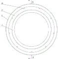
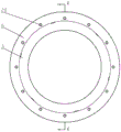
FIG. 2 is a front view of the bearing of the present invention employing an outer ring oil feed scheme;
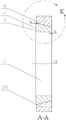
FIG. 3 isbase:Sub>A cross-sectional view A-A of FIG. 2;
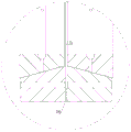
FIG. 4 is an enlarged view of a portion K of FIG. 3;
FIG. 5 is a side view of the bearing of the present invention utilizing an outer ring oil supply scheme;
fig. 6 is a partially enlarged view of portion L of fig. 5;
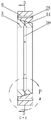
FIG. 7 is a cross-sectional view B-B of FIG. 5;
fig. 8 is a partial enlarged view of a portion M in fig. 7;
FIG. 9 is an isometric view of the inner race of the bearing employing the outer race oil feed arrangement of the present invention;
FIG. 10 is an elevational view of the inner race of the bearing of the present invention utilizing an outer race oil feed scheme;
fig. 11 is a partial enlarged view of a portion N in fig. 10;
FIG. 12 is a front view of a dual sump inner ring in accordance with an embodiment of the present invention;
FIG. 13 is an isometric view of a dual sump inner ring in accordance with an embodiment of the present invention;
FIG. 14 is a schematic view of the face-to-face assembly of the bearing of the present invention using an outer ring oil feed scheme;
FIG. 15 is a schematic view of a back-to-back assembly of the bearing of the present invention using an outer ring oil supply scheme;
FIG. 16 is an isometric view of a bearing employing the under-ring oil supply scheme of the present invention;
FIG. 17 is an elevation view of the bearing of the present invention employing an under-ring oil supply scheme;
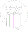
FIG. 18 is a cross-sectional view C-C of FIG. 17;
FIG. 19 is a cross-sectional view D-D of FIG. 18;
FIG. 20 is an enlarged partial view at P of FIG. 18;
FIG. 21 is an isometric view of the inner race of the bearing employing the under-ring oil supply arrangement of the present invention;
FIG. 22 is an elevational view of the inner race of the bearing of the present invention employing an under-the-ring oil supply arrangement;
fig. 23 is a partial enlarged view at Q in fig. 22;
FIG. 24 is a schematic view of a face-to-face assembly of the bearing of the present invention using an under-ring oil supply scheme;
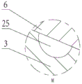
FIG. 25 is a schematic view of a back-to-back assembly of the bearing of the present invention using an under-ring oil supply scheme.
Reference numerals: 1. bearing inner bore, 2, inner ring inner chamfer, 3, bearing inner ring, 4, inner ring large end face, 5, inner ring outer chamfer, 6, bearing outer ring, 7, outer ring small end face, 8, outer ring outer chamfer, 9, seal ring groove outer chamfer, 10, seal ring groove bottom chamfer, 11, seal ring groove, 12, outer ring middle oil supply groove outer chamfer, 13, outer ring middle oil supply groove, 14, outer ring radial oil supply hole, 15, bearing outer wall, 16, outer ring large end face, 17, outer ring oil return groove, 18, outer ring radial oil supply hole chamfer, 19, sliding friction face, 20, inner ring small end face oil drain hole, 21, inner ring small end face, 22, bearing inner wall, 23, cone generatrix angle, 24, outer ring radial symmetry centerline, 25, curved oil drain section, 26, function curve oil drain groove, 27, inner ring large end face oil drain hole, 28, oil drain hole, 29, inner ring friction, 30, ring lower oil supply groove, 31, inner ring radial hole, 32, friction face chamfer, 33, oil supply hole, 34, spacer ring; alpha, conical included angle, O, bearing rotation center line.
Detailed Description
The technical solutions in the embodiments of the present invention will be clearly and completely described below with reference to the drawings in the embodiments of the present invention, and it is obvious that the described embodiments are only a part of the embodiments of the present invention, and not all of the embodiments. All other embodiments, which can be derived by a person skilled in the art from the embodiments given herein without making any creative effort, shall fall within the protection scope of the present invention.
Example 1: in this embodiment, a scheme of supplying oil to an outer ring is adopted, please refer to fig. 1 to 15, and a thin oil-lubricated one-way thrust tapered sliding bearing for supplying oil to an outer ring comprises a bearing outer ring 6 and a bearing inner ring 3 which are matched and sleeved, an outer circumferential surface of the bearing outer ring 6 is a bearing outer wall 15, an inner circumferential surface of the bearing inner ring 6 is a bearing inner wall 22, the bearing outer ring 6 and the bearing inner ring 3 are made of bearing steel, among several key parameters of the bearing, an outer diameter of the bearing is an outer diameter of the bearing outer wall 15, an inner diameter of the bearing is an inner diameter of the bearing inner wall 22, and a width of the bearing is a length of the bearing outer wall 15. The sliding friction surface 19 between the bearing outer ring 6 and the bearing inner ring 3 is conical, the sliding friction surface 19 specifically comprises an outer ring friction conical surface and an inner ring friction conical surface 29 which are in mutual contact, wherein the outer ring friction conical surface is a matching surface of the bearing outer ring 6 and the bearing inner ring 3, and the inner ring friction conical surface 29And the bearing inner ring 3 is matched with the bearing outer ring 6. The bearing outer ring 6 and the bearing inner ring 3 are in direct contact through the sliding friction surface 19, so that foreign matters can be effectively prevented from invading the friction surface without increasing a sealing piece, and the influence on the service life of the bearing due to the invasion of foreign matters is avoided. The inclination angle of the generatrix of the inner friction cone 29 depends on the axial and radial forces to be absorbed during the design The conditions are satisfied:
 correspondingly, the generatrix inclination angle of the outer ring friction cone and the generatrix inclination angle of the sliding
 friction surface 19 are both equal ,
, Is defined as the contact cone angle of the sliding bearing of the present invention. In order to achieve the standardization of the device,
 can be selected according to the relevant standard of the current angular contact bearing, and the A standard contact angle is 30
 degrees
30 degrees is selected, and the standard contact angle B is 40 degrees Selecting 40 degrees, and C standard contact angle is 15 degrees
 Selecting 15 degrees, and 25 degrees of standard contact angle of A5 (AC)
 Choose 25 degrees when
 The angle is 90 degrees, and the sliding bearing is a one-way thrust sliding bearing.
Structurally, the single-set bearing only comprises the bearing inner ring 3 and the bearing outer ring 6, the number of parts is small, the manufacturing and using cost is reduced, the accuracy of precision control in the manufacturing process and the interchangeability of the parts are improved, the assembly difficulty of the bearing is reduced, the type and the model of the bearing are greatly simplified, and the rotary vibration caused by defects or damages of rolling elements and a raceway during manufacturing and using can be effectively avoided due to the fact that the sliding bearing does not comprise the rolling elements. On the load capacity, the simple structure of the invention can greatly improve the axial and radial bearing capacity of the bearing and the structural rigidity of the bearing unit on the premise of completely meeting the function of the rolling bearing, is beneficial to improving the critical rotating speed of a rotary shaft system, and simultaneously has obviously improved impact load resistance compared with the rolling bearing. Compared with a rolling bearing, under the condition of the same load, the invention has smaller overall dimension, and is beneficial to the overall design layout of a rotary shaft system; because the bearing is always in conical surface contact, the vibration and noise generated by the bearing can be reduced to almost zero, so that the fatigue caused by the vibration of the bearing under the action of various loads in work can be ignored; under the action of the pre-tightening device, the bearing has the function of automatically compensating the abrasion of the friction conical surface, so that the consistency of the rotation precision of the whole life cycle of the bearing is ensured.
Solid super-lubrication coatings are arranged on the outer ring friction conical surface and the inner ring friction conical surface 29, and the solid super-lubrication coatings can be graphene coatings and the like. The inner ring friction conical surface 29 is provided with a function curve oil groove 26, the bearing outer wall 15 is provided with an outer ring middle oil supply groove 13 extending along the circumferential direction, the outer ring middle oil supply groove 13 is positioned in the middle of the bearing outer wall 15, namely the symmetrical center line of the outer ring middle oil supply groove 13 in the width direction is coplanar with the symmetrical center line 24 of the bearing outer wall 15, the section 25 of the curve oil groove of the outer ring middle oil supply groove 13 is U-shaped, rectangular or semicircular, and the outer ring middle oil supply groove 13 is used for providing a lubricating medium for the sliding bearing. The bearing outer ring 6 is further provided with a plurality of outer ring radial oil supply holes 14 extending along the radial direction, specifically, the outer ring radial oil supply holes 14 are formed in the bottom of the outer ring middle oil supply groove 13, the outer ring radial oil supply holes 14 are communicated with the outer ring middle oil supply groove 13 and penetrate through the outer ring friction conical surface, the number of the outer ring radial oil supply holes 14 is set to be an odd number in general, and the diameter and the number of the outer ring radial oil supply holes 14 are positively correlated with the diameter of the bearing, the width of the bearing, the viscosity of a lubricating medium and the design application rotating speed. In practical application, the bearing outer ring 6 is installed in the bearing seat hole, the bearing outer ring middle oil supply groove 13 is opposite to an oil hole for supplying lubricating medium to the bearing seat, the lubricating medium enters the outer ring middle oil supply groove 13 from the bearing seat and flows in the outer ring middle oil supply groove 13, then flows towards the sliding friction surface 19 along the outer ring radial oil supply hole 14, when the oil outlet end of the outer ring radial oil supply hole 14 is communicated with the function curve oil groove 26 on the inner ring friction conical surface 29, the lubricating medium enters the function curve oil groove 26, accelerates to flow in the function curve oil groove 26 along with the rotation of the bearing inner ring 3, and forms an oil film distributed on the sliding friction surface 19 to lubricate the sliding friction surface 19, and takes away heat and abrasive dust on the sliding friction surface 19 along with the lubricating medium, so that double super-lubrication of the sliding friction surface 19 by the solid super-lubricating coating and super-lubricating medium is realized.
The linear shape of the function curve oil groove 26 is selected to facilitate the flow of the lubricating medium and the formation of the oil film on the sliding friction surface 19, and in the present invention, the center line of the function curve oil groove 26 is a closed sine function curve, and since the linear shapes of the sine function and the cosine function are the same, the center line of the function curve oil groove 26 can also be set to be a cosine function curve. The peak-to-peak value of the function curve is larger than or equal to the length of the generatrix of the inner ring friction conical surface 29, the section of the oil groove 26 of the function curve is U-shaped or rectangular, and the width and the depth of the oil groove 26 of the function curve are positively correlated with the length of the generatrix of the inner ring friction conical surface 29, the design load of the sliding bearing, the working speed and the viscosity of the lubricating medium. The peak-to-peak value of the function curve is greater than or equal to the length of the generatrix of the inner ring friction conical surface 29, so that the peak position and the trough position of the function curve oil groove 26 can penetrate through the large end surface 4 and the small end surface 21 of the end surface of the bearing inner ring 3, and an inner ring small end surface oil groove oil drainage hole 20 and an inner ring large end surface oil groove oil drainage hole 27 are formed respectively. The lubricating medium in the function curve oil groove 26 can flow out from the oil groove drainage hole 20 on the small end surface of the inner ring and the oil groove drainage hole 27 on the large end surface of the inner ring, so that the friction surface 19 is ensured, the grinding dust possibly generated on the sliding friction surface 19 is brought out, the abrasion of the friction matching surface is reduced, and the function of cooling the friction surface is also realized.
The flowing direction of the lubricating medium in the function curve oil groove 26 is related to the rotating direction of the bearing inner ring 3, for example, when the bearing inner ring 3 rotates in the Z direction shown in fig. 10, the flowing route of the lubricating medium in the function curve oil groove 26 is shown as U, V, X, Y in fig. 11, the W position on the function curve oil groove 26 in fig. 11 represents a position corresponding to the outer ring radial oil supply hole 14, the lubricating medium and air mixture flowing in the function curve oil groove 26 in the direction shown by the U arrow is discharged from the inner ring large end surface oil drain hole 27, the function curve oil groove 26 sucks air from the inner ring large end surface oil drain hole 27 in the direction shown by the V arrow, and after the W position is mixed with the lubricating medium coming from the outer ring radial oil supply groove 14, the lubricating medium is discharged from the inner ring small end surface oil drain hole 20 in the direction shown by the X arrow, the function curve oil groove 26 sucks air from the inner ring small end surface oil drain hole 20 in the direction shown by the Y arrow, and then the flowing process in the U direction flows in the function curve oil groove 26, finally forming a circulation. Because the outer ring friction conical surface and the inner ring friction conical surface 29 are completely attached, the mixture of the lubricating medium and the air plays roles of lubricating the friction conical surface, cooling the friction conical surface and flushing abrasive dust in the flowing process. In the present invention, the lubricating medium is a lubricating oil having super-lubricating properties. The ultra-smooth sliding bearing is implemented based on the combination of the liquid ultra-smooth technology and the solid coating ultra-smooth technology, so that the performance and the service life of the sliding bearing are greatly improved.
The periodicity of the function is related to the operating speed of the slide bearing, the lower the periodicity of the centre line of the oil groove 26 of the function. The number of cycles of the center line of the function curve oil groove 26 is set to ensure smooth flow of the lubricating medium in the function curve oil groove 26 and effective lubrication of the sliding friction surface 19Extracting; the decrease of the number of cycles of the center line of the function-curve oil groove 26 is advantageous for the flow of the lubricating medium but not advantageous for the maintenance of the lubricating oil film on the sliding friction face 19, and the increase of the number of cycles of the center line of the function-curve oil groove 26 is advantageous for the maintenance of the lubricating oil film on the sliding friction face 19 but not advantageous for the flow of the lubricating medium, depending on the bearing diameter, the operating speed, the contact cone angle, and the like The length of the contact conical surface, the load and the like are considered together. When a single function
 curve oil groove 26 cannot meet the lubrication requirement, such as a low-speed large-load bearing, in order to ensure the accelerated flow of a lubricating medium in the curve oil groove, when the curve period number is too small to meet the lubrication requirement normally required by a friction surface, a mode of enlarging the section of the function curve oil groove 26 or a mode of adopting two identical function curve oil grooves 26 can be adopted, the phase difference of the two identical function curve oil grooves is 1/2 period, namely 180 degrees, and the junction of the two curves is alternately communicated with the outer ring radial oil supply hole 14 in the rotation process of the sliding bearing.
Two sealing ring grooves 11 extending along the circumferential direction are further formed in the bearing outer wall 15, and the two sealing ring grooves 11 are located on two sides of the outer ring middle oil supply groove 13 respectively and are symmetrical about the outer ring middle oil supply groove 13. When needed, O-shaped sealing rings can be additionally arranged in the two sealing ring grooves 11, so that the lubricating medium is prevented from leaking from the middle oil supply groove 13 of the outer ring.
The smaller one of the two end faces of the bearing outer ring 6 is an outer ring small end face 7, the other end face is an outer ring large end face 16, the smaller one of the two end faces of the bearing inner ring 3 is an inner ring small end face 21, the other end face is an inner ring large end face 4, and end face gaps are reserved between the outer ring small end face 7 and the inner ring large end face 4 and between the outer ring large end face 16 and the inner ring small end face 21. The end face gap is used as the abrasion automatic compensation stroke of the sliding friction surface 19, and the width L of the end face gap 1 The component of the sum of the thickness of the solid super-lubrication coating on the inner ring friction conical surface 29 and the thickness of the solid super-lubrication coating on the outer ring friction conical surface in the axial direction of the sliding bearing is less than or equal to. When in useWhen the outer ring big end face 16 is adopted for positioning, the inner ring big end face 4 is a pre-tightening loading end face; when the inner ring large end face 4 is used for positioning, the outer ring large end face 16 is a pre-tightening loading end face. Because the lubricating medium is provided for the outer ring, the bearing outer ring 6 is static and the bearing inner ring 3 rotates during working, the large end surface 16 of the outer ring is used as a pre-tightening loading end surface during application; the pre-tightening mode can adopt constant pressure pre-tightening or positioning pre-tightening, so that the inner friction conical surface 29 and the outer friction conical surface are always in a completely inosculated state. Because the influence of the contact area and the positive pressure of the sliding friction surface 19 on the friction coefficient is extremely small in the super-lubrication state, the axial pretightening force needs to be properly increased in order to ensure the complete fit of the sliding friction surface 19 and the automatic compensation after the friction conical surface is abraded, if the solid super-lubrication coating is abraded, the bearing inner ring 3 and the bearing outer ring 6 move oppositely under the action of the axial pretightening force, and the width L of the end surface clearance 1 The friction conical surface 29 of the inner ring and the friction conical surface of the outer ring are continuously kept to be completely attached; the setting of conical surface contact plus axial pretightening force is adopted, so that the contact surface has an automatic compensation function within a normal abrasion range, failure of rotation precision of the bearing due to change of play in the installation and use processes is avoided, and the consistency of the rotation precision of the bearing within the whole life cycle is structurally ensured.
An outer ring oil return groove 17 is formed in the outer ring large end face 16, the outer ring oil return groove 17 is an annular groove and is coaxial with the outer ring, and the depth of the outer ring oil return groove 17 is larger than or equal to the width L of the end face gap 1 . After the sliding bearing is installed, the small end face 21 of the inner ring is attached to a shaft convex shoulder, the large end face 16 of the outer ring is attached to a positioning convex shoulder or an axial pre-tightening device of a bearing seat, and the end face clearance can ensure that a clearance is reserved between the rotating inner ring and the static non-rotating positioning convex shoulder or the axial pre-tightening device of the bearing seat, so that mutual contact cannot be generated, and meanwhile, the oil drainage hole 20 of the oil groove on the small end face of the inner ring is not shielded, and a channel is provided for discharging a lubricating medium. Therefore, the outer ring oil return groove 17 is formed in the outer ring large end face 16, so that the lubricating medium can enter the outer ring oil return groove 17 firstly and then be discharged smoothly. Specifically, the inner ring small end face 21 is flush with or lower than the bottom of the outer ring oil return groove 17. At this time, the end face is gappedWidth L 1 The maximum friction conical surface abrasion automatic compensation stroke is equal to the minimum oil return channel clearance and the maximum friction conical surface abrasion automatic compensation stroke which guarantee smooth oil return of the lubricating medium.
A plurality of outer ring oil drainage holes 28 are uniformly formed in the bearing outer ring 6, one end of each outer ring oil drainage hole 28 penetrates through the outer ring small end face 7, the other end of each outer ring oil drainage hole 28 penetrates through the bottom of the outer ring oil return groove 17, and lubricating media in the outer ring oil return groove 17 can flow between the outer ring small end face 7 and the outer ring large end face 16 along the outer ring oil drainage holes 28, so that the bearing can be guaranteed to be installed and assembled in any way, and a channel can be provided for the discharging and the backflow of the lubricating media.
An outer ring radial oil supply hole chamfer 18 is arranged at one end of the outer ring radial oil supply hole 14 penetrating through the outer ring friction conical surface, and the size of the outer ring radial oil supply hole chamfer 18 is 0.5 × 0.5 mm; outer ring outer chamfers 8 are arranged at the junction of the outer ring large end face 16 and the bearing outer wall 15 and the junction of the outer ring small end face 7 and the bearing outer wall 15, and the outer ring outer chamfers 8 are fillets with the radius of 0.6 mm; inner ring inner chamfers 2 are arranged at the junction of the inner ring large end surface 4 and the bearing inner wall 22 and at the junction of the inner ring small end surface 21 and the bearing inner wall 22, and the inner ring inner chamfers 2 are fillets with the radius of 0.6 mm; two junctions of two side walls of the sealing ring groove 11 and the bearing outer wall 15 are provided with sealing ring groove outer chamfers 9, and two junctions of two side walls and the bottom of the sealing ring groove 11 are provided with sealing ring groove bottom chamfers 10; outer ring intermediate oil supply groove outer chamfers 12 are respectively arranged at two junctions of two side walls of the outer ring intermediate oil supply groove 13 and the bearing outer wall 15. The chamfering device has the advantages that the chamfering device is convenient to mount and can prevent parts from being scratched, the size of the chamfering device can meet the requirements of most size bearings, and if the chamfering device is under special conditions such as ultra-large bearings, the size of the chamfering device can be adjusted according to actual requirements.
In actual installation, the invention can adopt single installation, back-to-back installation of two sliding bearings or face-to-face installation of two sliding bearings, and also can adopt the combination of more than two bearings. The bearing inner hole 1 is arranged on the diameter of the rotary shaft. When two sliding bearings are arranged back to back, the large end faces 4 of the inner rings of the two sliding bearings are attached to each other, and the small ends of the outer rings of the two sliding bearings are attached to each otherFace-to-face assembly gaps are left between the faces 7, and the width of the gaps is L 2 (ii) a When two sliding bearings are installed face to face, the large end faces 16 of the outer rings of the two sliding bearings are attached to each other, and a back-to-back assembly gap with the width of L is reserved between the small end faces 21 of the inner rings of the two sliding bearings 3 And has L 3 =L 2 =2×L 1 . When more than two bearings are assembled and installed, the oil drainage holes 28 of the outer rings are ensured to be aligned so as to reduce the flowing resistance of a lubricating medium.
Example 2: in this embodiment, a scheme of oil supply under the ring is adopted, please refer to fig. 16 to 25, and this embodiment provides a one-way thrust conical sliding bearing lubricated by thin oil supplied under the ring, and compared with the oil supply of the outer ring in embodiment 1, the present embodiment has different oil supply positions of the lubricating oil, which brings about a corresponding structural change.
The utility model provides a lubricated one-way thrust conical sliding bearing of oil feed thin oil under ring, is including the bearing inner race 3 and the bearing outer lane 6 of cooperation suit, and the outer peripheral face of bearing outer lane 6 is bearing outer wall 15, and the bearing hole has been seted up to the center department of bearing inner race 3, and the inner wall of bearing hole is bearing inner wall 22. The sliding friction surface 19 between the bearing inner ring 3 and the bearing outer ring 6 is a conical surface, and specifically the sliding friction surface 19 includes an outer ring friction conical surface and an inner ring friction conical surface, wherein the outer ring friction conical surface is a surface on the bearing outer ring 6, which is matched with the bearing inner ring 3, and the inner ring friction conical surface is a surface on the bearing inner ring 3, which is matched with the bearing outer ring 6. Compared with a rolling bearing, the bearing outer ring 6 is in direct contact with the bearing inner ring 3, so that foreign matters can be effectively prevented from invading a friction surface without increasing a sealing piece, and the influence on the service life of the bearing due to the invasion of foreign matters is avoided. The bus inclination angle of the outer friction conical surface is equal to the bus inclination angle of the inner friction conical surface and is recorded as According to the axial force and the radial force which need to be born by the sliding bearing during design,
 satisfy the condition
 。
。
And the inner ring friction conical surface and the outer ring friction conical surface are both provided with solid super-lubricating coatings. The inner friction conical surface is also provided with a function curve oil groove 26. The hole wall of the bearing inner hole is provided with a ring lower oil supply groove 30 extending along the circumferential direction, and the ring lower oil supply groove 30 is arranged in the middle of the bearing inner wall 22. The bearing inner ring 3 is further provided with a plurality of radially extending inner ring radial oil supply holes 31, one end of each inner ring radial oil supply hole 31 is communicated with the ring lower oil supply groove 30, and the other end of each inner ring radial oil supply hole 31 penetrates through the inner ring friction conical surface. The cross-section of the ring lower oil supply groove 30 is U-shaped or rectangular, but may be other shapes. The bore diameter of the inner ring radial oil supply hole 31 is in positive correlation with the length of a generatrix of the inner ring friction conical surface, the working rotating speed of the sliding bearing, the design load of the sliding bearing and the viscosity of lubricating oil.
When the transition sleeve is used, the transition sleeve is fixedly sleeved on the rotating shaft and synchronously rotates along with the rotating shaft, an oil supply way is arranged on the transition sleeve, and then the sliding bearing is arranged on the transition sleeve. When the bearing works, the transition sleeve drives the bearing inner ring 3 to rotate, meanwhile, lubricating oil enters the oil supply groove 30 under the ring through an oil supply channel on the transition sleeve, and under the centrifugal action, the lubricating oil flows and is uniformly distributed in the oil supply groove 30 under the ring. Then, the lubricating oil flows toward the inner ring frictional tapered surface through the inner ring radial oil supply hole 31, and when the lubricating oil reaches the inner ring frictional tapered surface, an oil film is formed, thereby lubricating the sliding frictional surface 19. Meanwhile, along with the continuous rotation of the bearing inner ring 3, the inner ring radial oil supply hole 31 is communicated with the function curve oil groove 26, and lubricating oil can flow into the function curve oil groove 26, so that an oil film is more uniform and the oil quantity is abundant, and finally the under-ring lubrication of the sliding bearing is completed. According to the invention, the solid super-lubrication coating is matched with the under-ring lubrication, so that the super-lubrication between the bearing outer ring 6 and the bearing inner ring 3 is realized, and the performance and the service life of the sliding bearing are greatly improved.
The smaller end face of the bearing inner ring 3 is an inner ring small end face 21, the larger end face of the bearing inner ring 3 is an inner ring large end face 4, the smaller end face of the bearing outer ring 6 is an outer ring small end face 7, and the larger end face of the bearing outer ring 6 is a bearing outer ringThe large end face is the outer ring large end face 16, and end face gaps are reserved between the inner ring small end face 21 and the outer ring large end face 16 and between the inner ring large end face 4 and the outer ring small end face 7 in the axial direction of the sliding bearing. The width of the end face gap is L 1 The end surface clearance can ensure that a clearance is reserved between the rotating inner ring and the static non-rotating bearing seat positioning convex shoulder or the axial pre-tightening device, so that mutual contact cannot be generated, and meanwhile, the oil drain hole 20 of the oil groove on the small end surface of the inner ring is also ensured not to be shielded, so that a channel is provided for discharging lubricating oil.
In this embodiment, the shape and the setting mode of the function curve oil groove 26 are the same as those of embodiment 1, during the operation of the sliding bearing, the abrasion dust generated on the sliding friction surface 19 can be adhered by the lubricating oil in the function curve oil groove 26 and flows along with the lubricating oil in the function curve oil groove 26, and is finally discharged from the oil drainage hole 20 of the inner ring small end surface oil groove and the oil drainage hole 27 of the inner ring large end surface oil groove, so that the abrasion dust is prevented from being retained on the sliding friction surface 19 to cause the abrasion and the heating of the solid super-lubricating coating, and the lubricating oil can also take away the heat generated by the friction between the bearing outer ring 6 and the bearing inner ring 3 when being discharged, thereby realizing the purpose of cooling, and ensuring the stable operation of the sliding bearing.
In this embodiment, the function curve oil groove 26 is further provided with a plurality of oil inlets 33, the oil inlets 33 are formed in the middle point of the part from the wave trough to the wave crest of the function curve oil groove 26, the oil inlets 33 are circular holes formed by forming two circular arc-shaped grooves in two side walls of the function curve oil groove 26, and therefore the aperture of the oil inlets 33 is larger than the width of the function curve oil groove 26. During the rotation of the bearing inner ring 3, the oil inlet hole 33 alternately cooperates with the inner ring radial oil supply hole 31 to communicate the ring lower oil supply groove 30 with the function curve oil groove 26, so that the lubricating oil in the ring lower lubrication groove 30 flows into the function curve oil groove 26 through the inner ring radial oil supply hole 31.
In the same manner as in embodiment 1, the bearing outer ring 6 of this embodiment is also provided with outer ring drain holes 28 having the same function.
The sliding bearing of the present embodiment may be used in two rows. The specific assembling mode comprises back-to-back assembling and face-to-face assembling.
In the face-to-face arrangement, the outer races 6 of the two bearings are formed with a width L due to the presence of the end face clearance, as shown in figure 24 2 Assembly gap of L 2 =2L 1 And the large inner ring end surfaces 4 of the bearing inner rings 3 of the two sliding bearings are in direct contact.
As shown in FIG. 25, in the back-to-back assembly, the inner ring small end surfaces 21 of the bearing inner rings 3 of the two sliding bearings are oppositely arranged, and the width L is additionally increased 3 Assembly gap of L 3 =2L 1 Since there are two end surface clearances, the total oil supply width between the two inner ring small end surfaces 21 is 4L 1 Then a spacer 34 is added between the two bearing outer rings 1, the width of the spacer 34 is 2L 1 And is a lubricating oil discharge passage.
It is further noted that, herein, relational terms such as first and second, and the like may be used solely to distinguish one entity or action from another entity or action without necessarily requiring or implying any actual such relationship or order between such entities or actions. Also, the terms "comprises," "comprising," or any other variation thereof, are intended to cover a non-exclusive inclusion, such that a process, method, article, or apparatus that comprises a list of elements does not include only those elements but may include other elements not expressly listed or inherent to such process, method, article, or apparatus. Without further limitation, an element defined by the phrase "comprising a … …" does not exclude the presence of another identical element in a process, method, article, or apparatus that comprises the element.
The previous disclosure of the embodiments is provided to enable any person skilled in the art to make or use the present invention. Various modifications to these embodiments will be readily apparent to those skilled in the art, and the generic principles defined herein may be applied to other embodiments without departing from the spirit or scope of the invention. Thus, the present invention is not intended to be limited to the embodiments shown herein but is to be accorded the widest scope consistent with the principles and novel features disclosed herein.
Claims (17)
1. The utility model provides a one-way thrust conical sliding bearing of thin oil lubrication, bearing inner race (3) including cooperation suit bearing inner race (6), the outer peripheral face of bearing inner race (6) is bearing outer wall (15), and the inner peripheral surface of bearing inner race is bearing inner wall, goes up in bearing inner race (6) and is outer lane friction conical surface with the fitting surface of bearing inner race (3), is inner circle friction conical surface (29) with the fitting surface of bearing inner race (6) on bearing inner race (3), its characterized in that:
the outer ring friction conical surface and the inner ring friction conical surface (29) are both provided with solid super-lubricating coatings, the inner ring friction conical surface (29) is provided with a function curve oil groove (26), the outer wall of the bearing or the inner wall of the bearing is provided with an oil supply groove extending along the circumferential direction, the outer ring of the bearing or the inner ring of the bearing is provided with a plurality of radial oil supply holes extending along the circumferential direction at intervals, one end of each radial oil supply hole is communicated with the oil supply groove, and the other end of each radial oil supply hole is opened on the outer ring friction conical surface or the inner ring friction conical surface and is communicated with the function curve oil groove (26); the wave crest and the wave trough of the function curve oil groove (26) respectively penetrate through the inner ring large end face (4) and the inner ring small end face (21) of the bearing inner ring (3), and then an inner ring large end face oil drainage hole (27) and an inner ring small end face oil drainage hole (20) are formed respectively.
2. A thin oil-lubricated one-way thrust conical sliding bearing as claimed in claim 1, wherein: the radial oil supply hole is formed in the bearing outer ring, the oil supply groove is an outer ring middle oil supply groove (13) formed in the bearing outer wall (15), and the radial oil supply hole is an outer ring radial oil supply hole (14) formed in the bearing outer ring (6).
3. A thin oil-lubricated one-way thrust conical sliding bearing as claimed in claim 2, wherein: two sealing ring grooves (11) extending along the circumferential direction are further formed in the bearing outer wall (15), and the two sealing ring grooves (11) are located on two sides of the outer ring middle oil supply groove (13) respectively.
4. A thin oil-lubricated one-way thrust conical sliding bearing as claimed in claim 2, wherein: the bearing is characterized in that a smaller end face of the bearing outer ring (6) is an outer ring small end face (7), the other end face is an outer ring big end face (16), a smaller end face of the bearing inner ring (3) is an inner ring small end face (21), the other end face is an inner ring big end face (4), and end face gaps are reserved between the outer ring small end face (7) and the inner ring big end face (4) and between the outer ring big end face (16) and the inner ring small end face (21) in the axial direction of the sliding bearing.
5. A thin oil-lubricated one-way thrust conical sliding bearing as claimed in claim 4, wherein: an outer ring oil return groove (17) is formed in the outer ring large end face (16), the outer ring oil return groove (17) is an annular groove and is coaxial with the bearing outer ring (6), and the depth of the outer ring oil return groove (17) is larger than or equal to the width of the end face gap.
6. A thin oil-lubricated one-way thrust conical sliding bearing as claimed in claim 2, wherein: the section of the outer ring middle oil supply groove (13) is U-shaped or rectangular.
7. A thin oil-lubricated one-way thrust conical sliding bearing as claimed in claim 1, wherein: the radial oil supply hole is formed in the bearing inner ring (3), the oil supply groove is a ring lower oil supply groove formed in the inner wall of the bearing, and the radial oil supply hole is an inner ring radial oil supply hole (31) formed in the bearing inner ring (3).
8. A thin oil-lubricated one-way thrust conical sliding bearing as claimed in claim 7, wherein: the cross section of the ring lower oil supply groove is U-shaped or rectangular.
9. A thin oil-lubricated one-way thrust conical sliding bearing as claimed in claim 7, wherein: the oil supply device is characterized in that the function curve oil groove (26) is further provided with a plurality of oil inlet holes (33), the diameter of each oil inlet hole (33) is larger than the width of the function curve oil groove (26), and the oil inlet holes (33) are alternately matched with the inner ring radial oil supply holes (31) to communicate the lower ring oil supply groove (30) with the function curve oil groove (26).
10. A thin oil-lubricated one-way thrust conical sliding bearing as claimed in claim 2 or 7, wherein: the functional curve oil grooves (26) are arranged into one or more than one, the central line of any one functional curve oil groove (26) is a closed sine function curve, and the peak-to-peak value of the sine function curve is larger than or equal to the length of the generatrix of the inner friction conical surface (29).
11. A thin oil-lubricated one-way thrust conical sliding bearing as claimed in claim 10, wherein: still set up a plurality of outer lane draining hole (28) along circumferencial direction evenly distributed on bearing inner race (6), the one end in outer lane draining hole (28) link up outer lane little terminal surface (7), and the bottom of outer lane oil return recess (17) of the big terminal surface of outer lane is link up to the other one end in outer lane draining hole (28).
12. A thin oil-lubricated one-way thrust conical sliding bearing as claimed in claim 10, wherein: the wave crest and the wave trough of the function curve oil groove (26) respectively penetrate through the inner ring large end face (4) and the inner ring small end face (21) of the bearing inner ring (3), and then an inner ring large end face oil drainage hole (27) and an inner ring small end face oil drainage hole (20) are formed respectively.
13. A thin oil-lubricated one-way thrust conical sliding bearing as claimed in any one of claims 1, 2 and 7, wherein: the cross section of the function curve oil groove (26) is U-shaped or rectangular.
14. A thin oil-lubricated one-way thrust conical sliding bearing as claimed in any one of claims 1, 2 and 7, wherein: the lower the operating speed of the plain bearing, the lower the number of cycles of the centre line of the oil groove (26) of the function curve.
15. A thin oil-lubricated one-way thrust conical sliding bearing as claimed in any one of claims 1, 2 and 7, wherein: the width and the depth of the function curve oil grooves (26) and the number of the function curve oil grooves (26) are positively correlated with the length of a generatrix of the inner ring friction conical surface (29), the design load of the sliding bearing, the working rotating speed and the viscosity of a lubricating medium.
16. A thin oil-lubricated one-way thrust conical sliding bearing according to any one of claims 1, 2 and 7, wherein: the bus inclination angle of the inner ring friction conical surface (29) is equal to the bus inclination angle of the outer ring friction conical surface and is recorded as And the following conditions are satisfied:
 。
。
17. a thin oil-lubricated one-way thrust conical sliding bearing as claimed in claim 1, wherein: the aperture of the radial oil supply hole is positively correlated with the length of a bus of the inner ring friction conical surface (29), the working rotating speed of the sliding bearing, the design load of the sliding bearing and the viscosity of a lubricating medium.
Priority Applications (1)
| Application Number | Priority Date | Filing Date | Title |
|---|---|---|---|
| CN202110579175.2A CN113339405B (en) | 2021-05-26 | 2021-05-26 | Thin oil lubrication one-way thrust conical sliding bearing |
Applications Claiming Priority (1)
| Application Number | Priority Date | Filing Date | Title |
|---|---|---|---|
| CN202110579175.2A CN113339405B (en) | 2021-05-26 | 2021-05-26 | Thin oil lubrication one-way thrust conical sliding bearing |
Publications (2)
| Publication Number | Publication Date |
|---|---|
| CN113339405A CN113339405A (en) | 2021-09-03 |
| CN113339405B true CN113339405B (en) | 2023-03-14 |
Family
ID=77472226
Family Applications (1)
| Application Number | Title | Priority Date | Filing Date |
|---|---|---|---|
| CN202110579175.2A Active CN113339405B (en) | 2021-05-26 | 2021-05-26 | Thin oil lubrication one-way thrust conical sliding bearing |
Country Status (1)
| Country | Link |
|---|---|
| CN (1) | CN113339405B (en) |
Families Citing this family (1)
| Publication number | Priority date | Publication date | Assignee | Title |
|---|---|---|---|---|
| CN118391349B (en) * | 2024-06-28 | 2024-09-24 | 洛阳轴研科技有限公司 | Rolling sliding composite bearing |
Citations (14)
| Publication number | Priority date | Publication date | Assignee | Title |
|---|---|---|---|---|
| JPH1151042A (en) * | 1997-08-05 | 1999-02-23 | Seiko Instr Inc | Dynamic pressure bearing, spindle motor incorporating this bearing, and rotor device incorporating this spindle motor |
| JP2001027226A (en) * | 1999-07-12 | 2001-01-30 | Seiko Instruments Inc | Conical hydrodynamic pressure bearing and spindle motor |
| CN2517902Y (en) * | 2001-11-14 | 2002-10-23 | 福建龙溪轴承股份有限公司 | Angular joint bearing |
| JP2003269455A (en) * | 2002-03-18 | 2003-09-25 | Nsk Ltd | Slide bearing |
| JP2004232826A (en) * | 2003-01-31 | 2004-08-19 | Tohoku Ricoh Co Ltd | Dynamic pressure bearing and spindle motor |
| CN2821260Y (en) * | 2005-09-16 | 2006-09-27 | 太原重型机械集团有限公司 | Oil film bearing with net type oil groove conic sleeve |
| CN101153631A (en) * | 2006-09-25 | 2008-04-02 | 湖南大学 | Exterior-clearance throttle cavity internal-hole type scavenging hydrostatic bearing |
| JP2009287590A (en) * | 2008-05-27 | 2009-12-10 | Fuji Xerox Co Ltd | Bearing device and image forming device |
| CN201507551U (en) * | 2009-09-03 | 2010-06-16 | 洛阳市洛凌轴承科技股份有限公司 | Hydrostatic bearing capable of bearing bidirectional load |
| JP2015127570A (en) * | 2013-12-27 | 2015-07-09 | 三菱重工業株式会社 | Bearing device and grinding device |
| CN105626693A (en) * | 2015-05-05 | 2016-06-01 | 中信重工机械股份有限公司 | Spiral groove radial sliding bearing lubricated by grease |
| CN108468715A (en) * | 2018-05-18 | 2018-08-31 | 深圳超磁机器人科技有限公司 | A kind of ultra-thin oilless bearing |
| CN207945202U (en) * | 2018-02-09 | 2018-10-09 | 瓦房店欧德轴承制造有限公司 | Cylinder roller bearing |
| JP6832998B1 (en) * | 2019-09-06 | 2021-02-24 | 株式会社牧野フライス製作所 | Rotary work head using sliding circular motion guide device and sliding circular motion guide device |
Family Cites Families (4)
| Publication number | Priority date | Publication date | Assignee | Title |
|---|---|---|---|---|
| JPH06109024A (en) * | 1992-09-29 | 1994-04-19 | Hitachi Medical Corp | Manufacture of solid lubrication type rolling bearing |
| JPH0742729A (en) * | 1993-07-30 | 1995-02-10 | Ntn Corp | Spherical sliding bearing |
| US9140302B2 (en) * | 2013-06-13 | 2015-09-22 | The Boeing Company | Joint bearing lubricant system |
| CN105275980A (en) * | 2015-10-22 | 2016-01-27 | 南通美利华机电有限公司 | Conical roller bearing |
-
2021
- 2021-05-26 CN CN202110579175.2A patent/CN113339405B/en active Active
Patent Citations (14)
| Publication number | Priority date | Publication date | Assignee | Title |
|---|---|---|---|---|
| JPH1151042A (en) * | 1997-08-05 | 1999-02-23 | Seiko Instr Inc | Dynamic pressure bearing, spindle motor incorporating this bearing, and rotor device incorporating this spindle motor |
| JP2001027226A (en) * | 1999-07-12 | 2001-01-30 | Seiko Instruments Inc | Conical hydrodynamic pressure bearing and spindle motor |
| CN2517902Y (en) * | 2001-11-14 | 2002-10-23 | 福建龙溪轴承股份有限公司 | Angular joint bearing |
| JP2003269455A (en) * | 2002-03-18 | 2003-09-25 | Nsk Ltd | Slide bearing |
| JP2004232826A (en) * | 2003-01-31 | 2004-08-19 | Tohoku Ricoh Co Ltd | Dynamic pressure bearing and spindle motor |
| CN2821260Y (en) * | 2005-09-16 | 2006-09-27 | 太原重型机械集团有限公司 | Oil film bearing with net type oil groove conic sleeve |
| CN101153631A (en) * | 2006-09-25 | 2008-04-02 | 湖南大学 | Exterior-clearance throttle cavity internal-hole type scavenging hydrostatic bearing |
| JP2009287590A (en) * | 2008-05-27 | 2009-12-10 | Fuji Xerox Co Ltd | Bearing device and image forming device |
| CN201507551U (en) * | 2009-09-03 | 2010-06-16 | 洛阳市洛凌轴承科技股份有限公司 | Hydrostatic bearing capable of bearing bidirectional load |
| JP2015127570A (en) * | 2013-12-27 | 2015-07-09 | 三菱重工業株式会社 | Bearing device and grinding device |
| CN105626693A (en) * | 2015-05-05 | 2016-06-01 | 中信重工机械股份有限公司 | Spiral groove radial sliding bearing lubricated by grease |
| CN207945202U (en) * | 2018-02-09 | 2018-10-09 | 瓦房店欧德轴承制造有限公司 | Cylinder roller bearing |
| CN108468715A (en) * | 2018-05-18 | 2018-08-31 | 深圳超磁机器人科技有限公司 | A kind of ultra-thin oilless bearing |
| JP6832998B1 (en) * | 2019-09-06 | 2021-02-24 | 株式会社牧野フライス製作所 | Rotary work head using sliding circular motion guide device and sliding circular motion guide device |
Also Published As
| Publication number | Publication date |
|---|---|
| CN113339405A (en) | 2021-09-03 |
Similar Documents
| Publication | Publication Date | Title |
|---|---|---|
| US2219031A (en) | Bearing construction | |
| CN113339405B (en) | Thin oil lubrication one-way thrust conical sliding bearing | |
| CN113339403B (en) | Grease lubrication bidirectional thrust conical sliding bearing | |
| CN118224188A (en) | Self-lubricating cooled high-speed bearing | |
| CN110259830A (en) | A kind of raceway face has the ball bearing and its lubricating method of micro- texture | |
| US1961029A (en) | Self-cooling high pressure lubricant film bearing | |
| JPH09151946A (en) | Roller bearing | |
| US20030156769A1 (en) | Fluid suspended bearing | |
| CN201723572U (en) | Thrust bearing structure with oil slinger | |
| CN215762795U (en) | Heavy-load slewing bearing device with check ring for high-precision rotary table | |
| CN113339404B (en) | Grease lubrication one-way thrust conical sliding bearing | |
| US3301615A (en) | Rolling bearings | |
| CN212803705U (en) | Grease lubrication bearing structure of centrifugal pump | |
| JP4089209B2 (en) | Double suction centrifugal pump | |
| CN213474519U (en) | Full-effect sealed energy-saving mute carrier roller | |
| RU62183U1 (en) | BEARING-BEARING WITH COMBINED FRICTION COUPLE (OPTIONS) | |
| CN203926386U (en) | A kind of high-mechanic selflubricating flange bearing | |
| JP2002303297A (en) | Horizontal shaft type pump | |
| CN105673547B (en) | A kind of water lubricating thrust bearing possessing component | |
| US20240093733A1 (en) | Rolling bearing with fully-filled plastic oil and manufacturing method therefor | |
| CN206972599U (en) | A kind of thrust bearing for magnetic pumps structure and magnetic drive pump | |
| CN113339406B (en) | Bidirectional thrust conical sliding bearing | |
| CN209539818U (en) | A kind of driven compressor axle bearing | |
| CN214118753U (en) | Sliding bearing suitable for working under heavy load condition | |
| CN206988408U (en) | A kind of sliding bearing of tandem rolling tube machine high-speed shaft of speed reducer |
Legal Events
| Date | Code | Title | Description |
|---|---|---|---|
| PB01 | Publication | ||
| PB01 | Publication | ||
| SE01 | Entry into force of request for substantive examination | ||
| SE01 | Entry into force of request for substantive examination | ||
| GR01 | Patent grant | ||
| GR01 | Patent grant |