CN113304591A - Method and system for purifying flue gas of carbon roasting furnace - Google Patents
Method and system for purifying flue gas of carbon roasting furnace Download PDFInfo
- Publication number
- CN113304591A CN113304591A CN202110561608.1A CN202110561608A CN113304591A CN 113304591 A CN113304591 A CN 113304591A CN 202110561608 A CN202110561608 A CN 202110561608A CN 113304591 A CN113304591 A CN 113304591A
- Authority
- CN
- China
- Prior art keywords
- flue gas
- unit
- tar
- roasting furnace
- denitration
- Prior art date
- Legal status (The legal status is an assumption and is not a legal conclusion. Google has not performed a legal analysis and makes no representation as to the accuracy of the status listed.)
- Pending
Links
- 239000003546 flue gas Substances 0.000 title claims abstract description 134
- UGFAIRIUMAVXCW-UHFFFAOYSA-N Carbon monoxide Chemical compound [O+]#[C-] UGFAIRIUMAVXCW-UHFFFAOYSA-N 0.000 title claims abstract description 133
- OKTJSMMVPCPJKN-UHFFFAOYSA-N Carbon Chemical compound [C] OKTJSMMVPCPJKN-UHFFFAOYSA-N 0.000 title claims abstract description 45
- 229910052799 carbon Inorganic materials 0.000 title claims abstract description 45
- 238000000034 method Methods 0.000 title claims abstract description 41
- MWUXSHHQAYIFBG-UHFFFAOYSA-N nitrogen oxide Inorganic materials O=[N] MWUXSHHQAYIFBG-UHFFFAOYSA-N 0.000 claims abstract description 90
- 238000001816 cooling Methods 0.000 claims abstract description 51
- 238000006477 desulfuration reaction Methods 0.000 claims abstract description 48
- 239000000428 dust Substances 0.000 claims abstract description 48
- 230000023556 desulfurization Effects 0.000 claims abstract description 47
- RAHZWNYVWXNFOC-UHFFFAOYSA-N Sulphur dioxide Chemical compound O=S=O RAHZWNYVWXNFOC-UHFFFAOYSA-N 0.000 claims abstract description 34
- 239000012716 precipitator Substances 0.000 claims abstract description 25
- 238000000746 purification Methods 0.000 claims abstract description 22
- 239000003795 chemical substances by application Substances 0.000 claims abstract description 19
- 239000000843 powder Substances 0.000 claims abstract description 17
- 239000010440 gypsum Substances 0.000 claims description 14
- 229910052602 gypsum Inorganic materials 0.000 claims description 14
- 238000005507 spraying Methods 0.000 claims description 8
- 238000005373 pervaporation Methods 0.000 claims description 7
- 238000001556 precipitation Methods 0.000 claims description 5
- 230000009467 reduction Effects 0.000 claims description 5
- XLYOFNOQVPJJNP-UHFFFAOYSA-N water Substances O XLYOFNOQVPJJNP-UHFFFAOYSA-N 0.000 abstract description 19
- 239000007921 spray Substances 0.000 abstract description 11
- 239000003344 environmental pollutant Substances 0.000 abstract description 10
- 231100000719 pollutant Toxicity 0.000 abstract description 10
- 239000011269 tar Substances 0.000 abstract description 3
- 238000002347 injection Methods 0.000 abstract 1
- 239000007924 injection Substances 0.000 abstract 1
- 239000000779 smoke Substances 0.000 description 31
- 239000010426 asphalt Substances 0.000 description 8
- 239000007789 gas Substances 0.000 description 6
- 238000004519 manufacturing process Methods 0.000 description 5
- 230000009471 action Effects 0.000 description 4
- 230000007613 environmental effect Effects 0.000 description 4
- 150000002500 ions Chemical class 0.000 description 4
- 239000003595 mist Substances 0.000 description 4
- 239000002245 particle Substances 0.000 description 4
- 230000008859 change Effects 0.000 description 3
- 239000000498 cooling water Substances 0.000 description 3
- 230000003009 desulfurizing effect Effects 0.000 description 3
- 238000005516 engineering process Methods 0.000 description 3
- 239000008187 granular material Substances 0.000 description 3
- 230000004048 modification Effects 0.000 description 3
- 238000012986 modification Methods 0.000 description 3
- 230000008569 process Effects 0.000 description 3
- 239000000047 product Substances 0.000 description 3
- 239000002002 slurry Substances 0.000 description 3
- 235000019738 Limestone Nutrition 0.000 description 2
- 239000002250 absorbent Substances 0.000 description 2
- 230000002745 absorbent Effects 0.000 description 2
- 230000006978 adaptation Effects 0.000 description 2
- XAGFODPZIPBFFR-UHFFFAOYSA-N aluminium Chemical compound [Al] XAGFODPZIPBFFR-UHFFFAOYSA-N 0.000 description 2
- 229910052782 aluminium Inorganic materials 0.000 description 2
- OSGAYBCDTDRGGQ-UHFFFAOYSA-L calcium sulfate Chemical compound [Ca+2].[O-]S([O-])(=O)=O OSGAYBCDTDRGGQ-UHFFFAOYSA-L 0.000 description 2
- 238000004140 cleaning Methods 0.000 description 2
- 238000005235 decoking Methods 0.000 description 2
- 238000000354 decomposition reaction Methods 0.000 description 2
- 238000009413 insulation Methods 0.000 description 2
- 239000006028 limestone Substances 0.000 description 2
- 239000007788 liquid Substances 0.000 description 2
- VNWKTOKETHGBQD-UHFFFAOYSA-N methane Chemical compound C VNWKTOKETHGBQD-UHFFFAOYSA-N 0.000 description 2
- 238000006722 reduction reaction Methods 0.000 description 2
- 239000000725 suspension Substances 0.000 description 2
- 239000004215 Carbon black (E152) Substances 0.000 description 1
- 235000008733 Citrus aurantifolia Nutrition 0.000 description 1
- 229910000831 Steel Inorganic materials 0.000 description 1
- 235000011941 Tilia x europaea Nutrition 0.000 description 1
- 239000000443 aerosol Substances 0.000 description 1
- 230000009286 beneficial effect Effects 0.000 description 1
- 238000007664 blowing Methods 0.000 description 1
- 239000006227 byproduct Substances 0.000 description 1
- GBAOBIBJACZTNA-UHFFFAOYSA-L calcium sulfite Chemical compound [Ca+2].[O-]S([O-])=O GBAOBIBJACZTNA-UHFFFAOYSA-L 0.000 description 1
- 235000010261 calcium sulphite Nutrition 0.000 description 1
- 238000010531 catalytic reduction reaction Methods 0.000 description 1
- 238000006243 chemical reaction Methods 0.000 description 1
- 239000013078 crystal Substances 0.000 description 1
- 230000007547 defect Effects 0.000 description 1
- 238000007791 dehumidification Methods 0.000 description 1
- 230000000694 effects Effects 0.000 description 1
- 230000005684 electric field Effects 0.000 description 1
- 239000010419 fine particle Substances 0.000 description 1
- 239000000446 fuel Substances 0.000 description 1
- 229930195733 hydrocarbon Natural products 0.000 description 1
- 150000002430 hydrocarbons Chemical class 0.000 description 1
- 239000002440 industrial waste Substances 0.000 description 1
- 230000005764 inhibitory process Effects 0.000 description 1
- 239000004571 lime Substances 0.000 description 1
- 238000012423 maintenance Methods 0.000 description 1
- 239000000463 material Substances 0.000 description 1
- 239000003345 natural gas Substances 0.000 description 1
- 230000003647 oxidation Effects 0.000 description 1
- 238000007254 oxidation reaction Methods 0.000 description 1
- 239000013618 particulate matter Substances 0.000 description 1
- 230000001681 protective effect Effects 0.000 description 1
- 239000002994 raw material Substances 0.000 description 1
- 229920006395 saturated elastomer Polymers 0.000 description 1
- 239000007787 solid Substances 0.000 description 1
- 239000010959 steel Substances 0.000 description 1
- 238000006467 substitution reaction Methods 0.000 description 1
- 238000005406 washing Methods 0.000 description 1
- 239000003643 water by type Substances 0.000 description 1
- 239000012719 wet electrostatic precipitator Substances 0.000 description 1
Images


Classifications
-
- B—PERFORMING OPERATIONS; TRANSPORTING
- B01—PHYSICAL OR CHEMICAL PROCESSES OR APPARATUS IN GENERAL
- B01D—SEPARATION
- B01D53/00—Separation of gases or vapours; Recovering vapours of volatile solvents from gases; Chemical or biological purification of waste gases, e.g. engine exhaust gases, smoke, fumes, flue gases, aerosols
- B01D53/34—Chemical or biological purification of waste gases
- B01D53/74—General processes for purification of waste gases; Apparatus or devices specially adapted therefor
- B01D53/75—Multi-step processes
-
- B—PERFORMING OPERATIONS; TRANSPORTING
- B01—PHYSICAL OR CHEMICAL PROCESSES OR APPARATUS IN GENERAL
- B01D—SEPARATION
- B01D53/00—Separation of gases or vapours; Recovering vapours of volatile solvents from gases; Chemical or biological purification of waste gases, e.g. engine exhaust gases, smoke, fumes, flue gases, aerosols
- B01D53/34—Chemical or biological purification of waste gases
- B01D53/46—Removing components of defined structure
- B01D53/48—Sulfur compounds
- B01D53/50—Sulfur oxides
- B01D53/501—Sulfur oxides by treating the gases with a solution or a suspension of an alkali or earth-alkali or ammonium compound
- B01D53/502—Sulfur oxides by treating the gases with a solution or a suspension of an alkali or earth-alkali or ammonium compound characterised by a specific solution or suspension
-
- B—PERFORMING OPERATIONS; TRANSPORTING
- B01—PHYSICAL OR CHEMICAL PROCESSES OR APPARATUS IN GENERAL
- B01D—SEPARATION
- B01D53/00—Separation of gases or vapours; Recovering vapours of volatile solvents from gases; Chemical or biological purification of waste gases, e.g. engine exhaust gases, smoke, fumes, flue gases, aerosols
- B01D53/34—Chemical or biological purification of waste gases
- B01D53/46—Removing components of defined structure
- B01D53/54—Nitrogen compounds
- B01D53/56—Nitrogen oxides
-
- B—PERFORMING OPERATIONS; TRANSPORTING
- B01—PHYSICAL OR CHEMICAL PROCESSES OR APPARATUS IN GENERAL
- B01D—SEPARATION
- B01D53/00—Separation of gases or vapours; Recovering vapours of volatile solvents from gases; Chemical or biological purification of waste gases, e.g. engine exhaust gases, smoke, fumes, flue gases, aerosols
- B01D53/34—Chemical or biological purification of waste gases
- B01D53/74—General processes for purification of waste gases; Apparatus or devices specially adapted therefor
- B01D53/80—Semi-solid phase processes, i.e. by using slurries
-
- B—PERFORMING OPERATIONS; TRANSPORTING
- B01—PHYSICAL OR CHEMICAL PROCESSES OR APPARATUS IN GENERAL
- B01D—SEPARATION
- B01D53/00—Separation of gases or vapours; Recovering vapours of volatile solvents from gases; Chemical or biological purification of waste gases, e.g. engine exhaust gases, smoke, fumes, flue gases, aerosols
- B01D53/34—Chemical or biological purification of waste gases
- B01D53/74—General processes for purification of waste gases; Apparatus or devices specially adapted therefor
- B01D53/81—Solid phase processes
- B01D53/83—Solid phase processes with moving reactants
-
- B—PERFORMING OPERATIONS; TRANSPORTING
- B03—SEPARATION OF SOLID MATERIALS USING LIQUIDS OR USING PNEUMATIC TABLES OR JIGS; MAGNETIC OR ELECTROSTATIC SEPARATION OF SOLID MATERIALS FROM SOLID MATERIALS OR FLUIDS; SEPARATION BY HIGH-VOLTAGE ELECTRIC FIELDS
- B03C—MAGNETIC OR ELECTROSTATIC SEPARATION OF SOLID MATERIALS FROM SOLID MATERIALS OR FLUIDS; SEPARATION BY HIGH-VOLTAGE ELECTRIC FIELDS
- B03C3/00—Separating dispersed particles from gases or vapour, e.g. air, by electrostatic effect
- B03C3/017—Combinations of electrostatic separation with other processes, not otherwise provided for
-
- F—MECHANICAL ENGINEERING; LIGHTING; HEATING; WEAPONS; BLASTING
- F27—FURNACES; KILNS; OVENS; RETORTS
- F27D—DETAILS OR ACCESSORIES OF FURNACES, KILNS, OVENS, OR RETORTS, IN SO FAR AS THEY ARE OF KINDS OCCURRING IN MORE THAN ONE KIND OF FURNACE
- F27D17/00—Arrangements for using waste heat; Arrangements for using, or disposing of, waste gases
- F27D17/008—Arrangements for using waste heat; Arrangements for using, or disposing of, waste gases cleaning gases
-
- B—PERFORMING OPERATIONS; TRANSPORTING
- B01—PHYSICAL OR CHEMICAL PROCESSES OR APPARATUS IN GENERAL
- B01D—SEPARATION
- B01D2251/00—Reactants
- B01D2251/40—Alkaline earth metal or magnesium compounds
- B01D2251/404—Alkaline earth metal or magnesium compounds of calcium
-
- B—PERFORMING OPERATIONS; TRANSPORTING
- B01—PHYSICAL OR CHEMICAL PROCESSES OR APPARATUS IN GENERAL
- B01D—SEPARATION
- B01D2251/00—Reactants
- B01D2251/60—Inorganic bases or salts
- B01D2251/606—Carbonates
-
- B—PERFORMING OPERATIONS; TRANSPORTING
- B01—PHYSICAL OR CHEMICAL PROCESSES OR APPARATUS IN GENERAL
- B01D—SEPARATION
- B01D2258/00—Sources of waste gases
- B01D2258/02—Other waste gases
- B01D2258/0283—Flue gases
Landscapes
- Engineering & Computer Science (AREA)
- Environmental & Geological Engineering (AREA)
- Chemical & Material Sciences (AREA)
- Health & Medical Sciences (AREA)
- Biomedical Technology (AREA)
- Analytical Chemistry (AREA)
- General Chemical & Material Sciences (AREA)
- Oil, Petroleum & Natural Gas (AREA)
- Chemical Kinetics & Catalysis (AREA)
- Mechanical Engineering (AREA)
- General Engineering & Computer Science (AREA)
- Treating Waste Gases (AREA)
Abstract
The invention discloses a method and a system for purifying flue gas of a carbon roasting furnace. The method for purifying the flue gas of the carbon roasting furnace comprises the steps of denitration, cooling, tar removal, desulfuration and demisting, dust removal and the like. The denitration adopts a method of direct injection of dry powder denitration agent, the cooling adopts a method of water spray, the tar removal adopts an electric tar precipitator, and the desulfurization adopts wet desulfurization. The carbon roasting furnace flue gas purification system comprises a denitration unit, a cooling unit, a tar removal unit, a desulfurization and demisting unit and a dust removal unit. By adopting the method and the system, pollutants such as nitrogen oxides, tar, sulfur dioxide, fog drops, dust and the like in the flue gas of the carbon roasting furnace can be removed to be below the emission limit value, and the method and the system are simple and practical, high in efficiency and low in operation cost.
Description
Technical Field
The invention relates to an industrial waste gas purification treatment technology, in particular to a carbon roasting furnace flue gas purification method and a system thereof.
Background
The carbon roasting production process usually uses natural gas as fuel to produce a large amount of flue gas containing nitrogen oxides, tar and SO2And dust and the like. At present, the domestic carbon roasting furnace flue gas treatment only comprises cooling spray towers (lime addition for desulfurization), vertical honeycomb type electric tar precipitator treatment and simple tar and desulfurization measures. According to the requirements of GB25465-2010 aluminum industry pollutant emission standard on modifying the smoke emission of production enterprises, the purified smoke particles are not higher than 10mg/m3、SO2Not higher than 100mg/m3,NOXNot higher than 100mg/m3Asphalt smoke is not higher than 20mg/m3. The pollutant concentration in the flue gas obtained by the existing flue gas treatment process can not meet the requirement of special emission limit value. With the increasingly strict national environmental protection policy, in order to reach increasingly strict emission standards and avoid the further stricter subsequent environmental protection policy, the carbon roasting flue gas treatment system must be modified in an environmental protection manner, and the carbon roasting flue gas treatment system is modified once to meet the ultra-low emission requirement, namely: the particulate matter is not higher than 5mg/m3、SO2Not higher than 35mg/m3,NOXNot higher than 50mg/m3The whole purification process requirement of the carbon roasting smoke is urgent. Therefore, it is necessary to develop a method and a system for purifying flue gas of a carbon roasting furnace, especially removing nitrogen oxides in the flue gas, and achieving higher tar and sulfur dioxide removal rate.
Disclosure of Invention
Aiming at the defects of the prior art, the invention aims to provide a carbon roasting furnace flue gas purification method and a system thereof, which can remove pollutants such as nitrogen oxide, tar, sulfur dioxide, fog drops, dust and the like in the carbon roasting furnace flue gas to be below the emission limit value, are simple and practical, and have high efficiency and low operation cost.
In order to achieve the purpose, the invention adopts the following technical scheme:
in a first aspect, the invention provides a method for purifying flue gas of a carbon roasting furnace, which comprises the following steps:
step 1) denitration: spraying the dry powder denitration agent into the position of a proper temperature point in a flue of the roasting furnace, so that the dry powder denitration agent reacts with nitric oxide in the flue gas to obtain flue gas from which the nitric oxide is removed;
step 2), cooling: introducing the obtained flue gas subjected to nitrogen oxide removal into a cooling device, and reducing the temperature of the flue gas to a proper temperature;
step 3) tar removal: the cooled flue gas enters an electric tar precipitator to remove tar;
step 4), desulfurization and demisting: removing sulfur dioxide in the flue gas by a limestone-gypsum wet desulphurization method, and then introducing the flue gas into a demister to remove fog drops;
step 5) dust removal: and removing the particulate matters in the flue gas by adopting a wet electric precipitation method.
Preferably, the proper temperature point in the step 1) refers to the position of the flue gas temperature of the roasting furnace flue of 950-1050 ℃.
Preferably, the suitable temperature range for said step 2) is 88-92 ℃.
Preferably, the voltage of the electrical tar precipitator in the step 3) adopts a high-voltage constant current source.
In a second aspect, the invention provides a carbon roasting furnace flue gas purification system, which comprises a denitration unit, a cooling unit, a tar removal unit, a desulfurization and demisting unit and a dust removal unit;
the denitration unit is connected with the cooling unit, the cooling unit is connected with the tar removing unit, the tar removing unit is connected with the desulfurization and demisting unit, and the desulfurization and demisting unit is connected with the dust removal unit.
Preferably, the denitration unit comprises a denitration frame and a pneumatic conveying device.
Preferably, the cooling unit comprises a cooling device, and the cooling device comprises a pervaporation cooling tower.
Preferably, the tar removing unit comprises an electrical tar precipitator which is of a honeycomb structure.
Preferably, the desulfurization and demisting unit comprises a limestone-gypsum wet desulfurization tower and a demister, the demister is arranged at the upper part of the limestone-gypsum wet desulfurization tower, and the demister comprises a plate demister.
Preferably, the dust removal unit comprises a wet electric dust removal device, and the wet electric dust removal device comprises a honeycomb tube type electric dust remover.
Compared with the prior art, the invention has the following beneficial effects: (1) by adopting the method and the system for purifying the flue gas of the carbon roasting furnace, the content of sulfur dioxide in the flue gas discharged outside the carbon roasting furnace can be lower than 35mg/Nm3The concentration of nitrogen oxide emission is lower than 50mg/Nm3Dust emission concentration is lower than 5mg/Nm3The emission concentration of the asphalt smoke is lower than 20mg/Nm3The requirement of the country on the environmental protection emission index of the industrial roasting furnace is further met; (2) the method and the system have the advantages of simplicity, practicability, high efficiency and low operation cost; (3) the system has the advantages of high running stability and reliability and can adapt to the change of working conditions.
Drawings
FIG. 1 is a schematic view of a method for purifying flue gas of a carbon baking furnace according to the present invention;
FIG. 2 is a schematic view of a flue gas purification system of a carbon baking furnace according to the present invention;
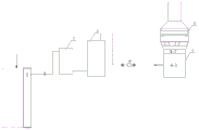
FIG. 3 is a schematic view of an embodiment of the flue gas cleaning system for a carbon baking furnace according to the present invention;
wherein:
1. the system comprises a denitration unit, a cooling unit, a tar removal unit, a desulfurization and demisting unit, a dust removal unit, 4-1, a limestone-gypsum wet desulfurization tower, 4-2 and a demister, wherein the denitration unit comprises 2 parts of a cooling unit, 3 parts of a tar removal unit, 4 parts of a desulfurization and demisting unit, 5 parts of a dust removal unit.
Detailed Description
The invention provides a method and a system for purifying carbon roasting furnace flue gas, which can remove pollutants such as nitrogen oxide, tar, sulfur dioxide, fog drops, dust and the like in the carbon roasting furnace flue gas to be below an emission limit value, and are simple, practical, high in efficiency and low in operation cost.
The invention provides a method for purifying flue gas of a carbon roasting furnace, which comprises the following steps as shown in figure 1:
step 1) denitration: spraying the dry powder denitration agent into the position of a proper temperature point in a flue of the roasting furnace, so that the dry powder denitration agent reacts with nitric oxide in the flue gas to obtain flue gas from which the nitric oxide is removed;
step 2), cooling: introducing the obtained flue gas subjected to nitrogen oxide removal into a cooling device, and reducing the temperature of the flue gas to a proper temperature;
step 3) tar removal: the cooled flue gas enters an electric tar precipitator to remove tar;
step 4), desulfurization and demisting: removing sulfur dioxide in the flue gas by a limestone-gypsum wet desulphurization method, and then introducing the flue gas into a demister to remove fog drops;
step 5) dust removal: and removing the particulate matters in the flue gas by adopting a wet electric precipitation method.
The denitration in the step 1) adopts an SNCR technology. The SNCR denitration technology of the roasting furnace sprays solid powdery reduction denitration agent (namely dry powder denitration agent) into a fire channel by using a pneumatic conveying device, and the denitration agent is completely pyrolyzed in a proper temperature area (950-1050 ℃) to generate organic decomposition products such as gaseous reduction hydrocarbon and the like, and the generated organic decomposition products and NO are mixedXCarrying out a selective catalytic reduction reaction to reduce NOx to N2、CO2And H2And O. The residual rate of the denitrifier is low, resistance is not increased in the denitration process, and the influence on the normal operation of the kiln is small.
Preferably, the proper temperature point in the step 1) refers to the position of the flue gas temperature of the roasting furnace flue of 950-1050 ℃.
Preferably, the denitration device adopts a pneumatic conveying device to spray the dry powder denitration agent into a proper temperature point (-950 ℃) position in the flue of the roasting furnace to react with NOx (nitrogen oxide) in the flue gas, so that the aim of removing the nitrogen oxide in the flue gas is fulfilled, the temperature of the roasted flue gas after denitration is reduced, and the temperature of the flue gas after denitration can be reduced to 120-200 ℃ in general conditions, and then the flue gas enters the cooling device.
The dry powder denitration agent is sprayed into the position of a proper temperature point in the flame path of the roasting furnace, and the proper temperature can be any temperature between 900 ℃ and 1050 ℃, such as 1000 ℃, 990 ℃, 970 ℃, 960 ℃, 950 ℃, 940 ℃, 930 ℃, 920 ℃, 910 ℃ and 900 ℃.
The cooling device adopts a pervaporation spray cooling tower to cool and temper the flue gas so as to reduce the temperature of the flue gas to 90 +/-6 ℃, preferably to reduce the temperature of the flue gas to 90 +/-2 ℃, thereby ensuring the high-efficiency operation of the electric tar precipitator.
Preferably, a suitable temperature range for step 2) is 88-92 ℃.
And cooling the denitrated flue gas of the roasting furnace in a cooling step, and cooling the flue gas in a certain temperature range and flow range to a proper temperature range by a water spray method. During normal work, the cooling water is atomized under the action of the compressed air to generate very fine atomized particles, the water mist is rapidly evaporated in the smoke within the temperature range to absorb a large amount of heat of the smoke, so that the temperature of the smoke is rapidly reduced and maintained within the required temperature range. And when the flue gas temperature is not consistent with the set temperature, adjusting the water spraying amount, so that the flue gas temperature is stabilized in the optimal working range of the electrical tar precipitator.
Preferably, the voltage of the electrical tar precipitator in the step 3) adopts a high-voltage constant current source, the high-voltage constant current source has the advantages of operation stability, high reliability, adaptation to working condition change, high operation voltage and capability of suppressing discharge, so that tar removal is achieved.
And (3) enabling the wet flue gas subjected to denitration, tar removal, desulfurization and demisting to enter a dedusting step, wherein a wet electric precipitator is adopted, and the wet electric precipitator is a honeycomb tube type wet electric precipitator. Further removing fine particles and fog drops, and meeting the emission requirement of smoke particulate matters. The purified flue gas is discharged from a top chimney, and the suspension liquid and washing water collected by the wet electric dust collector are discharged into a slurry system of the desulfurizing tower, so that the system has the characteristics of simplicity and high efficiency.
Tens of thousands of volts of direct current high voltage is applied between the anode and the cathode of the wet electric dust collector, and a corona layer is generated around the corona wire under the action of a strong electric fieldThe air in the corona layer undergoes avalanche ionization, which generates a large amount of negative ions and a small amount of positive ions, and this process is called corona discharge. Its advantages are as follows: the wet electrostatic dust collector works under the condition of saturated wet flue gas, the dust mist particle charging performance is good, the corona current is large, and the dust removal and demisting efficiency is high; the wet electrostatic dust collector removes dust by means of waterpower, has no cathode and anode rapping device, does not generate secondary dust raising, and ensures that the outlet smoke dust reaches the standard; dehumidification of fine particulate PM2.5 and SO3、NH3The aerosol has better removing effect.
The invention provides a flue gas purification system of a carbon roasting furnace, which comprises a denitration unit 1, a cooling unit 2, a tar removal unit 3, a desulfurization and demisting unit 4 and a dedusting unit 5, as shown in figure 2; denitration unit 1 is connected with cooling unit 2, and cooling unit 2 is connected with decoking oil unit 3, and decoking oil unit 3 is connected with desulfurization defogging unit 4, and desulfurization defogging unit 4 is connected with dust removal unit 5.
Preferably, the denitration unit 1 comprises a denitration frame and a pneumatic conveying device. The pneumatic conveying device is connected with the denitration frame and is used for conveying the dry powder denitration agent into a flue of the roasting furnace.
Preferably, the cooling unit 2 comprises a cooling device comprising a pervaporation cooling tower.
Further preferably, the cooling unit 2 further comprises a water source tank, a filter, a water pump, a spray gun, compressed air, a temperature measuring element and a controller.
The filter and the water pump are sequentially arranged on a pipeline between the water source water tank and the pervaporation cooling tower, the spray gun can be arranged at a cooling water inlet of the pervaporation cooling tower, and the compressed air is connected to the spray gun through a gas pipeline. The temperature measuring element is arranged at the gas outlet of the pervaporation cooling tower and is connected with the controller, and the controller is connected with the water pump.
The denitrated flue gas of the roasting furnace enters a flue gas cooling device, and the flue gas cooling device has the function of cooling the flue gas in a certain temperature range and an inlet flow range to a proper temperature range by a water spray method.
An example of a normal operation of the cooling unit is as follows: the cooling water is filtered by the filter from the water source water tank, then is boosted by the water pump and is adjusted to a certain pressure and flow, and is sent to the spray gun through the outlet pipeline, and is atomized under the action of compressed air to generate very fine atomized particles. The water mist is quickly evaporated in the smoke in the temperature range to absorb a large amount of heat of the smoke, so that the temperature of the smoke is quickly reduced and maintained in the required temperature range. When the temperature measuring element at the outlet of the tower detects that the temperature of the flue gas is not consistent with the set temperature, the variable frequency water pump automatically adjusts the rotating speed under the control of the controller, and the water spraying amount is increased or reduced, so that the temperature of the flue gas is stabilized in the optimal working range of the electric tar precipitator.
Preferably, the tar removing unit 3 comprises an electric tar precipitator which is of a honeycomb structure and comprises a shell, a precipitation electrode, a corona electrode, an upper hanger, a lower hanger, a gas redistribution plate, a steam blowing pipe, an insulation circuit, a feed box and the like, the cross section of a channel of the honeycomb type electric tar precipitator is composed of regular hexagons, two adjacent regular hexagons share one edge, namely six edges of the regular hexagon close to the middle are surrounded by six regular hexagons of the honeycomb type electric tar precipitator. The structure has the advantages of compactness, reasonableness, no power plant cavity, high effective space utilization rate, light weight, less steel consumption, good trapping characteristic and the like. The voltage of the electric tar precipitator adopts a high-voltage constant current source which has the advantages of operation stability, high reliability, adaptation to working condition change, high operation voltage, discharge inhibition and high tar removal efficiency.
Preferably, the desulfurization and demisting unit 4 comprises a limestone-gypsum wet desulfurization tower 4-1 and a demister 4-2, wherein the demister 4-2 is arranged at the upper part of the limestone-gypsum wet desulfurization tower, and the demister 4-2 comprises a plate-type demister.
The flue gas after tar removal and partial dust removal is pressurized by a fan and then enters a desulfurization and demisting unit, limestone-gypsum wet desulfurization tower 4-1 takes limestone slurry as an absorbent, and the flue gas is washed in the desulfurization tower through the limestone slurry and reacts to remove SO in the flue gas2And the calcium sulfite produced by the reaction generates calcium sulfate containing two crystal waters through forced oxidation. And (4) enabling the desulfurized flue gas to enter a demister at the top of the desulfurizing tower to remove fog drops. The desulfurization and demisting unit has high desulfurization efficiencyStrong adaptability, rich absorbent resources, convenient comprehensive utilization of desulfurization byproducts and high droplet removal rate.
Preferably, the dust removing unit 5 includes a wet type electric dust removing device including a honeycomb tube type electric dust remover.
Further preferably, the wet electric dust collector is disposed on the upper portion of the demister 4-2 of the desulfurization and demisting unit 4, for example, the wet electric dust collector may be disposed between the demister of the desulfurization tower and the chimney.
The desulfurized flue gas enters a tower top wet type electric precipitator which depends on electrostatic force, the working environment is wet-dry, and the desulfurized wet flue gas is treated by the wet type electric precipitator and mainly comprises a corona wire (cathode), a precipitation electrode (anode), an insulation box and a power supply. Tens of thousands of volts of direct current high voltage are applied between the anode wire and the cathode wire of the wet electrostatic precipitator, a corona layer is generated around the corona wire under the action of a strong electric field, and air in the corona layer is subjected to avalanche type ionization, so that a large amount of negative ions and a small amount of positive ions are generated, and the dust and mist can be efficiently removed. The flue gas after purifying can be discharged from the chimney, and the suspension and the sparge water that wet electric dust remover collected are discharged into desulfurizing tower thick liquid system, reduce the pollutant and discharge, practice thrift the consumption of desulfurization material.
As a specific embodiment of the flue gas purification system for the carbon roasting furnace of the present invention, as shown in fig. 3, the system includes one set of denitration unit 1, two sets of cooling units 2, two sets of tar removal units 3, two sets of desulfurization and defogging units 4, and two sets of dust removal units 5. The difference from the above example with a single set of purification system is that before two sets of cooling units, the two sets of cooling units are connected in parallel by using a pipeline, before the desulfurization and demisting units, the two sets of desulfurization and demisting units are connected in parallel by using a pipeline, and valves are respectively arranged on the pipelines for controlling the flow direction of flue gas. The purpose of carrying out this kind of setting is to reduce the influence to production when desulfurization system overhauls, and single set of clean system's throughput homoenergetic can satisfy the gas cleaning demand, and for example 75% load flue gas volume can be handled and baked burning furnace in burning furnace to single set of desulfurization defogging unit, and two sets of clean system can be each other for reserve, satisfy and bake burning furnace and do not stop production and can carry out the maintenance of total system.
The technical solution of the present invention is further explained by the following embodiments. It should be understood by those skilled in the art that the examples are only for the understanding of the present invention and should not be construed as the specific limitations of the present invention.
Example 1
The amount of flue gas generated by roasting workshop of certain carbon plant is about 135000Nm3The average negative pressure of the flue is-2000 Pa, the maximum negative pressure value is-3000 Pa, and the smoke volume of the asphalt is 180mg/Nm3The amount of the granules was 260mg/Nm3,SO2Mean 400mg/Nm3Maximum 1000mg/Nm3Nitrogen oxide concentration 150mg/Nm3. The method for purifying the flue gas of the carbon roasting furnace shown in the figure 1 and the purification system shown in the figure 2 are adopted, and the steps and the results are as follows:
step 1) denitration: spraying the dry powder denitration agent into the proper temperature point position in the flue of the roasting furnace to enable the dry powder denitration agent to react with the nitric oxide in the flue gas, wherein the concentration of the nitric oxide in the flue gas after denitration is about 48mg/Nm3Obtaining flue gas without nitrogen oxides, wherein the temperature of the flue gas is about 200 ℃;
step 2), cooling: introducing the obtained flue gas without the nitrogen oxides into a cooling device, and reducing the temperature of the flue gas to 90 ℃;
step 3) tar removal: the cooled smoke enters an electric tar precipitator to remove tar (asphalt smoke content) in the smoke, and the tar concentration in the smoke is about 17mg/Nm3;
Step 4), desulfurization and demisting: the sulfur dioxide in the flue gas is removed by a limestone-gypsum wet desulphurization method, and the concentration of the sulfur dioxide in the flue gas is about 32mg/Nm3Then introducing the flue gas into a demister to remove fog drops;
step 5) dust removal: the wet electric dust removal method is adopted to remove the particulate matters in the flue gas, and the concentration of the particulate matters in the flue gas is about 4mg/Nm3。
The pollutant content in the carbon roasting furnace smoke processed by the steps is reduced to be below the newly revised emission standard limit value.
Example 2
Production in a baking plant of a certain carbon plantFlue gas amount of about 120000Nm3The average negative pressure of the flue is-2200 Pa, and the smoke content of the asphalt is 190mg/Nm3The amount of granules was 230mg/Nm3,SO2Mean 600mg/Nm3Maximum 1000mg/Nm3Nitrogen oxide concentration 80mg/Nm3. The method for purifying the flue gas of the carbon roasting furnace shown in the figure 1 is adopted, the purification system shown in the figure 3 is used, and the steps and the results are as follows:
step 1) denitration: spraying the dry powder denitration agent into the proper temperature point position in the flue of the roasting furnace to enable the dry powder denitration agent to react with the nitric oxide in the flue gas, wherein the concentration of the nitric oxide in the flue gas after denitration is about 40mg/Nm3Obtaining flue gas without nitrogen oxides, wherein the temperature of the flue gas is about 120 ℃;
step 2), cooling: introducing the obtained flue gas without the nitrogen oxides into a cooling device, and reducing the temperature of the flue gas to 84 ℃;
step 3) tar removal: the cooled smoke enters an electric tar precipitator to remove tar (asphalt smoke content) in the smoke, and the tar concentration in the smoke is about 13mg/Nm3;
Step 4), desulfurization and demisting: removing sulfur dioxide in the flue gas by a limestone-gypsum wet desulphurization method, wherein the concentration of the sulfur dioxide in the flue gas is about 29mg/Nm3Then introducing the flue gas into a demister to remove fog drops;
step 5) dust removal: the wet electric dust removal method is adopted to remove the particulate matters in the flue gas, and the concentration of the particulate matters in the flue gas is about 3mg/Nm3。
The pollutant content in the carbon roasting furnace smoke processed by the steps is reduced to be below the newly revised emission standard limit value.
Example 3
The amount of flue gas generated by roasting workshop of certain carbon plant is about 140000Nm3The average negative pressure of the flue is-2600 Pa, and the smoke content of the asphalt is 150mg/Nm3The amount of the granules was 280mg/Nm3,SO2Mean 500mg/Nm3Maximum 800mg/Nm3Nitrogen oxide concentration 110mg/Nm3. The method for purifying the flue gas of the carbon roasting furnace shown in the figure 1 is adopted, the purification system shown in the figure 3 is used, and the steps and the results are as follows:
step 1) denitration: spraying the dry powder denitration agent into the proper temperature point position in the flue of the roasting furnace to enable the dry powder denitration agent to react with the nitric oxide in the flue gas, wherein the concentration of the nitric oxide in the flue gas after denitration is about 45mg/Nm3Obtaining flue gas without nitrogen oxides, wherein the temperature of the flue gas is about 160 ℃;
step 2), cooling: introducing the obtained flue gas without the nitrogen oxides into a cooling device, and reducing the temperature of the flue gas to 96 ℃;
step 3) tar removal: the cooled smoke enters an electric tar precipitator to remove tar (asphalt smoke content) in the smoke, and the tar concentration in the smoke is about 19mg/Nm3;
Step 4), desulfurization and demisting: removing sulfur dioxide in the flue gas by a limestone-gypsum wet desulphurization method, wherein the concentration of the sulfur dioxide in the flue gas is about 23mg/Nm3Then introducing the flue gas into a demister to remove fog drops;
step 5) dust removal: the wet electric dust removal method is adopted to remove the particulate matters in the flue gas, and the concentration of the particulate matters in the flue gas is about 4mg/Nm3。
The pollutant content in the carbon roasting furnace smoke processed by the steps is reduced to be below the limit value of the modified single emission standard of GB25465-2010 aluminum industry pollutant emission standard.
The applicant states that the present invention is described by the above embodiments, but the present invention is not limited to the above embodiments, i.e. the present invention is not limited to the above embodiments. It should be understood by those skilled in the art that any modification of the present invention, equivalent substitutions of the raw materials of the product of the present invention, addition of auxiliary components, selection of specific modes, etc., are within the scope and disclosure of the present invention.
The preferred embodiments of the present invention have been described in detail, however, the present invention is not limited to the specific details of the above embodiments, and various simple modifications may be made to the technical solution of the present invention within the technical idea of the present invention, and these simple modifications are within the protective scope of the present invention.
It should be noted that the various technical features described in the above embodiments can be combined in any suitable manner without contradiction, and the invention is not described in any way for the possible combinations in order to avoid unnecessary repetition.
Claims (10)
1. A method for purifying flue gas of a carbon roasting furnace is characterized by comprising the following steps:
step 1) denitration: spraying the dry powder denitration agent into the position of a proper temperature point in a flue of the roasting furnace, so that the dry powder denitration agent reacts with nitric oxide in the flue gas to obtain flue gas from which the nitric oxide is removed;
step 2), cooling: introducing the obtained flue gas subjected to nitrogen oxide removal into a cooling device, and reducing the temperature of the flue gas to a proper temperature;
step 3) tar removal: the cooled flue gas enters an electric tar precipitator to remove tar;
step 4), desulfurization and demisting: removing sulfur dioxide in the flue gas by a limestone-gypsum wet desulphurization method, and then introducing the flue gas into a demister to remove fog drops;
step 5) dust removal: and removing the particulate matters in the flue gas by adopting a wet electric precipitation method.
2. The carbon roasting furnace flue gas purification method according to claim 1, wherein the suitable temperature point in the step 1) is a position of 950-1050 ℃ of the roasting furnace flue gas temperature.
3. The carbon-roasting furnace flue gas purification method according to claim 1, wherein the suitable temperature range of the step 2) is 88-92 ℃.
4. The carbon roasting furnace flue gas purification method according to claim 1, wherein the voltage of the electrical tar precipitator in the step 3) is a high-voltage constant current source.
5. A flue gas purification system of a carbon roasting furnace is characterized by comprising a denitration unit (1), a cooling unit (2), a tar removal unit (3), a desulfurization and demisting unit (4) and a dust removal unit (5);
denitration unit (1) with cooling unit (2) are connected, cooling unit (2) with remove tar unit (3) and be connected, remove tar unit (3) with desulfurization defogging unit (4) are connected, desulfurization defogging unit (4) with dust removal unit (5) are connected.
6. The carbon roasting furnace flue gas purification system of claim 5, wherein the denitration unit (1) comprises a denitration frame and a pneumatic conveying device.
7. Carbon roaster flue gas purification system according to claim 5, wherein the temperature reduction unit (2) comprises a temperature reduction device comprising a pervaporation temperature reduction tower.
8. The carbon calciner flue gas purification system according to claim 5, wherein the tar removal unit (3) comprises an electrical tar precipitator, which is of a honeycomb structure.
9. Carbon calciner flue gas purification system according to claim 5, wherein the desulfurization and demisting unit (4) comprises a limestone-gypsum wet desulfurization tower (4-1) and a demister (4-2), the demister (4-2) is arranged at the upper part of the limestone-gypsum wet desulfurization tower (4-1), and the demister (4-2) comprises a plate demister.
10. Carbon roaster flue gas purification system according to claim 5, wherein the dust removal unit (5) comprises a wet electric dust removal device comprising a honeycomb tube electric dust remover.
Priority Applications (1)
| Application Number | Priority Date | Filing Date | Title |
|---|---|---|---|
| CN202110561608.1A CN113304591A (en) | 2021-05-22 | 2021-05-22 | Method and system for purifying flue gas of carbon roasting furnace |
Applications Claiming Priority (1)
| Application Number | Priority Date | Filing Date | Title |
|---|---|---|---|
| CN202110561608.1A CN113304591A (en) | 2021-05-22 | 2021-05-22 | Method and system for purifying flue gas of carbon roasting furnace |
Publications (1)
| Publication Number | Publication Date |
|---|---|
| CN113304591A true CN113304591A (en) | 2021-08-27 |
Family
ID=77374284
Family Applications (1)
| Application Number | Title | Priority Date | Filing Date |
|---|---|---|---|
| CN202110561608.1A Pending CN113304591A (en) | 2021-05-22 | 2021-05-22 | Method and system for purifying flue gas of carbon roasting furnace |
Country Status (1)
| Country | Link |
|---|---|
| CN (1) | CN113304591A (en) |
Cited By (3)
| Publication number | Priority date | Publication date | Assignee | Title |
|---|---|---|---|---|
| CN114832606A (en) * | 2022-04-27 | 2022-08-02 | 青岛蓝博环境科技有限公司 | Sludge carbonization tail gas treatment and de-whitening process |
| CN116510494A (en) * | 2023-07-05 | 2023-08-01 | 湖南正明环保股份有限公司 | Desulfurizing and dust-removing device for flue gas containing tar |
| CN117883925A (en) * | 2023-12-22 | 2024-04-16 | 北京铝能清新环境技术有限公司 | Processing system for cooperatively reducing adverse effect of asphalt smoke on desulfurization device |
Citations (8)
| Publication number | Priority date | Publication date | Assignee | Title |
|---|---|---|---|---|
| CN204005957U (en) * | 2014-07-16 | 2014-12-10 | 西安西热锅炉环保工程有限公司 | A kind of cooperation-removal system that realizes the minimum discharge of coal steam-electric plant smoke multi-pollutant |
| CN205815443U (en) * | 2016-05-31 | 2016-12-21 | 浙江天蓝环保技术股份有限公司 | A kind of industry coal-boiler minimum discharge environmental protection island system |
| CN108088271A (en) * | 2017-12-13 | 2018-05-29 | 北京铝能清新环境技术有限公司 | A kind of carbon element rotary kiln calcining flue gas purification system and its purification method |
| CN208583140U (en) * | 2018-07-13 | 2019-03-08 | 大连重工环保工程有限公司 | A kind of coke oven flue gas tar removing and purifying processing device |
| WO2019080187A1 (en) * | 2017-10-24 | 2019-05-02 | 江门绿润环保科技有限公司 | Pyrolysis treatment process for organic solid waste |
| CN111282416A (en) * | 2020-01-23 | 2020-06-16 | 国家电投集团远达环保工程有限公司重庆科技分公司 | Electrolytic aluminum carbon anode roasting flue gas purification equipment and method |
| CN211411568U (en) * | 2019-12-26 | 2020-09-04 | 山东鲁阳浩特高技术纤维有限公司 | Tail gas treatment device |
| CN217431353U (en) * | 2021-05-22 | 2022-09-16 | 北京铝能清新环境技术有限公司 | Flue gas purification system of carbon roasting furnace |
-
2021
- 2021-05-22 CN CN202110561608.1A patent/CN113304591A/en active Pending
Patent Citations (8)
| Publication number | Priority date | Publication date | Assignee | Title |
|---|---|---|---|---|
| CN204005957U (en) * | 2014-07-16 | 2014-12-10 | 西安西热锅炉环保工程有限公司 | A kind of cooperation-removal system that realizes the minimum discharge of coal steam-electric plant smoke multi-pollutant |
| CN205815443U (en) * | 2016-05-31 | 2016-12-21 | 浙江天蓝环保技术股份有限公司 | A kind of industry coal-boiler minimum discharge environmental protection island system |
| WO2019080187A1 (en) * | 2017-10-24 | 2019-05-02 | 江门绿润环保科技有限公司 | Pyrolysis treatment process for organic solid waste |
| CN108088271A (en) * | 2017-12-13 | 2018-05-29 | 北京铝能清新环境技术有限公司 | A kind of carbon element rotary kiln calcining flue gas purification system and its purification method |
| CN208583140U (en) * | 2018-07-13 | 2019-03-08 | 大连重工环保工程有限公司 | A kind of coke oven flue gas tar removing and purifying processing device |
| CN211411568U (en) * | 2019-12-26 | 2020-09-04 | 山东鲁阳浩特高技术纤维有限公司 | Tail gas treatment device |
| CN111282416A (en) * | 2020-01-23 | 2020-06-16 | 国家电投集团远达环保工程有限公司重庆科技分公司 | Electrolytic aluminum carbon anode roasting flue gas purification equipment and method |
| CN217431353U (en) * | 2021-05-22 | 2022-09-16 | 北京铝能清新环境技术有限公司 | Flue gas purification system of carbon roasting furnace |
Cited By (4)
| Publication number | Priority date | Publication date | Assignee | Title |
|---|---|---|---|---|
| CN114832606A (en) * | 2022-04-27 | 2022-08-02 | 青岛蓝博环境科技有限公司 | Sludge carbonization tail gas treatment and de-whitening process |
| CN116510494A (en) * | 2023-07-05 | 2023-08-01 | 湖南正明环保股份有限公司 | Desulfurizing and dust-removing device for flue gas containing tar |
| CN116510494B (en) * | 2023-07-05 | 2023-09-26 | 湖南正明环保股份有限公司 | Desulfurizing and dust-removing device for flue gas containing tar |
| CN117883925A (en) * | 2023-12-22 | 2024-04-16 | 北京铝能清新环境技术有限公司 | Processing system for cooperatively reducing adverse effect of asphalt smoke on desulfurization device |
Similar Documents
| Publication | Publication Date | Title |
|---|---|---|
| CN105561776B (en) | A kind of industry coal-boiler flue gas multiple pollutant minimum discharge cooperation-removal system | |
| CN113304591A (en) | Method and system for purifying flue gas of carbon roasting furnace | |
| CN101716463B (en) | Simultaneous removing device and method of various pollutants by electrocatalytical oxidation combining lime-gypsum method | |
| CN104548890B (en) | Double; two medium low-temperature plasma smoke processing systems | |
| CN104759192A (en) | Low-cost coal-fired flue gas various pollutant ultralow emission system and low-cost coal-fired flue gas various pollutant ultralow emission method | |
| CN205517261U (en) | Minimum discharge of many pollutants of industry coal fired boiler flue gas is desorption system in coordination | |
| CN108176224A (en) | A kind of regeneration fume from catalytic cracking ammonia process of desulfurization denitration dust collecting method and device | |
| CN107519751A (en) | The processing unit and method and purposes of a kind of electrolytic aluminium carbon anode roasting flue gas | |
| CN106964243A (en) | A kind of integrative coordinated removing sulfur trioxide device and its method of work suitable for sulphur coal | |
| CN205032070U (en) | Desulfurization dust removal denitration integrated device | |
| CN112268293A (en) | Large-scale thermal power generating unit flue gas active coke purification system and method | |
| CN109603539A (en) | A kind of industrial smoke high temperature desulfurizing denitration dust removal system and its processing method | |
| CN105536462A (en) | Glass furnace kiln burnt petroleum coke high-temperature flue gas purification device and purification method | |
| CN204582930U (en) | A kind of low cost coal-fired flue-gas multiple pollutant minimum discharge system | |
| CN101342454B (en) | Rotational flow and spray combined desulfurizing device | |
| CN102309920B (en) | Method for removing NOx and SOx from fluid catalytic cracking (FCC) flue gas | |
| CN111298629A (en) | Modularization desulfurization dust collector of heavy metal desorption in coordination | |
| CN105056723A (en) | Twin-tower type flue gas deep purification device through plasma coupling and sodium based absorption and method thereof | |
| CN205435424U (en) | Synchronous SOx/NOx control demercuration system | |
| CN104307326A (en) | Low-temperature wet-type ionization oxidization denitration and super-purification process | |
| CN217431353U (en) | Flue gas purification system of carbon roasting furnace | |
| CN110193282A (en) | A kind of waste flue gas of boilers processing system and method | |
| CN111282416B (en) | Electrolytic aluminum carbon anode roasting flue gas purification equipment and method | |
| CN103657323A (en) | Wet electrostatic reinforced apparatus and method for simultaneous removal of PM2.5, SO2 and Hg | |
| CN107020005A (en) | A kind of minimum discharge system for desulfuration and denitration |
Legal Events
| Date | Code | Title | Description |
|---|---|---|---|
| PB01 | Publication | ||
| PB01 | Publication | ||
| SE01 | Entry into force of request for substantive examination | ||
| SE01 | Entry into force of request for substantive examination |