CN113260768B - Digging tool for road milling - Google Patents
Digging tool for road milling Download PDFInfo
- Publication number
- CN113260768B CN113260768B CN201980077635.2A CN201980077635A CN113260768B CN 113260768 B CN113260768 B CN 113260768B CN 201980077635 A CN201980077635 A CN 201980077635A CN 113260768 B CN113260768 B CN 113260768B
- Authority
- CN
- China
- Prior art keywords
- strike tip
- interface
- annular
- pick tool
- joining surface
- Prior art date
- Legal status (The legal status is an assumption and is not a legal conclusion. Google has not performed a legal analysis and makes no representation as to the accuracy of the status listed.)
- Active
Links
Images


Classifications
-
- E—FIXED CONSTRUCTIONS
- E21—EARTH DRILLING; MINING
- E21C—MINING OR QUARRYING
- E21C35/00—Details of, or accessories for, machines for slitting or completely freeing the mineral from the seam, not provided for in groups E21C25/00 - E21C33/00, E21C37/00 or E21C39/00
- E21C35/18—Mining picks; Holders therefor
- E21C35/183—Mining picks; Holders therefor with inserts or layers of wear-resisting material
- E21C35/1831—Fixing methods or devices
-
- E—FIXED CONSTRUCTIONS
- E21—EARTH DRILLING; MINING
- E21C—MINING OR QUARRYING
- E21C35/00—Details of, or accessories for, machines for slitting or completely freeing the mineral from the seam, not provided for in groups E21C25/00 - E21C33/00, E21C37/00 or E21C39/00
- E21C35/18—Mining picks; Holders therefor
- E21C35/183—Mining picks; Holders therefor with inserts or layers of wear-resisting material
- E21C35/1837—Mining picks; Holders therefor with inserts or layers of wear-resisting material characterised by the shape
-
- E—FIXED CONSTRUCTIONS
- E21—EARTH DRILLING; MINING
- E21C—MINING OR QUARRYING
- E21C35/00—Details of, or accessories for, machines for slitting or completely freeing the mineral from the seam, not provided for in groups E21C25/00 - E21C33/00, E21C37/00 or E21C39/00
- E21C35/18—Mining picks; Holders therefor
Abstract
The present disclosure relates to a pick tool suitable for road milling. The excavation implement includes a central axis, a strike tip, and a support body, and the strike tip is coupled to the support body at a non-planar interface. The non-planar interface includes two interface surfaces that are coaxial and annular.
Description
Technical Field
The present invention relates to a wear resistant excavating tool for use in mining, milling and tunnelling applications. In particular, but not exclusively, the pick tool may include a tip comprising cemented metal carbide.
Background
Excavation tools are commonly used to break up, drill or otherwise comminute hard or abrasive bodies such as rock, asphalt, coal or concrete, and may be used in applications such as road rehabilitation, excavation, trenching and construction.
Due to the operating environment of the excavation tools, the excavation tools may experience extreme wear and failure in a variety of ways and must be replaced frequently. For example, in a road repair operation, a plurality of excavation tools may be mounted on a rotatable drum, and may be caused to break up road asphalt as the drum rotates. In coal mining, for example, a similar method may be employed to fracture the rock formation.
Some excavation tools include a working tip that includes synthetic diamond material, which may be more wear resistant than a working tip formed of cemented tungsten carbide material. However, synthetic and natural diamond materials tend to be more brittle and less fracture resistant than sintered metal carbide materials, and this tends to reduce their potential utility in excavation operations.
It is desirable to provide a pick tool having a longer working life.
In particular, there is a need to provide a pick tool having a cemented metal carbide strike tip that helps protect a steel support body without additional cost.
US 2009/0051212 A1 to santtvick Intellectual Property corporation (Sandvik Intellectual Property) discloses a cemented carbide cutting bit comprising a cutting tip and a head that meet at a non-planar interface. Welding, brazing, soldering or bonding along a portion of the mating interface to secure the cutting tip to the head.
A problem with this arrangement is that it is challenging to continuously ensure bonding along the entire non-planar interface, rather than only a portion of the non-planar interface, in production.
It is another object of the present disclosure to provide a more robust bond along a non-planar interface.
Disclosure of Invention
According to the present invention there is provided a pick tool comprising a central axis, a strike tip and a support body, the strike tip being joined to the support body at a non-planar interface comprising two interface surfaces which are coaxial and annular, the width of the outer interface surface being equal to or less than the width of the inner interface surface.
This configuration provides a large brazing surface which increases the compressive stress after brazing. This results in higher shear strength.
When the width of the outer interface surface is equal to or less than the width of the inner interface surface, the brazing material is encouraged to flow radially inwards during the brazing process, which also contributes to achieving a higher shear strength after brazing.
Furthermore, the wear resistance of the entire excavating tool is significantly improved. This avoids the situation where the pick tool fails due to wear of the steel support despite the remaining useful life of the carbide tip. With this configuration, investment in the carbide strike tip is realized because the full service life of the carbide strike tip is realized.
In addition, the brazing process is more flexible in terms of manufacturing tolerances due to the large brazing surface area. This arrangement also results in a more reliable brazing process.
Finally, it is easier to perform a quality check on the pick tool since there is no need to prepare the sample before slicing it to check the weld quality.
These effects can be further enhanced. The strike tip has a distal free end distal to the non-planar interface. Axially, the annular inner interface surface is intermediate the annular outer interface surface and the distal free end. In other words, the outer interface surface is further away from the distal free end than the annular inner interface surface. Since the annular interface surfaces have different widths, this helps to draw the braze material radially inward during brazing, thus facilitating a secure connection along most, if not all, of the non-planar interface.
Preferred and/or optional features of the invention are provided in the dependent claims 2 to 15.
Drawings
Non-limiting exemplary arrangements of excavation tools will be described with reference to the accompanying drawings, in which:
FIG. 1 shows the underside of a typical road milling machine incorporating a prior art excavation implement;
FIG. 2 shows a front perspective view of a prior art excavation implement;
FIG. 3 shows a front perspective view of the prior art pick tool of FIG. 2 showing a partial cross-section of the interface between the strike tip and the support body;
FIG. 4 shows an example of a worn prior art excavation tool before (left figure) and after (right figure) the strike tip is broken off;
FIG. 5 shows a front perspective view of a pick tool in an embodiment of the invention;
FIG. 6 shows a cross-sectional view of the excavation implement of FIG. 5;
FIG. 7 shows an enlarged view of the square E portion of FIG. 5; and also depicts the cross-sectional profile of the prior art excavation of figure 2;
FIG. 8 shows a perspective view of the strike tip of FIG. 5;
FIG. 9 shows a bottom view of the strike tip of FIG. 5; and is
Fig. 10 shows a side view of the impact view of fig. 5.
Throughout the drawings, like reference numerals refer to substantially identical features.
Detailed Description
Fig. 1 shows the underside of a typical road milling machine 10. The milling machine may be an asphalt or road planing machine that is used to break up the subgrade, such as the pavement 12, prior to placing a new pavement layer. A plurality of excavation tools 14 are attached to a rotatable drum 16. A drum 16 engages the excavation tool 14 with the subgrade 12. Base retainers 18 are securely attached to drum 16 and may hold excavation tool 14 at an angle offset from the direction of rotation by means of intermediate tool retainers (not shown) so that excavation tool 14 engages subgrade 12 at a preferred angle. In some embodiments, the shank (not shown) of the pick tool 14 is rotatably disposed within the tool holder, although this is not necessary for pick tools 14 that include superhard strike tips.
Fig. 2 and 3 show a prior art excavation implement 14. The excavation implement 14 includes a steel support body 22 and a generally bell-shaped strike tip 20. The support body includes a body portion 24 and a shank portion 26 extending centrally from the body portion 24. The strike tip 20 is located within a circular recess 27 provided in one end of the support body 22. This means that the edge of the steel support body 22 always surrounds the metal carbide strike tip 20. Brazing material (not shown), typically provided as a thin circular disc, positioned within circular recess 27 securely bonds strike tip 20 to support body 22. The excavation implement 14 is attachable to a drive mechanism, such as a road milling machine, in a known manner by means of a shank 26 and a spring sleeve 28 surrounding the shank 26. The spring sleeve 28 enables relative rotation between the excavation tool 14 and the tool holder.
In use, as shown in FIG. 4, the steel support body 22 (particularly near the braze) erodes faster than the carbide strike tip 20. The volume of steel in this region gradually decreases in use due to wear. Eventually, the support body 22 is no longer sufficient to support the strike tip 20, and the strike tip 20 falls off, thereby prematurely terminating the useful life of the strike tip 20.
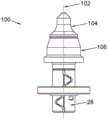
Turning now to fig. 5-10, a pick tool according to the present invention is generally indicated at 100. The excavation tool 100 includes a central axis 102, a strike tip 104, and a support body 106. The excavation tool 100 is symmetrical about a central axis 102 thereof. As best seen in fig. 6, the strike tip 104 is bonded to the support 106 at a non-planar interface 108. Notably, the interface 108 includes two interface surfaces 110, 112 that are coaxial and annular.
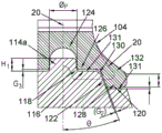
The support body 106 includes a central protrusion or pin 114, the central protrusion or pin 114 being surrounded by a first annular bonding surface 116 and extending radially outward into the first annular bonding surface 116 (see fig. 7). In this embodiment, the central protrusion 114 is a boss (boss) and includes a cylindrical body portion 114a. However, other shapes and contours of the central protrusion 114 are contemplated, such as a conical protrusion, or a frustoconical protrusion, or a hemispherical protrusion. Diameter of cylindrical body portion 114a Preferably about 5mm but may be in the range 3mm to 10 mm. The height H1 of the
 cylindrical portion 114a is preferably about 2.5mm, but may be in the range of 1mm to 5mm. The central protrusion 114 may be undercut by an arcuate recess 118. The recess provides an additional volume into which brazing material can flow and which helpsHelps to enlarge the brazing area.
The first annular bonding surface 116 is connected to the radially outer second annular bonding surface 120 by a shoulder 122. In fig. 7, the shoulder 122 is first arcuate and then linear. The shoulder 122 is positioned intermediate the first annular bonding surface 116 and the second annular bonding surface 120. While as shown in fig. 7, the first and second annular bonding surfaces 116, 120 are disposed perpendicular to the central axis 102, the shoulder 122 is disposed at an acute angle Θ to the central axis 102. The angle Θ is between 10 and 30 degrees, and preferably about 20 degrees.
The first and second annular bonding surfaces 116, 120 are axially spaced apart, i.e., stepped, such that the first annular bonding surface 116 is axially intermediate the central protrusion 114 and the second annular bonding surface 120. The second annular bonding surface 120 may alternatively be located axially intermediate the central protrusion 114 and the first annular bonding surface 116, which, while possible, is not a preferred arrangement as more (rather than less) carbide material may be required in the strike tip 104.
As shown in fig. 8, the strike tip 104 includes a central recess 124 at one end, the central recess 124 for receiving the central protrusion 114 of the support body 106. The internal configuration of the recess 124 is hemispherical, but other shapes are possible. During the early production stage, the function of the central protrusion 114 and the recess 124 is to ensure a good relative position of the strike tip 104 and the support body 106 in the preliminary assembly. They also assist in increasing the density of the green body during pressing during the pre-sintering stage. However, they are not essential to the present invention because they do not directly contribute to the increase in the welding strength, and therefore, they may be omitted. Whether or not the protrusion 114 and recess 124 are included in the strike tip, it is important that the first and second annular interface surfaces 110, 112 are spaced apart to some extent in the axial direction.
The strike tip 104 further includes a third annular bonding surface 126 surrounding the central recess 124 and extending radially outward from the central recess 124. The strike tip 104 also includes a radially outer fourth annular bonding surface 128 connected to the third annular bonding surface 126.
As best seen in fig. 8 and 9, a plurality of dimples 129 project from the fourth annular bonding surface 128. The dimples 129 are arranged equiangularly (equi-angularly) about the central longitudinal axis 102. In this embodiment, since there are 6 pits, the angle Φ at which adjacent pits are spaced is 60 degrees. Any number of dimples may be disposed on the fourth annular bonding surface 128. The dimples help to create a small gap G of approximately 0.3mm between the strike tip 104 and the support body 106 1 . The dimples further increase the surface area of the strike tip 104 to which the braze bonds, which in turn further enhances the shear strength of the bond.
Similar to the support body 106, a second mentioned shoulder 130 connects the third annular joining surface 126 and the fourth annular joining surface 128 of the strike tip 104.
In this embodiment, the first and second shoulders 122, 130 are planar. However, they need not necessarily be planar. It is important that the structural link between the first and second annular interface surfaces 110, 112 extends the length of the interface between the strike tip 104 and the support body 106, but it is not necessarily important how this is achieved. For example, the structural link may simply be a chamfer or, alternatively, a fillet on one of the annular interface surfaces 110, 112.
The third annular bonding surface 126 of the strike tip 104 and the first annular bonding surface 116 of the support body 106 face each other, but they do not abut each other except for optional dimples 129. In addition, the fourth annular bonding surface 128 of the strike tip 104 and the second annular bonding surface 120 of the support body 106 face each other, but they do not abut each other except for some dimples 129. The strike tip 104 and the support 106 are separated by a gap G of about 0.2mm measured at the first and second shoulders 122, 130 2 And (4) separating. Gap G 2 Space is provided for brazing material (not shown) to be located between the strike tip 104 and the support body 106. Similarly, gap G 3 Also provides space for additional braze material (not shown) to make copperThe solder material is located between the strike tip 104 and the support body 106. For assembly, the braze is provided as a ring or annulus, requiring a gap G for the invention 1 And gap G 3 Two rings of (a). However, the braze melts and flows once heated. Braze from G 1 The brazed outer ring of which is along the gap G 2 Towards G 3 To further increase the length of the braze joint. This significantly increases the strength of the bond. Possibly, more than two annular interface surfaces may be provided.
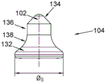
The strike tip 104 includes a protective skirt 132. In this embodiment, a skirt 132 surrounds the central recess 124, the third annular bonding surface 126, and the second shoulder 130. When bonded to the support body 106, the skirt 132 also surrounds the protrusion 114, the first annular bonding surface 116, and the first shoulder 122. The skirt 132 terminates circumferentially at the intersection of the second annular bonding surface 120 and the fourth annular bonding surface 128, generally aligned with the support body 106. Diameter of skirt 132 (see FIG. 10) is at least 25mm. Preferably, diameter
 Between 25mm and 40mm, both extremes included. This overall arrangement is important because it means that the same volume of carbide material in the
 strike tip 104 provides greater protection for the steel support body 106. A volume of carbide material is simply redistributed to where it is most needed, at no additional cost. Notably, when the diameter is At the upper end of the range, the
 strike tip 104 projects radially outward on the support body 106, providing more side protection from wear to the excavation tool 100.
In this embodiment, the two coaxial and annular interface surfaces 110, 112 have different widths measured radially. However, it is contemplated that the interface surfaces 110, 112 may alternatively have the same width. Preferably, the width of the radially outer annular interface surface 112 is smaller than the width of the radially inner annular interface surface 110, which promotes radially inward flow of the braze material, thereby promoting improved joint strength. The radially annular inner interface surface 110 has an outer diameter of about 15mm and a width of about 5mm. The radially annular outer interface surface 112 has an outer diameter of about 25mm and a width of about 3mm.
For clarity, the radially inner annular interface surface 110 includes a first annular bonding surface 116 and a third annular bonding surface 126. The radially outer annular interface surface 112 includes a second annular bonding surface 120 and a fourth annular bonding surface 128.
At the end opposite the central recess 124, the strike tip 104 has a working surface 134, the working surface 134 having a rounded geometry, which may be conical, hemispherical, dome-shaped, truncated, or a combination thereof. Other forms of tips are contemplated within the scope of the present invention, such as hexagonal, quadrilateral and octagonal tips in lateral cross-section.
As best seen in fig. 10, the entire strike tip 104 is generally bell-shaped. The working surface 134 extends into a cylindrical first body surface 136 of the strike tip 104 and is co-linear with the first body surface 136. The first body surface 136 in turn extends into a curved second body surface 138 of the strike tip 104 and is collinear with the second body surface 138. Both the first body surface 136 and the second body surface 138 are continuous and uninterrupted, without any external grooves recessed therein. Similarly, the support body 106 also does not have any kind of external grooves.
In this embodiment, the strike tip 104 is composed of a cemented metal carbide material. In some embodiments, support 106 comprises a cemented metal carbide material having a fracture toughness of at most about 17mpa.m 1/2 Up to about 13MPa.m 1/2 At most about 11MPa.m 1/2 Or even up to about 10MPa.m 1/2 . In some embodiments, the support body 106 comprises a cemented metal carbide material having a fracture toughness of at least about 8mpa.m 1/2 Or toAbout 9MPa.m less 1/2 . In some embodiments, support 106 comprises a cemented metal carbide material having a lateral crack resistance of at least about 2,100mpa, at least about 2,300mpa, at least about 2,700mpa, or even at least about 3,000mpa.
In some embodiments, support body 106 comprises a cemented carbide material comprising metal carbide particles having an average size of at most 8 microns or at most 3 microns. In one embodiment, support body 106 comprises a cemented carbide material comprising metal carbide particles having an average size of at least 0.1 microns.
In some embodiments, support body 106 comprises a cemented metal carbide material comprising at most 13 weight percent, at most about 10 weight percent, at most 7 weight percent, at most about 6 weight percent, or even at most 3 weight percent of a metal binder material, such as cobalt (Co). In some embodiments, support body 106 comprises a cemented metal carbide material comprising at least 1 weight percent, at least 3 weight percent, or at least 6 weight percent metal binder.
The two annular interface surfaces 110, 112 provide improved weld strength and the protective skirt 132 provides improved protection for the support tool 106, which in combination provide the pick tool 100 with extremely superior performance in use. Notably, the useful working life of the impact tool 100 (which may be measured in terms of time, length of cut or gouge, number of operations, etc.) is extended. This superior performance can be achieved with little additional cost and redistribution of carbide material when the arrangement of central protrusion 114 and recess 134 is also included.
Claims (9)
1. A pick tool comprising a central axis, a strike tip and a support, the strike tip being joined to the support at a non-planar interface, the strike tip having a distal free end distal from the non-planar interface, the non-planar interface comprising two interface surfaces that are coaxial and annular, the two interface surfaces extending radially outward perpendicular to the central axis, the two interface surfaces being non-concentric and axially spaced apart, characterized in that a width of an outer interface surface is less than a width of an inner interface surface, the width extending in a radial direction, and wherein the inner interface surface is axially intermediate the outer interface surface and the distal free end, the support comprising a central projection, the strike tip comprising a correspondingly shaped central recess for receiving the central projection, the support comprising a first annular joining surface surrounding and extending from the central projection, the first annular joining surface being connected to a radially outer second annular joining surface, the strike tip comprising a third annular joining surface, the third annular joining surface surrounding the central projection, and the support and a fourth annular joining surface connected to each other at the third annular joining surface, and wherein the support and the third annular joining surface are connected to each other at the third annular joining surface facing each other, the shoulder is disposed at an angle to the central axis, wherein the angle is between 10 and 30 degrees.
2. A pick tool as claimed in claim 1, in which the central projection is undercut by a recess.
3. A pick tool as claimed in claim 1 or claim 2, in which the central projection comprises a cylindrical body portion.
4. A pick tool as claimed in claim 1, in which the angle is about 20 degrees.
5. A pick tool as claimed in claim 1 or claim 4, in which the strike tip is separated from the support body by a gap of at least 0.2mm measured along the shoulder.
6. A pick tool as claimed in claim 1, in which the strike tip comprises a protective skirt.
7. A pick tool as claimed in claim 6, in which the skirt is between 25mm and 40mm in diameter.
8. A pick tool as claimed in claim 1, in which the strike tip comprises a dimple.
9. A pick tool as claimed in claim 1, in which the pick tool is a road milling tool.
Applications Claiming Priority (5)
| Application Number | Priority Date | Filing Date | Title |
|---|---|---|---|
| GBGB1819280.7A GB201819280D0 (en) | 2018-11-27 | 2018-11-27 | Pick tool for road milling |
| GB1819280.7 | 2018-11-27 | ||
| GBGB1901281.4A GB201901281D0 (en) | 2019-01-30 | 2019-01-30 | Pick tool for road milling |
| GB1901281.4 | 2019-01-30 | ||
| PCT/EP2019/082369 WO2020109207A1 (en) | 2018-11-27 | 2019-11-25 | Pick tool for road milling |
Publications (2)
| Publication Number | Publication Date |
|---|---|
| CN113260768A CN113260768A (en) | 2021-08-13 |
| CN113260768B true CN113260768B (en) | 2023-03-10 |
Family
ID=68655549
Family Applications (1)
| Application Number | Title | Priority Date | Filing Date |
|---|---|---|---|
| CN201980077635.2A Active CN113260768B (en) | 2018-11-27 | 2019-11-25 | Digging tool for road milling |
Country Status (9)
| Country | Link |
|---|---|
| US (1) | US11230925B2 (en) |
| EP (1) | EP3864256B1 (en) |
| KR (1) | KR102381855B1 (en) |
| CN (1) | CN113260768B (en) |
| CA (1) | CA3119885C (en) |
| ES (1) | ES2942610T3 (en) |
| FI (1) | FI3864256T3 (en) |
| GB (1) | GB2579448A (en) |
| WO (1) | WO2020109207A1 (en) |
Families Citing this family (2)
| Publication number | Priority date | Publication date | Assignee | Title |
|---|---|---|---|---|
| GB201901712D0 (en) * | 2019-02-07 | 2019-03-27 | Element Six Gmbh | Pick tool for road milling |
| CN115182223A (en) * | 2022-08-16 | 2022-10-14 | 江苏徐工工程机械研究院有限公司 | Road surface milling cutter and road surface milling machine |
Citations (5)
| Publication number | Priority date | Publication date | Assignee | Title |
|---|---|---|---|---|
| US4941711A (en) * | 1988-07-20 | 1990-07-17 | Kennametal Inc. | Cemented carbide tip |
| CN103180549A (en) * | 2010-10-20 | 2013-06-26 | 山特维克知识产权股份有限公司 | Reduced volume cutting tip and cutting bit incorporating same |
| CN104453896A (en) * | 2013-09-19 | 2015-03-25 | 山特维克知识产权股份有限公司 | Cutting bit and bit assembly |
| CN105240010A (en) * | 2014-07-03 | 2016-01-13 | 山特维克知识产权股份有限公司 | Variable angle cutting bit retaining assembly |
| CN105531426A (en) * | 2013-08-01 | 2016-04-27 | 卡特彼勒公司 | Ground engaging tool assembly |
Family Cites Families (6)
| Publication number | Priority date | Publication date | Assignee | Title |
|---|---|---|---|---|
| US7635168B2 (en) * | 2006-08-11 | 2009-12-22 | Hall David R | Degradation assembly shield |
| US7661765B2 (en) * | 2006-08-11 | 2010-02-16 | Hall David R | Braze thickness control |
| US8038223B2 (en) * | 2007-09-07 | 2011-10-18 | Schlumberger Technology Corporation | Pick with carbide cap |
| US8210618B2 (en) | 2007-08-23 | 2012-07-03 | Sandvik Intellectual Property Ab | Reduced volume cutting tip and cutter bit assembly incorporating same |
| US8636325B2 (en) | 2008-11-05 | 2014-01-28 | Gregory Greenspan | Mining and demolition tool |
| CN106351657A (en) * | 2016-10-09 | 2017-01-25 | 杨岗 | Novel cutting pick |
-
2019
- 2019-11-25 US US17/309,264 patent/US11230925B2/en active Active
- 2019-11-25 KR KR1020217015524A patent/KR102381855B1/en active IP Right Grant
- 2019-11-25 ES ES19809063T patent/ES2942610T3/en active Active
- 2019-11-25 CN CN201980077635.2A patent/CN113260768B/en active Active
- 2019-11-25 GB GB1917103.2A patent/GB2579448A/en not_active Withdrawn
- 2019-11-25 WO PCT/EP2019/082369 patent/WO2020109207A1/en unknown
- 2019-11-25 CA CA3119885A patent/CA3119885C/en active Active
- 2019-11-25 FI FIEP19809063.1T patent/FI3864256T3/en active
- 2019-11-25 EP EP19809063.1A patent/EP3864256B1/en active Active
Patent Citations (5)
| Publication number | Priority date | Publication date | Assignee | Title |
|---|---|---|---|---|
| US4941711A (en) * | 1988-07-20 | 1990-07-17 | Kennametal Inc. | Cemented carbide tip |
| CN103180549A (en) * | 2010-10-20 | 2013-06-26 | 山特维克知识产权股份有限公司 | Reduced volume cutting tip and cutting bit incorporating same |
| CN105531426A (en) * | 2013-08-01 | 2016-04-27 | 卡特彼勒公司 | Ground engaging tool assembly |
| CN104453896A (en) * | 2013-09-19 | 2015-03-25 | 山特维克知识产权股份有限公司 | Cutting bit and bit assembly |
| CN105240010A (en) * | 2014-07-03 | 2016-01-13 | 山特维克知识产权股份有限公司 | Variable angle cutting bit retaining assembly |
Also Published As
| Publication number | Publication date |
|---|---|
| CA3119885C (en) | 2023-04-04 |
| FI3864256T3 (en) | 2023-06-07 |
| US11230925B2 (en) | 2022-01-25 |
| KR102381855B1 (en) | 2022-04-04 |
| GB201917103D0 (en) | 2020-01-08 |
| EP3864256A1 (en) | 2021-08-18 |
| GB2579448A (en) | 2020-06-24 |
| CN113260768A (en) | 2021-08-13 |
| US20210355825A1 (en) | 2021-11-18 |
| EP3864256B1 (en) | 2023-03-15 |
| KR20210073583A (en) | 2021-06-18 |
| ES2942610T3 (en) | 2023-06-05 |
| WO2020109207A1 (en) | 2020-06-04 |
| CA3119885A1 (en) | 2020-06-04 |
Similar Documents
| Publication | Publication Date | Title |
|---|---|---|
| US9605538B2 (en) | Cutting pick tool | |
| US7464993B2 (en) | Attack tool | |
| AU640376B2 (en) | Rotatable cutting tool | |
| US7445294B2 (en) | Attack tool | |
| US7384105B2 (en) | Attack tool | |
| CN113260768B (en) | Digging tool for road milling | |
| US20100237135A1 (en) | Methods For Making An Attack Tool | |
| EP3524774A1 (en) | New cutting pick | |
| US8777326B2 (en) | Pick with hardened core assembly | |
| CN113785103B (en) | Digging tool for road milling | |
| JP2008144541A (en) | Drilling bit | |
| CN211173946U (en) | PDC drill tooth for oil and gas well drilling and drill bit using same | |
| US11952896B2 (en) | Rotary tool with thermally stable diamond | |
| CN212177130U (en) | Diamond cutting tooth, roadway heading machine, coal mining machine and shield machine | |
| US20200300086A1 (en) | Bit | |
| AU2018100703A4 (en) | New cutting pick |
Legal Events
| Date | Code | Title | Description |
|---|---|---|---|
| PB01 | Publication | ||
| PB01 | Publication | ||
| SE01 | Entry into force of request for substantive examination | ||
| SE01 | Entry into force of request for substantive examination | ||
| GR01 | Patent grant | ||
| GR01 | Patent grant |