Production line and production process for wind power slip ring
Technical Field
The invention relates to the field of production of wind power slip rings, in particular to a production line and a production process for a wind power slip ring.
Background
Wind-powered electricity generation sliding ring includes stator part and rotor part, and its inside is provided with stator side binding post, rotor side binding post, and binding post all welds through the PCB board. An assembly shaft assembly is further arranged in the stator shell and comprises a power slide way and a signal slide way.
Among the prior art, the production of wind-powered electricity generation sliding ring includes welding and assembly, and the welding includes: the method comprises the steps of signal ring welding, power ring welding and PCB board welding, wherein the assembly comprises assembly of an assembly shaft component, assembly of a stator part and assembly of a rotor part. When welding the PCB board, traditional welding process still welds through the manual work, and its efficiency is not high, needs the manual work to shift around the welding. When the power slide way is welded, the power ring and the power shaft need to be preassembled firstly, then the contact surfaces of the two sides of the power ring and the power shaft are welded through the welding gun head, a certain included angle exists between the welding gun head and a vertical line, and the welding precision is not high.
Disclosure of Invention
In order to solve the defects in the background art, the invention aims to provide a production line and a production process for a wind power slip ring.
The purpose of the invention can be realized by the following technical scheme:
a production line for a wind power slip ring comprises a stator part and a rotor part arranged at the side end of the stator part, wherein the stator part comprises a stator shell and a junction box arranged at the upper end of the stator shell, a stator side wiring terminal is arranged in the junction box, the side wiring terminal is fixedly arranged through a first PCB, and an assembly shaft assembly is arranged in the stator shell;
the rotor part comprises a rotor shell and a rotor side wiring terminal arranged in the rotor shell, and the rotor side wiring terminal is fixedly installed through a second PCB;
the production line comprises pre-assembly equipment and final assembly equipment of the wind power slip ring, wherein the pre-assembly equipment comprises a welding device, and the final assembly equipment comprises an assembling device.
Furthermore, the assembly shaft assembly comprises a power slide way and a signal slide way, the power slide way comprises a power shaft, the outer wall of the power shaft is provided with a grounding ring and a plurality of power rings, and a first sealing ring is sleeved between the power rings;
the signal slide includes signal axle and sets up a plurality of signal mount pad on the signal axle, and the tip of signal axle and the tip fixed mounting of power shaft install a plurality of signal rings on the signal mount pad, all overlap between the signal ring and be equipped with the second sealing ring.
Furthermore, the welding device comprises a workbench, wherein conveying mechanisms are respectively arranged on two sides of the workbench and respectively used for feeding and discharging;
the upper end of the workbench is provided with two mechanical arms, and the front ends of the mechanical arms are respectively provided with a transfer component for transferring the material on the conveying mechanism at one end onto the workbench and transferring the material on the workbench onto the conveying mechanism at the other end;
horizontal drive mechanism is installed to the top of workstation intermediate position, and welding mechanism is installed to horizontal drive mechanism's bottom, and welding mechanism's below is provided with first clamping component and second clamping component, and clamping component all is used for carrying out the centre gripping to power shaft and PCB board.
Furthermore, two through holes which are symmetrically arranged are formed in one side of the upper end of the workbench, and a through cross-shaped sliding groove is formed in the end portion of the workbench.
Furthermore, the mechanical arm comprises a rotating shaft which is rotatably connected with the through hole, a straight gear pair is arranged at the bottom end of the rotating shaft, the bottom end of the straight gear pair is driven by a servo motor, an installation base is fixed at the upper end of the rotating shaft, a first manipulator is rotatably connected to the upper end of the installation base, a second manipulator is rotatably connected to the side end of the first manipulator, a third manipulator is rotatably connected to the side end of the second manipulator, a fourth manipulator is rotatably connected to the side end of the third manipulator, and a fifth manipulator is rotatably connected to the side end of the fourth manipulator;
the manipulator is characterized in that a first push rod is rotatably connected between the mounting base and the first manipulator, a second push rod is rotatably connected between the first manipulator and the second manipulator, a third push rod is rotatably connected between the second manipulator and the third manipulator, a fourth push rod is rotatably connected between the third manipulator and the fourth manipulator, and a fifth push rod is rotatably connected between the fourth manipulator and the fifth manipulator.
Furthermore, the transfer component comprises a connecting base fixed at the bottom end of the fifth manipulator, two connecting bottom plates which are arranged in parallel are fixed at the bottom end of the connecting base close to the side end through a first buffer spring, two first connecting rods which are arranged in parallel are arranged between the connecting bottom plates, a second connecting rod is fixed between the first connecting rods, a first pneumatic cylinder fixed at the bottom end of the connecting base is arranged at the upper end of the second connecting rod, and the second connecting rod is connected with the output end of the first pneumatic cylinder;
the two ends of the first connecting rod are respectively sleeved with a sliding sleeve in a sliding mode, a first rotating pair is arranged at the upper end of the sliding sleeve, supporting rods are rotatably connected between the first rotating pair and a second rotating pair arranged at the bottom end of the connecting base, second buffer springs are fixed at the outer side ends of the sliding sleeves, the second buffer springs are sleeved on the first connecting rod, and the end portions of the second buffer springs are fixed on the connecting bottom plate;
the bottom of sliding sleeve is fixed with the lateral shifting board, and the both sides end of lateral shifting board all is provided with the centre gripping curb plate, and the spacing of lateral shifting board upper end setting is spacing to cooperate with the spacing groove that the connecting bottom plate bottom was seted up.
Furthermore, the horizontal driving mechanism comprises a first linear electric cylinder and a second linear electric cylinder which are fixed right above the workbench through a stand column, the first linear electric cylinder and the second linear electric cylinder are symmetrically arranged in two numbers, and the first linear electric cylinder and the second linear electric cylinder form a rectangular frame body;
the first linear cylinder comprises a first cylinder guide rail and a first cylinder sliding block which is arranged on the first cylinder guide rail in a sliding mode, first connecting blocks are arranged at the side ends of the first cylinder sliding block, and first connecting columns are arranged among the first connecting blocks;
the second straight line electric cylinder comprises a second electric cylinder guide rail and a second electric cylinder sliding block which is arranged on the second electric cylinder guide rail in a sliding mode, a second connecting block is arranged at the side end of the second electric cylinder sliding block, a second connecting column is arranged between the second connecting blocks, fixing seats are arranged on the second connecting column and the first connecting column, and the fixing seats are arranged on the second connecting column and the first connecting column in a sliding mode.
Further, welding mechanism is including fixing the second pneumatic cylinder in the fixing base bottom, and the cylinder body side of second pneumatic cylinder is fixed with the joint piece, and the below of joint piece is connected with the connecting plate through the telescopic link, and first motor is installed to the side of connecting plate, and the output of first motor is fixed with the rotor plate, is provided with the third revolute pair between the second pneumatic rod of rotor plate and second pneumatic cylinder below, and the outer tip of rotor plate is provided with the mounting panel, is provided with the welding rifle head on the mounting panel.
Further, the first clamping part symmetry is provided with two, and first clamping part is including fixing the third pneumatic cylinder in the workstation upper end, and the end fixing of the third pneumatic rod on the third pneumatic cylinder has the sliding plate, and the bottom of sliding plate is provided with the cross slider with cross spout sliding fit, and one side end of sliding plate is fixed with the second motor, and the opposite side end of sliding plate is fixed with the sleeve pipe, and the sheathed tube lateral wall is opened has the groove of dodging, and the output of second motor is fixed with vacuum suction nozzle, and vacuum suction nozzle sets up at the intraductal, vacuum suction nozzle and vacuum pump connection.
Furthermore, the second clamping component comprises an installation bearing seat fixed in the middle of the workbench, a first rectangular groove and a second rectangular groove which penetrate through the two sides are formed in the side end of the installation bearing seat, an internal cavity is formed between the first rectangular groove and the second rectangular groove, and a plurality of T-shaped sliding grooves which are arranged in parallel are formed in the upper end of the installation bearing seat;
a third motor is arranged at the side end of the mounting and bearing seat, the output end of the third motor is connected with a rotating gear, the rotating gear is rotatably arranged in the inner cavity, a first linkage plate in sliding fit with the first rectangular groove is arranged below the rotating gear, a first rack meshed with the rotating gear is arranged at the upper end of the first linkage plate, a first clamping plate is arranged at the outer end of the first linkage plate, a plurality of first through holes are formed in the side wall of the first clamping plate, a second linkage plate in sliding fit with the second rectangular groove is arranged above the rotating gear, a second rack meshed with the rotating gear is arranged at the bottom end of the second linkage plate, a second clamping plate is arranged at the outer end of the second linkage plate, and a plurality of second through holes are formed in the side wall of the second clamping plate;
the inner sides of the first clamping plate and the second clamping plate are respectively provided with a third clamping plate, the outer end part of the third clamping plate is provided with a third clamping rod in sliding fit with the first through hole and the second through hole, the third clamping rod is sleeved with a fourth buffer spring, the fourth buffer springs are respectively fixed between the second clamping plate and the third clamping plate and between the first clamping plate and the third clamping plate, the inner side end of the third clamping plate is provided with a limiting hole, and the bottom end of the third clamping plate is provided with a T-shaped sliding block in sliding fit with a T-shaped sliding groove;
the clamping device is characterized in that two fourth clamping plates which are symmetrically arranged are arranged between the third clamping plates, the outer end portions of the fourth clamping plates are provided with fourth clamping rods which are concentrically arranged with limiting holes, limiting pieces arranged on the fourth clamping rods are attached to the third clamping plates, the inner side walls of the fourth clamping plates are provided with arc-shaped notches, the side walls of the arc-shaped notches are provided with a plurality of clamping grooves, and the arc-shaped notches are matched with power shafts and are matched with the power rings.
The invention has the beneficial effects that:
1. the automatic welding machine is provided with the mechanical arm and the transfer component, in the using process, the first pneumatic cylinder is driven, the support rod drives the sliding sleeve to transversely slide on the first connecting rod, so that the clamping side plates on two sides are driven to be close to or far away from each other, a PCB or a power shaft arranged on the conveying mechanism on one side can be clamped, the PCB or the power shaft can be conveniently transferred to the upper part of the workbench, and the PCB or the power shaft can be conveniently transferred to the conveying mechanism on the other side after welding is finished, so that the automation efficiency is improved;
2. the PCB welding machine is provided with the first clamping component and the second clamping component, and can drive the third motor when welding a PCB or welding a power shaft aiming at the welding operation of the PCB or the power shaft, the rotating gear rotates clockwise, and the third clamping plate is utilized to clamp the PCB;
when the power shaft is welded, the power shaft and the power ring are clamped by the fourth clamping plate (the clamping force at the moment is adjusted to be zero), so that the vacuum suction nozzle and the end part of the power shaft are adsorbed, the power shaft and the power ring can rotate in the arc-shaped notch by driving the second motor, meanwhile, the included angle between the welding gun head and the vertical line is adjusted by driving the first motor, the end A and the end B of the contact surface of the power shaft and the power ring are respectively welded, the welding gun is suitable for various conditions, and the automatic operation welding efficiency is higher;
3. the welding gun head comprises a welding gun head body, a welding gun head is arranged on the welding gun head body, a first motor is arranged on the welding gun head body, a second pneumatic cylinder is arranged on the welding gun head body, and a horizontal driving mechanism and a welding mechanism are arranged on the welding gun head body.
Drawings
In order to more clearly illustrate the embodiments or technical solutions in the prior art of the present invention, the drawings used in the description of the embodiments or prior art will be briefly described below, and it is obvious for those skilled in the art to obtain other drawings without creative efforts;
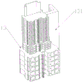
FIG. 1 is a schematic structural diagram of a wind power slip ring of the invention;
FIG. 2 is a schematic cross-sectional view of a wind power slip ring of the present invention;
FIG. 3 is a schematic view of a stator side terminal of the present invention;
FIG. 4 is a schematic view of a rotor side terminal of the present invention;
FIG. 5 is a schematic view of the assembled shaft assembly of the present invention;
FIG. 6 is an exploded view of the assembly shaft assembly of the present invention;
FIG. 7 is an overall schematic view of the welding apparatus of the present invention;
FIG. 8 is a schematic view of the inventive work bench;
FIG. 9 is a schematic view of a robot arm according to the present invention;
FIG. 10 is a schematic view of a robot arm according to the present invention;
FIG. 11 is a schematic view of a first perspective of the transfer member of the present invention;
FIG. 12 is a schematic view of a second perspective of the transfer member of the present invention;
FIG. 13 is a schematic view of the horizontal drive mechanism of the present invention;
FIG. 14 is a schematic view of a welding mechanism of the present invention;
FIG. 15 is a schematic view of a first clamping member of the present invention;
FIG. 16 is a cross-sectional schematic view of a first clamping member of the present invention;
FIG. 17 is a schematic view of a second clamping member of the present invention;
FIG. 18 is a schematic view of a second clamping member of the present invention;
FIG. 19 is a schematic view of the mounting socket of the present invention;
FIG. 20 is a first perspective cross-sectional view of the second clamping member of the present invention;
FIG. 21 is a second perspective cross-sectional view of the second clamping member of the present invention;
FIG. 22 is a schematic view of the A and B ends of the contact surfaces of the power shaft and power ring of the present invention.
Detailed Description
The technical solutions in the embodiments of the present invention will be clearly and completely described below with reference to the drawings in the embodiments of the present invention, and it is obvious that the described embodiments are only a part of the embodiments of the present invention, and not all of the embodiments. All other embodiments, which can be derived by a person skilled in the art from the embodiments given herein without making any creative effort, shall fall within the protection scope of the present invention.
A production line for wind power slip rings is disclosed, as shown in FIGS. 1-4, the wind power slip ring comprises a stator part 1 and a rotor part 2 installed at the side end of the stator part 1, the stator part 1 comprises a stator housing 11 and a junction box 12 arranged at the upper end of the stator housing 11, a stator side connection terminal 13 is arranged in the junction box 12, the side connection terminal 13 is fixedly installed through a first PCB 131, and an assembly shaft assembly 3 is arranged in the stator housing 11. The rotor portion 2 includes a rotor case 21 and a rotor-side terminal 22 provided in the rotor case 21, and the rotor-side terminal 22 is fixedly mounted through a second PCB board 221.
As shown in fig. 5 and 6, the assembly shaft assembly 3 comprises a power slideway 31 and a signal slideway 32, the power slideway 31 comprises a power shaft 311, a grounding ring 312 and a plurality of power rings 313 are mounted on the outer wall of the power shaft 311, and first sealing rings 313 are respectively sleeved between the power rings 313; the signal slide way 32 comprises a signal shaft 321 and a plurality of signal mounting seats 322 arranged on the signal shaft 321, the end portions of the signal shaft 321 and the power shaft 311 are fixedly mounted, a plurality of signal rings 323 are mounted on the signal mounting seats 322, and second sealing rings 324 are sleeved among the signal rings 323.
As shown in fig. 7, the production line of the wind power slip ring comprises a pre-assembly device and a final assembly device of the wind power slip ring, wherein the pre-assembly device comprises a welding device, and the final assembly device comprises an assembling device. The welding device comprises a workbench 30, wherein conveying mechanisms 10 are respectively arranged on two sides of the workbench 30, the conveying mechanisms 10 are respectively used for feeding conveying and discharging conveying, two mechanical arms 4 are arranged at the upper end of the workbench 30, and transfer parts 5 are respectively arranged at the front ends of the mechanical arms 4 and are used for transferring materials on the conveying mechanism 10 at one end to the workbench 30 and transferring materials on the workbench 30 to the conveying mechanism 10 at the other end;
the horizontal driving mechanism 6 is installed above the middle position of the workbench 30, the welding mechanism 7 is installed at the bottom end of the horizontal driving mechanism 6, the first clamping component 8 and the second clamping component 9 are arranged below the welding mechanism 7, and the clamping components are all used for clamping the power shaft 311 and the PCB.
As shown in fig. 8, two through holes 301 are symmetrically formed in the upper end side of the table 30, and a cross slide groove 302 is formed in the end of the table 30.
As shown in fig. 9 and 10, the robot arm 4 includes a rotation shaft 421 rotatably connected to the through hole 301, a spur gear pair 42 is provided at a bottom end of the rotation shaft 421, a bottom end of the spur gear pair 42 is driven by a servo motor, a mounting base 43 is fixed to an upper end of the rotation shaft 421, a first robot arm 44 is rotatably connected to an upper end of the mounting base 43, a second robot arm 45 is rotatably connected to a side end of the first robot arm 44, a third robot arm 46 is rotatably connected to a side end of the second robot arm 45, a fourth robot arm 47 is rotatably connected to a side end of the third robot arm 46, and a fifth robot arm 48 is rotatably connected to a side end of the fourth robot arm 47;
a first push rod 431 is rotatably connected between the mounting base 43 and the first manipulator 44, a second push rod 441 is rotatably connected between the first manipulator 44 and the second manipulator 45, a third push rod 451 is rotatably connected between the second manipulator 45 and the third manipulator 46, a fourth push rod 461 is rotatably connected between the third manipulator 46 and the fourth manipulator 47, and a fifth push rod 471 is rotatably connected between the fourth manipulator 47 and the fifth manipulator 48.
The entire robot arm 4 can be rotated to adjust the position by driving the servo motor at the bottom end of the spur gear pair 42. By driving the plurality of push rods, the position of the fifth robot arm 48 can be freely adjusted.
As shown in fig. 11 and 12, the transfer unit 5 includes a connecting base 51 fixed at the bottom end of the fifth manipulator 48, two connecting bottom plates 53 arranged in parallel are fixed at the bottom end of the connecting base 51 near the side end through a first buffer spring 52, two first connecting rods 531 arranged in parallel are arranged between the connecting bottom plates 53, a second connecting rod 532 is fixed between the first connecting rods 531, a first pneumatic cylinder 57 fixed at the bottom end of the connecting base 51 is arranged at the upper end of the second connecting rod 532, and the second connecting rod 532 is connected with the output end of the first pneumatic cylinder 57;
a sliding sleeve 54 is respectively slidably sleeved at two ends of the first connecting rod 531, a first revolute pair 541 is arranged at the upper end of the sliding sleeve 54, a supporting rod 55 is rotatably connected between the first revolute pair 541 and a second revolute pair 511 arranged at the bottom end of the connecting base 51, a second buffer spring 542 is fixed at the outer side end of the sliding sleeve 54, the second buffer spring 542 is sleeved on the first connecting rod 531, and the end part of the second buffer spring 542 is fixed on the connecting bottom plate 53;
the bottom end of the sliding sleeve 54 is fixed with a transverse moving plate 56, both side ends of the transverse moving plate 56 are provided with clamping side plates 561, and a limiting strip 562 arranged at the upper end of the transverse moving plate 56 is in limiting fit with a limiting groove 530 arranged at the bottom end of the connecting bottom plate 53.
By driving the first pneumatic cylinder 57, the supporting rod 55 drives the sliding sleeve 54 to slide laterally on the first connecting rod 531, and further drives the clamping side plates 561 at two sides to move close to or away from each other, so as to clamp the PCB or the power shaft 311 disposed on the conveying mechanism 10 and transfer the PCB or the power shaft.
As shown in fig. 13, the horizontal driving mechanism 6 includes a first linear electric cylinder 61 and a second linear electric cylinder 62 fixed directly above the table 30 by a column, two first linear electric cylinders 61 and two second linear electric cylinders 62 are symmetrically arranged, and the first linear electric cylinder 61 and the second linear electric cylinder 62 form a rectangular frame;
the first linear electric cylinder 61 comprises a first electric cylinder guide rail 611 and a first electric cylinder slider 612 arranged on the first electric cylinder guide rail 611 in a sliding mode, the side ends of the first electric cylinder slider 612 are provided with first connecting blocks 63, and first connecting columns 631 are arranged between the first connecting blocks 63;
the second linear electric cylinder 62 comprises a second electric cylinder guide rail 621 and a second electric cylinder sliding block 622 slidably arranged on the second electric cylinder guide rail 621, a second connecting block 64 is arranged at the side end of the second electric cylinder sliding block 622, a second connecting column 641 is arranged between the second connecting blocks 64, a fixing seat 65 is arranged on the second connecting column 641 and the first connecting column 631, and the fixing seat 65 is slidably arranged on the second connecting column 641 and the first connecting column 631.
By driving the first linear electric cylinder 61 and the second linear electric cylinder 62, the holder 65 can be moved horizontally in the area of the first linear electric cylinder 61 and the second linear electric cylinder 62.
As shown in fig. 7, the welding mechanism 7 includes a second pneumatic cylinder 71 fixed at the bottom end of the fixing seat 65, a clamping block 72 is fixed at the cylinder body side end of the second pneumatic cylinder 71, a connecting plate 73 is connected below the clamping block 72 through a telescopic rod 721, a first motor 74 is installed at the side end of the connecting plate 73, a rotating plate 75 is fixed at the output end of the first motor 74, a third revolute pair 751 is arranged between the rotating plate 75 and a second pneumatic rod 712 below the second pneumatic cylinder 71, an installation plate 76 is arranged at the outer end of the rotating plate 75, and a welding gun head 761 is arranged on the installation plate 76.
In use, the height of the welding torch head 761 can be adjusted by driving the second pneumatic cylinder 71. By driving the first motor 74, the angle between the welding torch head 761 and the vertical line can be adjusted.
As shown in fig. 15 and 16, two first clamping members 8 are symmetrically arranged, each first clamping member 8 includes a third pneumatic cylinder 81 fixed at the upper end of the worktable 30, a sliding plate 83 is fixed at the end of a third pneumatic rod 82 on the third pneumatic cylinder 81, a cross slide 831 slidably engaged with the cross slide groove 302 is arranged at the bottom end of the sliding plate 83, a second motor 84 is fixed at one end of the sliding plate 83, a sleeve 85 is fixed at the other end of the sliding plate 83, an avoiding groove 851 is formed on the side wall of the sleeve 85, a vacuum suction nozzle 86 is fixed at the output end of the second motor 84, the vacuum suction nozzle 86 is arranged in the sleeve 85, and the vacuum suction nozzle 86 is connected with a vacuum pump.
As shown in fig. 17-21, the second clamping member 9 includes a mounting socket 91 fixed at the middle position of the worktable 30, a first rectangular groove 911 and a second rectangular groove 912 penetrating through both sides are formed at the side end of the mounting socket 91, an internal cavity 913 is arranged between the first rectangular groove 911 and the second rectangular groove 912, and a plurality of T-shaped sliding grooves 914 arranged in parallel are formed at the upper end of the mounting socket 91;
a third motor 92 is arranged at the side end of the mounting bearing seat 91, the output end of the third motor 92 is connected with a rotating gear 921, the rotating gear 921 is rotatably arranged in the internal cavity 913, a first linkage plate 93 which is in sliding fit with the first rectangular groove 911 is arranged below the rotating gear 921, a first rack 931 which is engaged with the rotating gear 921 is arranged at the upper end of the first linkage plate 93, a first clamping plate 932 is arranged at the outer end of the first linkage plate 93, a plurality of first through holes 9321 are arranged on the side wall of the first clamping plate 932, a second linkage plate 94 which is in sliding fit with the second rectangular groove 912 is arranged above the rotating gear 921, a second rack 941 which is engaged with the rotating gear 921 is arranged at the bottom end of the second linkage plate 94, a second clamping plate 942 is arranged at the outer end of the second linkage plate 94, and a plurality of second through holes 9421 are arranged on the side wall of the second clamping plate 942;
the inner sides of the first clamping plate 932 and the second clamping plate 942 are both provided with a third clamping plate 95, the outer end part of the third clamping plate 95 is provided with a third clamping rod 951 which is in sliding fit with the first through hole 9321 and the second through hole 9421, the third clamping rod 951 is sleeved with a fourth buffer spring 952, the fourth buffer spring 952 is respectively fixed between the second clamping plate 942 and the third clamping plate 95 and between the first clamping plate 932 and the third clamping plate 95, the inner side end of the third clamping plate 95 is provided with a limiting hole 953, and the bottom end of the third clamping plate 95 is provided with a T-shaped sliding block 954 which is in sliding fit with the T-shaped sliding groove 914;
two symmetrical fourth clamping plates 96 are arranged between the third clamping plates 95, fourth clamping rods 961 concentrically arranged with limiting holes 953 are arranged at the outer end parts of the fourth clamping plates 96, limiting pieces 962 arranged on the fourth clamping rods 961 are attached to the third clamping plates 95, arc-shaped notches 963 are formed in the inner side walls of the fourth clamping plates 96, a plurality of clamping grooves 964 are formed in the side walls of the arc-shaped notches 963, the arc-shaped notches 963 are matched with the power shaft 311, and the clamping grooves 964 are matched with the power ring 313. By driving the third motor 92, the rack and pinion are engaged, and the first clamping plate 932 and the second clamping plate 942 move towards each other to clamp the power shaft 311 and the PCB.
When a PCB is welded, the second clamping component 9 transfers the PCB from the conveying mechanism 10 to the mounting bearing seat 91 through the transfer component 5 on one side as shown in FIG. 18, the third motor 92 is driven, the rotating gear 921 rotates clockwise, the PCB is clamped by the third clamping plate 95, the position of a welding gun head 761 is adjusted by driving the horizontal driving mechanism 6 and the second pneumatic cylinder 71, the PCB is welded, after the welding is finished, the clamping of the second clamping component 9 is released, and the PCB is transferred to the conveying mechanism 10 on the other side through the transfer component 5 on the other side;
when the power shaft 311 is welded, the second clamping component 9 transfers the power shaft 311 and the power ring 313 from the conveying mechanism 10 to the mounting bearing seat 91 through the transfer component 5 on one side as shown in fig. 17 to drive the third motor 92, the rotating gear 921 rotates clockwise, the power shaft 311 and the power ring 313 are clamped by the fourth clamping plate 96 (the clamping force at this time is adjusted to be zero), the arc-shaped notch 963 is matched with the power shaft 311, the clamping slot 964 is matched with the power ring 313, and at this time, the power shaft 311 and the power ring 313 can rotate in the arc-shaped notch 963;
driving the third pneumatic cylinder 81 to make the end of the power shaft 311 enter the sleeve 85, so that the vacuum suction nozzle 86 and the end of the power shaft 311 are sucked, and driving the second motor 84, the power shaft 311 and the power ring 313 can rotate in the arc-shaped notch 963;
and driving the horizontal driving mechanism 6 and the second pneumatic cylinder 71 to adjust the position of the welding gun head 761, simultaneously adjusting the included angle between the welding gun head 761 and the vertical line by driving the first motor 74, respectively welding the end A and the end B of the contact surface of the power shaft 311 and the power ring 313, as shown in fig. 22, after the welding is finished, releasing the clamping of the first clamping component 8 and the second clamping component 9, and transferring the PCB to the conveying mechanism 10 on the other side through the transferring component 5 on the other side.
A production process for a wind power slip ring comprises the following steps:
first, preassemble
1. Signal ring and power ring assembly
2. Signal ring, power ring welding
3. PCB welding
Second, final assembly
1. Rotor side wiring terminal assembly
2. Stator side binding post assembly
3. Assembly shaft assembly
4. The stator part and the rotor part are assembled.
The foregoing shows and describes the general principles, essential features, and advantages of the invention. It will be understood by those skilled in the art that the present invention is not limited to the embodiments described above, which are described in the specification and illustrated only to illustrate the principle of the present invention, but that various changes and modifications may be made therein without departing from the spirit and scope of the present invention, which fall within the scope of the invention as claimed.