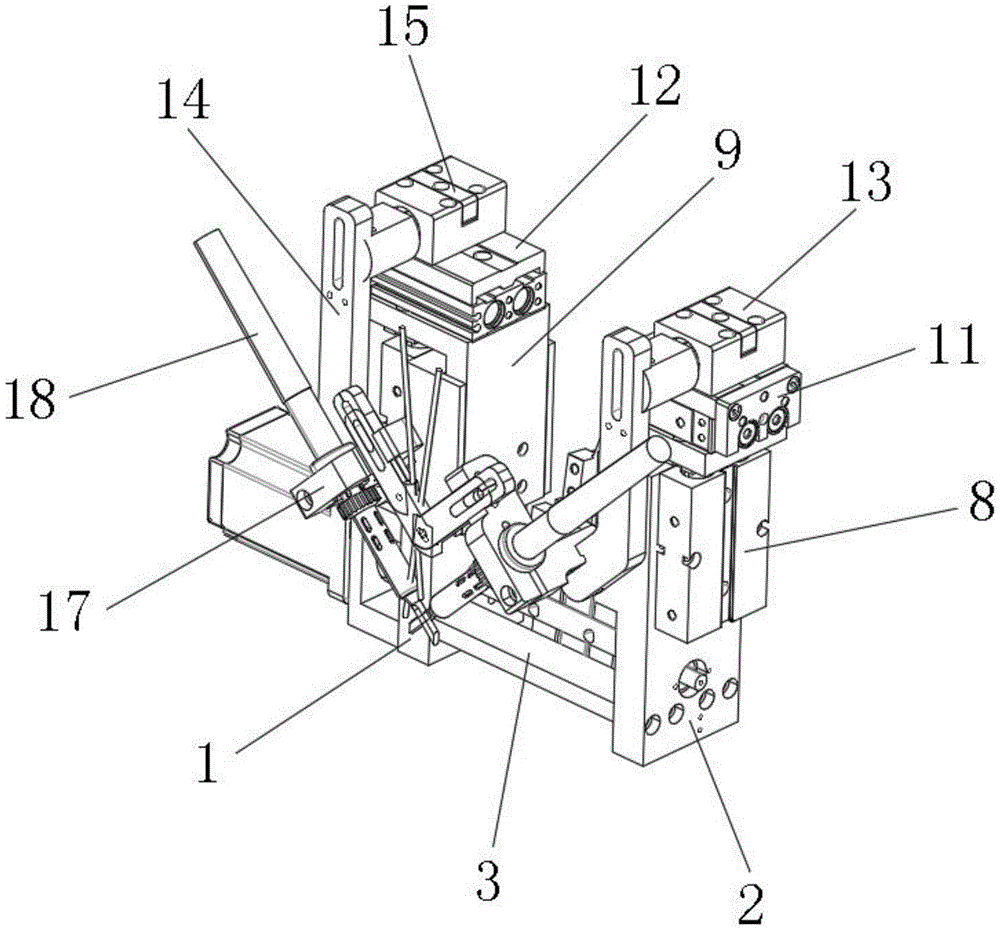
Swing buffer structure of DC soldering machine handle
Technical Field
The utility model relates to a soldering tin machine field especially relates to DC soldering tin machine handle swing buffer structure.
Background
The automatic tin soldering machine is a device capable of replacing manual soldering, and is a high-precision automatic device consisting of a plurality of mechanical arms, a tin feeding system, a control system and a soldering iron system, wherein the mechanical arms are important components in the automatic tin soldering machine, and the mechanical arms are controlled by a microcomputer, so that processes which are difficult to achieve manually, such as spot welding, drag welding, circular welding, straight welding, irregular welding, automatic cleaning and the like, can be achieved.
There is the manipulator of multiple different grade type in the existing market, but there is certain defect in the manipulator structural design of existing equipment, though can realize the regulation of multi-angle or direction, so that weld in welding position, but its welding arm adopts fixed structural design more, in welding process, does not have any buffer structure, welding part and work piece contact tension appear easily or have great clearance, thereby it is all relatively poor to lead to welding precision and the welding quality of welding product, can't reach higher welding standard.
Therefore, it is desirable to provide a swing buffering structure for a DC soldering machine handle to solve the above problems.
SUMMERY OF THE UTILITY MODEL
The utility model aims to solve the technical problem that there is certain defect in the manipulator structural design of existing equipment, though can realize the regulation of multi-angle or direction, so that weld in the welded position, but its welding arm adopts fixed structural design more, in welding process, does not have any buffer structure, weld part and work piece contact tension appear easily or there is great clearance, thereby the welding precision and the welding quality that lead to welding product are all relatively poor, can't reach higher welding standard.
In order to solve the technical problem, the utility model discloses a technical scheme be: providing a handle swinging buffer structure of a DC soldering machine, which comprises a first support frame and a second support frame, wherein a connecting plate is fixedly connected to the bottom between the first support frame and the second support frame, a rotating shaft is rotatably connected between the first support frame and the second support frame, a motor support is fixedly connected to the bottom of the outer wall of the first support frame, a servo motor corresponding to the rotating shaft is installed in the center of the outer side of the motor support, and a rotary clamping cylinder is installed on the outer wall of the rotating shaft;
lifting cylinders are respectively arranged on the outer sides of the first support frame and the second support frame, lifting supports are respectively fixedly connected to the top ends of the two lifting cylinder piston rods, transverse telescopic cylinders are respectively arranged at the tops of the two lifting supports, mounting plates are respectively fixedly connected to the top ends of the two transverse telescopic cylinder piston rods, and supporting seats are respectively fixedly connected to the tops of the inner sides of the two mounting plates;
the tops of the two supporting seats are fixedly connected with mounting seats, and the front ends of the two mounting seats are rotatably connected with mechanical swing arms;
the top centers of the two mounting seats are respectively provided with a buffer mechanism corresponding to the mechanical swing arms, each buffer mechanism comprises a limiting plate, the outer walls of the two mechanical swing arm supporting shafts are respectively fixedly connected with the limiting plate, and one side of the top centers of the two mounting seats is respectively provided with a buffer spring corresponding to the limiting plate;
two equal fixedly connected with mounting bracket in bottom of mechanical swing arm, two the welding rifle is all installed at the center of mounting bracket.
Preferably, the first support frame, the second support frame and the connecting plate are of an integrated structure, and the first support frame, the second support frame and the connecting plate which are designed in an integrated structure are simpler and firmer in structure.
Preferably, the output shaft of the servo motor is fixedly connected with one end of the rotating shaft through the coupler, so that the output shaft of the servo motor can drive the rotating shaft to rotate, and the rotary clamping cylinder is driven to rotate to a specified welding position.
Preferably, the lifting support is of an L-shaped structural design, and can play a role in supporting and limiting sliding due to the L-shaped structural design.
Preferably, the inner sides of the first support frame and the second support frame are respectively provided with a limiting slide rail corresponding to the lifting support, and the limiting slide rails can limit the lifting support in a lifting sliding manner.
Preferably, the centers of the front ends of the two mounting seats are provided with mounting holes corresponding to the mechanical swing arm supporting shafts, and the mounting holes can play a role in rotatably positioning the mechanical swing arm supporting shafts.
Preferably, two the mount pad top center all sets up the spacing groove corresponding with the limiting plate, and two limiting plates all are fixed in the outer wall that corresponds mechanical swing arm back shaft through set screw, and the spacing groove can play limiting displacement to the limiting plate, adopts set screw to be fixed in the outer wall that corresponds mechanical swing arm back shaft with two limiting plates, can play the connection fixed action, and the quick installation of also being convenient for simultaneously is dismantled.
The utility model has the advantages as follows:
1. the utility model has simple design, can compactly connect and assemble each mechanism, and greatly improves the working efficiency;
2. the utility model can drive the welding unloading swing arm to move in multiple directions by designing the lifting and transverse moving cylinder, so that the bottom end of the welding gun can be accurately contacted with the terminal to be welded;
3. the utility model discloses a design swing arm buffer structure makes welder when contacting with the terminal, can guarantee suitable contact dynamics, both can not contact too tightly with the work piece, also can not have great clearance to guarantee welding product's welding precision and welding quality, can reach higher welding standard.
Drawings
FIG. 1 is a three-dimensional structure of the present invention;
FIG. 2 is a front view structural diagram of the present invention;
FIG. 3 is a top view of the structure of the present invention;
fig. 4 is a schematic structural diagram of the buffering mechanism of the present invention.
In the figure: 1. a first support frame; 2. a second support frame; 3. a connecting plate; 4. a rotating shaft; 5. a motor bracket; 6. a servo motor; 7. rotating the clamping cylinder; 8. a lifting cylinder; 9. a lifting support; 10. a transverse telescopic cylinder; 11. mounting a plate; 12. a supporting seat; 13. a mounting seat; 14. a mechanical swing arm; 15. a limiting plate; 16. a buffer spring; 17. a mounting frame; 18. and (4) welding the gun.
Detailed Description
The following detailed description of the preferred embodiments of the present invention will be provided in conjunction with the accompanying drawings, so as to enable those skilled in the art to more easily understand the advantages and features of the present invention, and thereby define the scope of the invention more clearly and clearly.
Referring to fig. 1 and 2, the DC soldering machine handle swinging buffer structure includes a first support frame 1 and a second support frame 2, a connecting plate 3 is fixedly connected to the bottom between the first support frame 1 and the second support frame 2, the first support frame 1, the second support frame 2 and the connecting plate 3 are of an integrated structure, and the first support frame 1, the second support frame 2 and the connecting plate 3 designed in the integrated structure are simpler and firmer in structure.
A rotating shaft 4 is rotatably connected between the first support frame 1 and the second support frame 2, a motor support 5 is fixedly connected to the bottom of the outer wall of the first support frame 1, a servo motor 6 corresponding to the rotating shaft 4 is installed in the center of the outer side of the motor support 5, and an output shaft of the servo motor 6 is fixedly connected with one end of the rotating shaft 4 through a coupler, so that the output shaft of the servo motor 6 can drive the rotating shaft 4 to rotate, and the rotary clamping cylinder 7 is driven to rotate to a designated welding position; the outer wall of the rotating shaft 4 is provided with a rotating clamping cylinder 7;
as shown in fig. 3, the outer sides of the first support frame 1 and the second support frame 2 are both provided with a lifting cylinder 8, the top ends of the piston rods of the two lifting cylinders 8 are both fixedly connected with a lifting support 9, the lifting support 9 is designed to be an L-shaped structure, and the lifting support 9 designed to be an L-shaped structure can play a role in supporting and limiting sliding; the inner sides of the first support frame 1 and the second support frame 2 are both provided with limiting slide rails corresponding to the lifting support 9, and the limiting slide rails can limit the lifting support 9 in a lifting sliding manner; the top parts of the two lifting supports 9 are respectively provided with a transverse telescopic cylinder 10, the top ends of piston rods of the two transverse telescopic cylinders 10 are respectively fixedly connected with a mounting plate 11, and the top parts of the inner sides of the two mounting plates 11 are respectively fixedly connected with a supporting seat 12;
the tops of the two supporting seats 12 are fixedly connected with mounting seats 13, and the front ends of the two mounting seats 13 are rotatably connected with mechanical swing arms 14;
as shown in fig. 4, the top centers of the two mounting seats 13 are respectively provided with a buffer mechanism corresponding to the mechanical swing arm 14, the buffer mechanism comprises a limiting plate 15, the outer walls of the supporting shafts of the two mechanical swing arms 14 are respectively and fixedly connected with the limiting plate 15, and one side of the top centers of the two mounting seats 13 is respectively provided with a buffer spring 16 corresponding to the limiting plate 15; mounting holes corresponding to the supporting shafts of the mechanical swing arms 14 are formed in the centers of the front ends of the two mounting seats 13, and the mounting holes can play a role in rotatably positioning the supporting shafts of the mechanical swing arms 14; the limiting groove corresponding to the limiting plate 15 is formed in the center of the top of the two mounting seats 13, the two limiting plates 15 are fixed to the outer wall of the corresponding mechanical swing arm 14 supporting shaft through fixing screws, the limiting groove can play a limiting role in the limiting plate 15, the two limiting plates 15 are fixed to the outer wall of the corresponding mechanical swing arm 14 supporting shaft through the fixing screws, the connecting and fixing effect can be achieved, and meanwhile the quick mounting and dismounting are also convenient.
The equal fixedly connected with mounting bracket 17 in bottom of two mechanical swing arms 14, welding gun 18 is all installed at the center of two mounting brackets 17.
When the utility model is used, the rotary clamping cylinder 7 clamps the terminal to be welded at the appointed feeding position, after the rotary clamping cylinder 7 clamps the terminal, the servo motor 6 drives the rotating shaft 4 to rotate, the rotary clamping cylinder 7 drives the terminal to rotate to a specified welding position, at the moment, the two lifting cylinders 8 drive the lifting support 9 to descend to a specified height, then two transverse telescopic cylinders 10 drive two mounting seats 13 and two mechanical swing arms 14 to move inwards, so that the bottom ends of two welding guns 18 contact with the two sides of the terminal, thereby carrying out rapid and accurate welding on the fed lead and the terminal, when the bottom ends of the two welding guns 18 are contacted with the terminals, due to the limiting and buffering of the limiting plate 15 and the buffering spring 16 in the buffering mechanism, two welding guns 18 can be brought into close contact with the contact positions of the terminals and the lead wires, thereby improving the quality and the processing efficiency of soldering.
The above only is the embodiment of the present invention, not limiting the patent scope of the present invention, all the equivalent structures or equivalent processes that are used in the specification and the attached drawings or directly or indirectly applied to other related technical fields are included in the patent protection scope of the present invention.