CN113252016A - On-spot convenient surveying and mapping device that adjusts of building engineering cost - Google Patents
On-spot convenient surveying and mapping device that adjusts of building engineering cost Download PDFInfo
- Publication number
- CN113252016A CN113252016A CN202110578890.4A CN202110578890A CN113252016A CN 113252016 A CN113252016 A CN 113252016A CN 202110578890 A CN202110578890 A CN 202110578890A CN 113252016 A CN113252016 A CN 113252016A
- Authority
- CN
- China
- Prior art keywords
- fixedly connected
- square
- rod
- mapping device
- surveying instrument
- Prior art date
- Legal status (The legal status is an assumption and is not a legal conclusion. Google has not performed a legal analysis and makes no representation as to the accuracy of the status listed.)
- Granted
Links
- 238000013507 mapping Methods 0.000 title claims abstract description 43
- 238000010276 construction Methods 0.000 claims abstract description 23
- 230000008093 supporting effect Effects 0.000 claims description 35
- 230000000694 effects Effects 0.000 claims description 14
- 210000001503 joint Anatomy 0.000 claims description 12
- 238000005259 measurement Methods 0.000 claims description 12
- 238000009434 installation Methods 0.000 description 11
- 230000005484 gravity Effects 0.000 description 9
- 238000005457 optimization Methods 0.000 description 8
- 230000009471 action Effects 0.000 description 5
- 238000010586 diagram Methods 0.000 description 3
- 238000004519 manufacturing process Methods 0.000 description 3
- 230000001360 synchronised effect Effects 0.000 description 2
- 230000032258 transport Effects 0.000 description 2
- 235000008331 Pinus X rigitaeda Nutrition 0.000 description 1
- 235000011613 Pinus brutia Nutrition 0.000 description 1
- 241000018646 Pinus brutia Species 0.000 description 1
- 230000009286 beneficial effect Effects 0.000 description 1
- 230000007547 defect Effects 0.000 description 1
- 238000005516 engineering process Methods 0.000 description 1
- 238000001125 extrusion Methods 0.000 description 1
- 238000009439 industrial construction Methods 0.000 description 1
- 238000003780 insertion Methods 0.000 description 1
- 230000037431 insertion Effects 0.000 description 1
- 238000000034 method Methods 0.000 description 1
- 238000012986 modification Methods 0.000 description 1
- 230000004048 modification Effects 0.000 description 1
- 238000003032 molecular docking Methods 0.000 description 1
- 238000005498 polishing Methods 0.000 description 1
- 230000008569 process Effects 0.000 description 1
Images


Classifications
-
- G—PHYSICS
- G01—MEASURING; TESTING
- G01C—MEASURING DISTANCES, LEVELS OR BEARINGS; SURVEYING; NAVIGATION; GYROSCOPIC INSTRUMENTS; PHOTOGRAMMETRY OR VIDEOGRAMMETRY
- G01C15/00—Surveying instruments or accessories not provided for in groups G01C1/00 - G01C13/00
-
- G—PHYSICS
- G01—MEASURING; TESTING
- G01D—MEASURING NOT SPECIALLY ADAPTED FOR A SPECIFIC VARIABLE; ARRANGEMENTS FOR MEASURING TWO OR MORE VARIABLES NOT COVERED IN A SINGLE OTHER SUBCLASS; TARIFF METERING APPARATUS; MEASURING OR TESTING NOT OTHERWISE PROVIDED FOR
- G01D11/00—Component parts of measuring arrangements not specially adapted for a specific variable
- G01D11/30—Supports specially adapted for an instrument; Supports specially adapted for a set of instruments
-
- Y—GENERAL TAGGING OF NEW TECHNOLOGICAL DEVELOPMENTS; GENERAL TAGGING OF CROSS-SECTIONAL TECHNOLOGIES SPANNING OVER SEVERAL SECTIONS OF THE IPC; TECHNICAL SUBJECTS COVERED BY FORMER USPC CROSS-REFERENCE ART COLLECTIONS [XRACs] AND DIGESTS
- Y02—TECHNOLOGIES OR APPLICATIONS FOR MITIGATION OR ADAPTATION AGAINST CLIMATE CHANGE
- Y02A—TECHNOLOGIES FOR ADAPTATION TO CLIMATE CHANGE
- Y02A90/00—Technologies having an indirect contribution to adaptation to climate change
- Y02A90/30—Assessment of water resources
Abstract
The invention discloses a construction project cost on-site convenient adjustment and mapping device, and relates to the field of construction project mapping. This surveying and mapping device is adjusted in on-spot convenient of building engineering cost includes movable support seat, and movable support seat's both sides are equipped with adjustable support frame, and swing joint has the assembled bracing piece of measuring on the movable support seat, and the bottom of assembled bracing piece of measuring is equipped with balancing weight and surveying instrument, and movable support seat includes disc and lower disc, goes up the disc and passes through the bolt fastening with lower disc, goes up the spacing cover of disc top fixedly connected with hemisphere, the spherical spacing strip of bottom fixedly connected with of lower disc. When this on-spot convenient regulation mapping device of building engineering cost used, can adjust the support height of surveying instrument, the support frame with adjustable concrete utilization realizes, when using the surveying instrument, can guarantee that the surveying instrument is used under the horizontality always, strengthens the accuracy of surveying instrument.
Description
Technical Field
The invention relates to the technical field of constructional engineering surveying and mapping, in particular to a surveying and mapping device for conveniently adjusting construction cost of constructional engineering on site.
Background
The construction cost is directly the construction price of the project, and the construction cost site convenient and fast adjusting and mapping device is an auxiliary device which is used in the construction cost site for leveling, angle measurement, distance measurement, linear orientation, small-area control measurement, large-scale topographic map mapping and application, construction site control measurement, civil and industrial construction measurement, building deformation observation and construction completion general plane map compiling and drawing to make the project better, and is widely used in the technical field of construction mapping devices.
When the existing building engineering cost on-site convenient adjusting surveying and mapping device is used, the supporting effect of the surveying and mapping instrument is not particularly good, when the horizontal measurement of the surveying and mapping instrument is required, the support at the bottom is generally required to be adjusted to be horizontal, and then the support for the surveying and mapping instrument is formed, the horizontal adjusting process is very inconvenient, and large errors can occur during the adjustment, so that the surveying and mapping result is inaccurate, the surveying and mapping effect is influenced, the use is very inconvenient, most of the whole building engineering cost on-site convenient adjusting surveying and mapping devices are complicated in structure, inconvenient to assemble, high in manufacturing cost and inconvenient to maintain in later period.
Disclosure of Invention
Technical problem to be solved
Aiming at the defects of the prior art, the invention discloses a construction project cost on-site convenient adjustment and mapping device, which aims to solve the problems in the background technology.
(II) technical scheme
In order to achieve the purpose, the invention is realized by the following technical scheme: the utility model provides a construction engineering cost is on-spot convenient surveying and mapping device that adjusts, includes:
the adjustable support frames are assembled on two sides of the movable support seat, the movable support seat is movably connected with an assembled measuring support rod, and the bottom of the assembled measuring support rod is provided with a balancing weight and a surveying instrument;
the movable supporting seat comprises an upper disc and a lower disc, the upper disc and the lower disc are fixed through bolts, the top of the upper disc is fixedly connected with a hemispherical limiting cover, and the bottom of the lower disc is fixedly connected with a spherical limiting strip;
the assembled measuring support rod comprises a rotary ball, and the rotary ball is rotatably connected between the hemispherical limit cover and the spherical limit strip.
Preferably, the adjustable support frame comprises a main support rod, the top of the main support rod is fixedly connected to the bottom of the lower disc through a bolt, the bottom of the main support rod is fixedly connected with a transverse plate, and the bottom of the transverse plate is fixedly connected with two groups of hollow tubes.
Preferably, a sliding rod is connected in the tube cavity of the hollow tube in a sliding manner, a tip is arranged at the bottom of the sliding rod, a nut seat is fixedly connected to the side wall of the hollow tube, a clamping bolt is connected to the axis of the nut seat in a threaded manner, and the clamping bolt penetrates through the tube wall of the hollow tube and abuts against the outer wall of the sliding rod.
Preferably, the top of the rotating ball is fixedly connected with a first light thin rod, and the top of the first light thin rod is fixedly connected with a horizontal bubble.
Preferably, the bottom of the rotating ball is fixedly connected with a second light thin rod, the bottom of the second light thin rod is fixedly connected with a nut sleeve, the bottom of the nut sleeve is in threaded connection with a butt joint rod, the bottom of the butt joint rod is fixedly connected with a mounting disc, and the mounting disc is clamped and fixed between a balancing weight and a surveying instrument.
Preferably, the top fixedly connected with four groups of square blocks of balancing weight, the bottom fixedly connected with bottom plate of surveying instrument, the bottom fixedly connected with two sets of square fixture blocks of bottom plate, four groups of square grooves that correspond with square block position are seted up to the top of mounting disc, square block activity is pegged graft in the square groove, square fixture block activity joint is between two sets of square blocks.
Preferably, the side wall of the square block is provided with a locking hole, the inside of the square clamping block is provided with a cylindrical groove, the cylindrical groove is connected with two groups of sliding blocks in a sliding mode, a spring is fixedly connected between the two groups of sliding blocks, one side of each sliding block, which is opposite to the other sliding block, is fixedly connected with a locking rod, and the locking rod penetrates through the cylindrical groove and is movably inserted into the locking hole.
Preferably, the spring is in a compressed state, the side wall of the sliding block is fixedly connected with a handle, the side wall of the square clamping block is provided with a sliding groove corresponding to the handle on the sliding block, and the handle of the sliding block is slidably connected in the sliding groove of the square clamping block.
Preferably, the shape of balancing weight is the toper, the shape of surveying instrument and bottom plate is the annular, surveying instrument and bottom plate cup joint on assembled measurement bracing piece.
The invention discloses a construction project cost on-site convenient adjustment and mapping device, which has the following beneficial effects:
1. when the surveying and mapping device is used, the supporting height of the surveying and mapping instrument can be adjusted, and the surveying and mapping device is realized by utilizing the adjustable supporting frame, when the surveying instrument is used, the surveying instrument can be ensured to be used in a horizontal state all the time, the accuracy of the surveying instrument is enhanced, under the action of gravity, the counterweight block is conical, the gravity borne by the counterweight block always keeps a vertical downward trend, under the gravity tension of the counterweight block, even if the whole movable supporting seat and the adjustable supporting frame are not horizontally arranged on the ground, the rotating ball can rotate between the hemispherical limiting cover and the spherical limiting strip, therefore, under the action of the gravity of the balancing weight, the surveying instrument is kept in a horizontal state to measure by the tension, the levelness of surveying instrument can be monitored in real time through the first light slender rod and the horizontal bubble that set up to guarantee mapping effect.
2. This surveying and mapping device is adjusted to building engineering cost is on-spot convenient, when carrying out the installation of surveying and mapping appearance and balancing weight fixed, easy operation is convenient, time saving and labor saving, it is fixed to realize synchronous installation, save time, the later stage is also conveniently pulled down, and after the installation of surveying and mapping appearance and balancing weight is fixed, whole surveying and mapping appearance and the difficult pine of balancing weight take off, the installation is fixed effectual, different models and different length can be chooseed for use to the butt joint pole, consequently, can realize the supporting height different to surveying and mapping appearance and balancing weight, therefore the device satisfies the user demand.
3. This on-spot convenient surveying and mapping device of adjusting of building engineering cost, overall structure is simple, low in manufacturing cost, and the later stage is also convenient to be maintained to whole device equipment is convenient, also conveniently disassembles and preserves whole device when the later stage need not use, and the device is small after pulling down, conveniently carries and transports, occupation space not.
Drawings
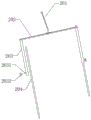
FIG. 1 is a schematic structural view of the present invention;
FIG. 2 is a perspective view of the main body of the apparatus of the present invention;
FIG. 3 is a schematic view of an adjustable stand according to the present invention;
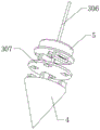
FIG. 4 is a structural diagram of the assembled measuring support bar of the present invention;
FIG. 5 is a block diagram of the nut sleeve of the present invention;
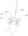
FIG. 6 is an exploded view of the clump weight and the surveying instrument of the present invention;
FIG. 7 is a structural diagram of a weight member of the present invention;
fig. 8 is a cross-sectional view of a square cartridge in accordance with the present invention.
In the figure: 1. a movable support seat; 101. an upper disc; 1011. a hemispherical limit cover; 102. a lower disc; 1021. a spherical limiting strip; 2. an adjustable support frame; 201. a main support bar; 202. a transverse plate; 203. a hollow tube; 2031. a nut seat; 2032. clamping the bolt; 204. a slide bar; 3. an assembled measuring support rod; 301. rotating the ball; 302. a first lightweight slim rod; 303. horizontal bubble; 304. a second lightweight slender rod; 305. a nut sleeve; 306. a docking rod; 307. mounting a disc; 3071. a square groove; 4. a balancing weight; 401. A square block; 4011. a locking hole; 5. a surveying instrument; 501. a base plate; 502. a square fixture block; 5021. a cylindrical groove; 503. a slider; 504. a spring; 505. a locking lever.
Detailed Description
Example 1:
the embodiment of the invention discloses a construction project cost on-site convenient adjustment and mapping device, as shown in figures 1-8, comprising:
the device comprises a movable supporting seat 1, adjustable supporting frames 2 are assembled on two sides of the movable supporting seat 1, an assembled measuring supporting rod 3 is movably connected to the movable supporting seat 1, and a balancing weight 4 and a surveying instrument 5 are arranged at the bottom of the assembled measuring supporting rod 3;
the movable supporting seat 1 comprises an upper disc 101 and a lower disc 102, the upper disc 101 and the lower disc 102 are fixed through bolts, the top of the upper disc 101 is fixedly connected with a hemispherical limiting cover 1011, and the bottom of the lower disc 102 is fixedly connected with a spherical limiting strip 1021;
the assembled measuring support rod 3 comprises a rotary ball 301, and the rotary ball 301 is rotatably connected between a hemispherical limit cover 1011 and a spherical limit strip 1021.
As a technical optimization scheme of the invention, the adjustable support frame 2 comprises a main support rod 201, the top of the main support rod 201 is fixedly connected to the bottom of the lower disc 102 through bolts, the bottom of the main support rod 201 is fixedly connected with a transverse plate 202, the bottom of the transverse plate 202 is fixedly connected with two groups of hollow tubes 203, the transverse plate 202 is arranged to support the two groups of hollow tubes 203, and the two groups of hollow tubes 203 are symmetrically distributed, so that the support effect on the main support rod 201 is good, that is, the support effect of the adjustable support frame 2 on the movable support base 1 is guaranteed to be good.
As a technical optimization scheme of the invention, a sliding rod 204 is connected in the tube cavity of the hollow tube 203 in a sliding manner, the bottom of the sliding rod 204 is provided with a tip, the side wall of the hollow tube 203 is fixedly connected with a nut seat 2031, the axis of the nut seat 2031 is in threaded connection with a clamping bolt 2032, the clamping bolt 2032 penetrates through the tube wall of the hollow tube 203 and abuts against the outer wall of the sliding rod 204, and the arranged clamping bolt 2032 is matched with the sliding rod 204, so that a user can conveniently adjust the supporting height of the whole movable supporting seat 1, the adjustment is simple and convenient to operate, time and labor are saved, the side wall of the sliding rod 204 is polished by using a coarse polishing piece, and the friction force is increased.
As a technical optimization scheme of the invention, the top of the rotating ball 301 is fixedly connected with the first light thin rod 302, the top of the first light thin rod 302 is fixedly connected with the horizontal bubble 303, and the combination of the first light thin rod 302 and the horizontal bubble 303 can ensure that the levelness of the whole device is monitored, the surveying instrument 5 is ensured to be in a horizontal state for measurement, and the data is ensured to be accurate.
As a technical optimization scheme of the invention, the bottom of the rotating ball 301 is fixedly connected with a second light thin rod 304, the bottom of the second light thin rod 304 is fixedly connected with a nut sleeve 305, the bottom of the nut sleeve 305 is in threaded connection with a butt joint rod 306, the bottom of the butt joint rod 306 is fixedly connected with a mounting disc 307, the mounting disc 307 is clamped and fixed between the clump weight 4 and the surveying instrument 5, and the butt joint rod 306 can be selected from different models and different lengths, so that different supporting heights of the surveying instrument 5 and the clump weight 4 can be realized.
When the portable light weight thin rod type portable light weight limiting device is used, the whole device body is convenient to disassemble and assemble, so that the portable light weight thin rod type portable light weight limiting device is convenient to carry, when the whole device is assembled, the second light weight thin rod 304 and the nut sleeve 305 are inserted downwards in alignment with the notches of the lower circular disc 102 and the spherical limiting strip 1021, the rotating ball 301 is clamped into the spherical limiting strip 1021, and at the moment, the upper circular disc 101 and the hemispherical limiting cover 1011 are sleeved on the first light weight thin rod 302 and the horizontal bulb 303 and are pressed downwards in alignment with the lower circular disc 102.
After the upper disc 101 and the lower disc 102 are in butt joint, the rotating ball 301 is limited by the bolts, and the adjustable support frame 2 is continuously installed and fixed at the moment.
When the adjustable support frame 2 is installed and fixed, firstly, the upper part of the main support rod 201 is fixed below the lower disc 102 by using bolts, then the lower part of the main support rod 201 is fixed with the transverse plate 202 by using bolts, and after the transverse plate 202 is fixed, the distance of the sliding rod 204 is adjusted, so that the support of the whole movable support seat 1 with different heights is realized.
When adjusting, at first unscrew chucking bolt 2032 for slide bar 204 can slide along the intracavity of hollow tube 203, and slide bar 204 is when sliding, and the most advanced of bottom contacts with ground, and the back is adjusted to the height-adjusting of whole slide bar 204, and is different to the support height of activity supporting seat 1, and after adjusting to suitable height, directly screw up chucking bolt 2032 this moment and carry out the chucking with the position of slide bar 204 and fix.
After the position with activity supporting seat 1 and adjustable support frame 2 is installed, fix balancing weight 4 and surveying instrument 5 at the lower extreme of assembled measurement bracing piece 3, fix promptly on mounting disc 307, then aim at the below of nut cover 305 with the top of butt joint pole 306 and screw up fixedly can accomplish the installation of whole device fixed, easy operation is convenient, is equipped with the screw thread that meshes mutually with nut cover 305 at the top of butt joint pole 306.
Working principle, when whole device is used, can adjust surveying instrument 5's supporting height, concrete utilization adjustable support frame 2 realizes, when using surveying instrument 5, can guarantee that surveying instrument 5 uses under the horizontality always, strengthen surveying instrument 5's accuracy, under the action of gravity, balancing weight 4 is the toper, its gravity that receives keeps vertical decurrent trend all the time, under the gravity pulling force of balancing weight 4, even whole movable supporting seat 1 and adjustable support frame 2 do not have the level to place on ground, its ball of revolution 301 owing to can rotate between hemisphere spacing cover 1011 and sphere spacing strip 1021, therefore under the action of gravity of balancing weight 4, make surveying instrument 5 receive this pulling force and keep the horizontality to measure, can monitor surveying instrument 5's levelness in real time through the first light pin 302 and the horizontal bubble 303 that set up, thereby ensuring the mapping effect.
Example 2:
the embodiment of the invention discloses a construction project cost on-site convenient adjustment and mapping device, as shown in figures 1-8, comprising:
the device comprises a movable supporting seat 1, adjustable supporting frames 2 are assembled on two sides of the movable supporting seat 1, an assembled measuring supporting rod 3 is movably connected to the movable supporting seat 1, and a balancing weight 4 and a surveying instrument 5 are arranged at the bottom of the assembled measuring supporting rod 3;
the movable supporting seat 1 comprises an upper disc 101 and a lower disc 102, the upper disc 101 and the lower disc 102 are fixed through bolts, the top of the upper disc 101 is fixedly connected with a hemispherical limiting cover 1011, and the bottom of the lower disc 102 is fixedly connected with a spherical limiting strip 1021;
assembled measurement bracing piece 3 includes swivel ball 301, and swivel ball 301 rotates to be connected between spacing cover 1011 of hemisphere and spherical spacing strip 1021, and the device's overall structure is simple, low in manufacturing cost, and the later stage is also convenient to be maintained to whole device equipment is convenient, also conveniently disassembles whole device and preserves when the later stage need not use, and the device is small after pulling down, conveniently carries and transports, occupation space not.
As a technical optimization scheme of the invention, four groups of square blocks 401 are fixedly connected to the top of the balancing weight 4, a bottom plate 501 is fixedly connected to the bottom of the surveying instrument 5, two groups of square fixture blocks 502 are fixedly connected to the bottom of the bottom plate 501, four groups of square grooves 3071 corresponding to the square blocks 401 are formed in the top of the mounting plate 307, the square blocks 401 are movably inserted into the square grooves 3071, the square fixture blocks 502 are movably clamped between the two groups of square blocks 401, the number of the arranged square fixture blocks 502 is two, and the number of the square blocks 401 is four, so that each group of square fixture blocks 502 are respectively clamped between two different groups of square blocks 401 to form fixation.
As a technical optimization scheme of the invention, the side wall of the square block 401 is provided with a locking hole 4011, the inside of the square block 502 is provided with a cylindrical groove 5021, the cylindrical groove 5021 is connected with two groups of sliders 503 in a sliding manner, a spring 504 is fixedly connected between the two groups of sliders 503, one side of the two groups of sliders 503 opposite to each other is fixedly connected with a locking rod 505, the locking rod 505 passes through the cylindrical groove 5021 and is movably inserted in the locking hole 4011, when the arranged locking rod 505 is inserted in the locking hole 4011, the insertion is stable, after the installation and the fixation of the surveying instrument 5 and the balancing weight 4 are carried out, the whole surveying instrument 5 and the balancing weight 4 are not easy to loosen, and the installation and the fixation effects are good.
As a technical optimization scheme of the invention, the spring 504 is in a compressed state, the side wall of the sliding block 503 is fixedly connected with a handle, the side wall of the square clamping block 502 is provided with a sliding groove corresponding to the handle on the sliding block 503, the handle of the sliding block 503 is slidably connected in the sliding groove of the square clamping block 502, and the arranged handle of the sliding block 503 is convenient for a user to push the sliding block 503 and the locking rod 505.
As a technical optimization scheme of the invention, the shape of the balancing weight 4 is conical, the shapes of the surveying instrument 5 and the bottom plate 501 are annular, the surveying instrument 5 and the bottom plate 501 are sleeved on the assembled measuring support rod 3, the weight of the arranged balancing weight 4 is large, the tension effect on the whole assembled measuring support rod 3 is large, so that the vertical state is kept, the surveying instrument 5 is annular, and the gravity center of the surveying instrument 5 is coincided with the vertical central line of the balancing weight 4.
When carrying out surveying instrument 5 and balancing weight 4's installation fixedly, the operation is simple and convenient, time saving and labor saving, it is fixed to realize synchronous installation, save time, at first aim at square groove 3071 with the square block 401 at balancing weight 4 top and insert, this moment, stimulate two sets of sliders 503, make slider 503 motion and extrusion spring 504, drive check lock lever 505 lateral sliding simultaneously, cup joint surveying instrument 5 and bottom plate 501 on nut cover 305 and butt joint pole 306 this moment, and make square fixture block 502 joint between square block 401, then loosen hand slider 503, under spring 504's spring action, spring 504 promotes slider 503 lateral sliding and drives check lock lever 505 and pop out, insert check lock lever 505 in locking hole 4011, form the installation fixed to balancing weight 4 and surveying instrument 5, the installation is fixed simple and convenient, the later stage is also conveniently dismantled, satisfy the user's demand.
The foregoing shows and describes the general principles and broad features of the present invention and advantages thereof. It will be understood by those skilled in the art that the present invention is not limited to the embodiments described above, which are described in the specification and illustrated only to illustrate the principle of the present invention, but that various changes and modifications may be made therein without departing from the spirit and scope of the present invention, which fall within the scope of the invention as claimed. The scope of the invention is defined by the appended claims and equivalents thereof.
Claims (9)
1. The utility model provides a surveying and mapping device is adjusted to building engineering cost is on-spot convenient, its characterized in that includes:
the device comprises a movable supporting seat (1), wherein adjustable supporting frames (2) are assembled on two sides of the movable supporting seat (1), an assembled measuring supporting rod (3) is movably connected to the movable supporting seat (1), and a balancing weight (4) and a surveying instrument (5) are arranged at the bottom of the assembled measuring supporting rod (3);
the movable supporting seat (1) comprises an upper disc (101) and a lower disc (102), the upper disc (101) and the lower disc (102) are fixed through bolts, the top of the upper disc (101) is fixedly connected with a hemispherical limiting cover (1011), and the bottom of the lower disc (102) is fixedly connected with a spherical limiting strip (1021);
assembled measurement bracing piece (3) are including swivel ball (301), swivel ball (301) are rotated and are connected between spacing cover of hemisphere (1011) and spherical spacing strip (1021).
2. The construction cost on-site convenient adjustment and mapping device of claim 1, wherein: the adjustable support frame (2) comprises a main support rod (201), the top of the main support rod (201) is fixedly connected to the bottom of the lower disc (102) through bolts, a transverse plate (202) is fixedly connected to the bottom of the main support rod (201), and two groups of hollow tubes (203) are fixedly connected to the bottom of the transverse plate (202).
3. The construction cost on-site convenient adjustment and mapping device of claim 2, wherein: the pipe cavity of the hollow pipe (203) is connected with a sliding rod (204) in a sliding mode, the bottom of the sliding rod (204) is provided with a tip, the side wall of the hollow pipe (203) is fixedly connected with a nut seat (2031), the axis of the nut seat (2031) is in threaded connection with a clamping bolt (2032), and the clamping bolt (2032) penetrates through the pipe wall of the hollow pipe (203) and abuts against the outer wall of the sliding rod (204).
4. The construction cost on-site convenient adjustment and mapping device of claim 1, wherein: the top of the rotating ball (301) is fixedly connected with a first light thin rod (302), and the top of the first light thin rod (302) is fixedly connected with a horizontal bubble (303).
5. The construction cost on-site convenient adjustment and mapping device of claim 1, wherein: the bottom fixedly connected with second light slender rod (304) of rotatory ball (301), the bottom fixedly connected with nut cover (305) of second light slender rod (304), the bottom threaded connection of nut cover (305) has butt joint pole (306), the bottom fixedly connected with mounting disc (307) of butt joint pole (306), mounting disc (307) are pressed from both sides tightly and are fixed between balancing weight (4) and surveying instrument (5).
6. The construction cost on-site convenient adjustment and mapping device according to claim 5, wherein: the top fixedly connected with four square blocks (401) of balancing weight (4), bottom fixedly connected with bottom plate (501) of surveying instrument (5), two sets of square fixture block (502) of bottom plate (501) fixedly connected with, four sets of square groove (3071) that correspond with square block (401) position are seted up at the top of mounting disc (307), square block (401) activity is pegged graft in square groove (3071), square fixture block (502) activity joint is between two sets of square blocks (401).
7. The construction cost on-site convenient adjustment and mapping device of claim 6, wherein: the locking hole (4011) has been seted up to the lateral wall of square piece (401), cylinder groove (5021) have been seted up to the inside of square fixture block (502), sliding connection has two sets of sliders (503) in cylinder groove (5021), and is two sets of fixedly connected with spring (504) between slider (503), and is two sets of one side fixedly connected with lock lever (505) that slider (503) are opposite, lock lever (505) pass cylinder groove (5021) and the activity is pegged graft in locking hole (4011).
8. The construction cost on-site convenient adjustment and mapping device according to claim 7, wherein: the spring (504) is in a compressed state, a handle is fixedly connected to the side wall of the sliding block (503), a sliding groove corresponding to the handle on the sliding block (503) is formed in the side wall of the square clamping block (502), and the handle of the sliding block (503) is slidably connected into the sliding groove of the square clamping block (502).
9. The construction cost on-site convenient adjustment and mapping device of claim 6, wherein: the shape of balancing weight (4) is the toper, the shape of surveying instrument (5) and bottom plate (501) is the annular, surveying instrument (5) and bottom plate (501) cup joint on assembled measurement bracing piece (3).
Priority Applications (1)
| Application Number | Priority Date | Filing Date | Title |
|---|---|---|---|
| CN202110578890.4A CN113252016B (en) | 2021-05-26 | 2021-05-26 | Convenient on-spot regulation mapping device of building engineering cost |
Applications Claiming Priority (1)
| Application Number | Priority Date | Filing Date | Title |
|---|---|---|---|
| CN202110578890.4A CN113252016B (en) | 2021-05-26 | 2021-05-26 | Convenient on-spot regulation mapping device of building engineering cost |
Publications (2)
| Publication Number | Publication Date |
|---|---|
| CN113252016A true CN113252016A (en) | 2021-08-13 |
| CN113252016B CN113252016B (en) | 2023-06-16 |
Family
ID=77184604
Family Applications (1)
| Application Number | Title | Priority Date | Filing Date |
|---|---|---|---|
| CN202110578890.4A Active CN113252016B (en) | 2021-05-26 | 2021-05-26 | Convenient on-spot regulation mapping device of building engineering cost |
Country Status (1)
| Country | Link |
|---|---|
| CN (1) | CN113252016B (en) |
Cited By (4)
| Publication number | Priority date | Publication date | Assignee | Title |
|---|---|---|---|---|
| CN114321615A (en) * | 2022-01-19 | 2022-04-12 | 熊燕燕 | Geotechnical engineering reconnaissance is with firm eyelidretractor that has automatic horizontal function that keeps |
| CN114542914A (en) * | 2022-03-02 | 2022-05-27 | 河南理工大学 | Adjustable supporting device for surveying instrument |
| CN115046082A (en) * | 2022-05-20 | 2022-09-13 | 浙江同信工程项目管理有限公司 | On-spot mapping device of building engineering cost |
| CN116222337A (en) * | 2023-05-05 | 2023-06-06 | 天津宇昊建筑工程检测有限公司 | Mapping device for building structure design and application method thereof |
Citations (5)
| Publication number | Priority date | Publication date | Assignee | Title |
|---|---|---|---|---|
| JP2009036700A (en) * | 2007-08-03 | 2009-02-19 | Audio Technica Corp | Tripod adapter for marking apparatus |
| CN205785270U (en) * | 2016-05-17 | 2016-12-07 | 福建省速卖通电子商务有限公司 | A kind of surveying instrument supporting frame |
| CN108613693A (en) * | 2018-04-25 | 2018-10-02 | 合肥上城信息技术有限公司 | A kind of multi-angle regulation mounting bracket for measurement and control instrument |
| CN208171311U (en) * | 2018-05-07 | 2018-11-30 | 邵阳学院 | A kind of civil engineering portable surveying instrument support device |
| CN209399991U (en) * | 2019-03-25 | 2019-09-17 | 龚小虎 | A kind of portable surveying instrument of engineering mapping gravity-center adjustable |
-
2021
- 2021-05-26 CN CN202110578890.4A patent/CN113252016B/en active Active
Patent Citations (5)
| Publication number | Priority date | Publication date | Assignee | Title |
|---|---|---|---|---|
| JP2009036700A (en) * | 2007-08-03 | 2009-02-19 | Audio Technica Corp | Tripod adapter for marking apparatus |
| CN205785270U (en) * | 2016-05-17 | 2016-12-07 | 福建省速卖通电子商务有限公司 | A kind of surveying instrument supporting frame |
| CN108613693A (en) * | 2018-04-25 | 2018-10-02 | 合肥上城信息技术有限公司 | A kind of multi-angle regulation mounting bracket for measurement and control instrument |
| CN208171311U (en) * | 2018-05-07 | 2018-11-30 | 邵阳学院 | A kind of civil engineering portable surveying instrument support device |
| CN209399991U (en) * | 2019-03-25 | 2019-09-17 | 龚小虎 | A kind of portable surveying instrument of engineering mapping gravity-center adjustable |
Cited By (7)
| Publication number | Priority date | Publication date | Assignee | Title |
|---|---|---|---|---|
| CN114321615A (en) * | 2022-01-19 | 2022-04-12 | 熊燕燕 | Geotechnical engineering reconnaissance is with firm eyelidretractor that has automatic horizontal function that keeps |
| CN114321615B (en) * | 2022-01-19 | 2024-01-12 | 西安市鸿儒岩土科技开发有限公司 | Stable support with automatic horizontal maintaining function for geotechnical engineering investigation |
| CN114542914A (en) * | 2022-03-02 | 2022-05-27 | 河南理工大学 | Adjustable supporting device for surveying instrument |
| CN114542914B (en) * | 2022-03-02 | 2023-04-25 | 河南理工大学 | Adjustable supporting device for surveying instrument |
| CN115046082A (en) * | 2022-05-20 | 2022-09-13 | 浙江同信工程项目管理有限公司 | On-spot mapping device of building engineering cost |
| CN116222337A (en) * | 2023-05-05 | 2023-06-06 | 天津宇昊建筑工程检测有限公司 | Mapping device for building structure design and application method thereof |
| CN116222337B (en) * | 2023-05-05 | 2023-07-25 | 天津宇昊建筑工程检测有限公司 | Mapping device for building structure design and application method thereof |
Also Published As
| Publication number | Publication date |
|---|---|
| CN113252016B (en) | 2023-06-16 |
Similar Documents
| Publication | Publication Date | Title |
|---|---|---|
| CN113252016A (en) | On-spot convenient surveying and mapping device that adjusts of building engineering cost | |
| CN214368851U (en) | Surveying instrument positioner for surveying and mapping engineering | |
| CN212226582U (en) | Survey and drawing auxiliary assembly for urban ground construction engineering | |
| CN215596936U (en) | On-spot mapping device of building engineering cost | |
| CN212107605U (en) | Auxiliary marker post for coal mine drilling | |
| CN217684228U (en) | Tester for urban and rural building planning | |
| CN110823174A (en) | Sopwith staff fixing device is used in survey and drawing | |
| CN212721429U (en) | Device convenient to engineering measuring instrument centering | |
| CN211667508U (en) | Level gauge for supervision of constructional engineering | |
| CN218002521U (en) | Level measurer | |
| CN214372457U (en) | Construction mapping device | |
| CN219038012U (en) | Survey and drawing data acquisition device | |
| CN212430341U (en) | Novel engineering measurement is with horizontal calibration device | |
| CN219221892U (en) | Level gauge suitable for various field uneven ground | |
| CN219933452U (en) | Surveying instrument positioning device for land surveying | |
| CN219623692U (en) | Level gauge for horizontal calibration | |
| CN216344928U (en) | Distance measuring device for building engineering | |
| CN214537951U (en) | Three-dimensional geological mapping equipment in city | |
| CN220851322U (en) | Road and bridge concrete structure monitoring devices | |
| CN216483036U (en) | Fixing base for total powerstation | |
| CN219414294U (en) | Engineering survey and drawing sign positioning equipment | |
| CN203232668U (en) | Upright rod angle adjuster of roll screen | |
| CN215335434U (en) | High-precision geodetic leveling instrument | |
| CN219673826U (en) | Portable mapping device for constructional engineering specialty | |
| CN220688571U (en) | Surveying instrument fixing device for complex topography |
Legal Events
| Date | Code | Title | Description |
|---|---|---|---|
| PB01 | Publication | ||
| PB01 | Publication | ||
| SE01 | Entry into force of request for substantive examination | ||
| SE01 | Entry into force of request for substantive examination | ||
| GR01 | Patent grant | ||
| GR01 | Patent grant | ||
| TR01 | Transfer of patent right | ||
| TR01 | Transfer of patent right |
Effective date of registration: 20231113 Address after: Room 2020, Financial Center Office Building, High tech Zone, Xiangxi Tujia and Miao Autonomous Prefecture, Hunan Province, 416000 Patentee after: Hunan Darui Engineering Project Management Co.,Ltd. Address before: 471003 No. 404, door 4, building 8, No. 8 neighborhood, Jianxi District, Luoyang City, Henan Province Patentee before: Cheng Congrong |