CN113244679A - Environment-friendly solid-liquid separation equipment for chemical industry - Google Patents
Environment-friendly solid-liquid separation equipment for chemical industry Download PDFInfo
- Publication number
- CN113244679A CN113244679A CN202110652637.9A CN202110652637A CN113244679A CN 113244679 A CN113244679 A CN 113244679A CN 202110652637 A CN202110652637 A CN 202110652637A CN 113244679 A CN113244679 A CN 113244679A
- Authority
- CN
- China
- Prior art keywords
- box
- filter
- cleaning
- guide rail
- rod
- Prior art date
- Legal status (The legal status is an assumption and is not a legal conclusion. Google has not performed a legal analysis and makes no representation as to the accuracy of the status listed.)
- Withdrawn
Links
- 239000007788 liquid Substances 0.000 title claims abstract description 22
- 239000000126 substance Substances 0.000 title claims abstract description 22
- 238000000926 separation method Methods 0.000 title claims abstract description 18
- 238000004140 cleaning Methods 0.000 claims abstract description 114
- 239000007787 solid Substances 0.000 claims abstract description 43
- XLYOFNOQVPJJNP-UHFFFAOYSA-N water Substances O XLYOFNOQVPJJNP-UHFFFAOYSA-N 0.000 claims abstract description 34
- 238000007790 scraping Methods 0.000 claims description 56
- 238000005096 rolling process Methods 0.000 claims description 28
- 241000220317 Rosa Species 0.000 claims description 27
- 238000001914 filtration Methods 0.000 claims description 7
- 238000007599 discharging Methods 0.000 abstract 2
- 239000002351 wastewater Substances 0.000 description 19
- 238000000034 method Methods 0.000 description 11
- 230000008569 process Effects 0.000 description 7
- 238000003825 pressing Methods 0.000 description 6
- 230000009471 action Effects 0.000 description 5
- 239000012141 concentrate Substances 0.000 description 3
- 239000000463 material Substances 0.000 description 3
- 230000001360 synchronised effect Effects 0.000 description 3
- 239000002894 chemical waste Substances 0.000 description 2
- 238000010586 diagram Methods 0.000 description 2
- 238000010079 rubber tapping Methods 0.000 description 2
- 238000005406 washing Methods 0.000 description 2
- 239000002699 waste material Substances 0.000 description 2
- 238000009825 accumulation Methods 0.000 description 1
- 238000012271 agricultural production Methods 0.000 description 1
- 230000009286 beneficial effect Effects 0.000 description 1
- 230000008859 change Effects 0.000 description 1
- 238000012824 chemical production Methods 0.000 description 1
- 230000006835 compression Effects 0.000 description 1
- 238000007906 compression Methods 0.000 description 1
- 239000000498 cooling water Substances 0.000 description 1
- 230000000694 effects Effects 0.000 description 1
- 230000036541 health Effects 0.000 description 1
- 239000012535 impurity Substances 0.000 description 1
- 238000009776 industrial production Methods 0.000 description 1
- 238000012986 modification Methods 0.000 description 1
- 230000004048 modification Effects 0.000 description 1
- 230000000704 physical effect Effects 0.000 description 1
- 230000000452 restraining effect Effects 0.000 description 1
- 239000002912 waste gas Substances 0.000 description 1
Images


Classifications
-
- B—PERFORMING OPERATIONS; TRANSPORTING
- B01—PHYSICAL OR CHEMICAL PROCESSES OR APPARATUS IN GENERAL
- B01D—SEPARATION
- B01D29/00—Filters with filtering elements stationary during filtration, e.g. pressure or suction filters, not covered by groups B01D24/00 - B01D27/00; Filtering elements therefor
- B01D29/50—Filters with filtering elements stationary during filtration, e.g. pressure or suction filters, not covered by groups B01D24/00 - B01D27/00; Filtering elements therefor with multiple filtering elements, characterised by their mutual disposition
- B01D29/52—Filters with filtering elements stationary during filtration, e.g. pressure or suction filters, not covered by groups B01D24/00 - B01D27/00; Filtering elements therefor with multiple filtering elements, characterised by their mutual disposition in parallel connection
-
- B—PERFORMING OPERATIONS; TRANSPORTING
- B01—PHYSICAL OR CHEMICAL PROCESSES OR APPARATUS IN GENERAL
- B01D—SEPARATION
- B01D29/00—Filters with filtering elements stationary during filtration, e.g. pressure or suction filters, not covered by groups B01D24/00 - B01D27/00; Filtering elements therefor
- B01D29/01—Filters with filtering elements stationary during filtration, e.g. pressure or suction filters, not covered by groups B01D24/00 - B01D27/00; Filtering elements therefor with flat filtering elements
- B01D29/014—Filters with filtering elements stationary during filtration, e.g. pressure or suction filters, not covered by groups B01D24/00 - B01D27/00; Filtering elements therefor with flat filtering elements with curved filtering elements
-
- B—PERFORMING OPERATIONS; TRANSPORTING
- B01—PHYSICAL OR CHEMICAL PROCESSES OR APPARATUS IN GENERAL
- B01D—SEPARATION
- B01D29/00—Filters with filtering elements stationary during filtration, e.g. pressure or suction filters, not covered by groups B01D24/00 - B01D27/00; Filtering elements therefor
- B01D29/62—Regenerating the filter material in the filter
- B01D29/64—Regenerating the filter material in the filter by scrapers, brushes, nozzles, or the like, acting on the cake side of the filtering element
- B01D29/6407—Regenerating the filter material in the filter by scrapers, brushes, nozzles, or the like, acting on the cake side of the filtering element brushes
- B01D29/6415—Regenerating the filter material in the filter by scrapers, brushes, nozzles, or the like, acting on the cake side of the filtering element brushes with a rotary movement with respect to the filtering element
-
- B—PERFORMING OPERATIONS; TRANSPORTING
- B01—PHYSICAL OR CHEMICAL PROCESSES OR APPARATUS IN GENERAL
- B01D—SEPARATION
- B01D29/00—Filters with filtering elements stationary during filtration, e.g. pressure or suction filters, not covered by groups B01D24/00 - B01D27/00; Filtering elements therefor
- B01D29/88—Filters with filtering elements stationary during filtration, e.g. pressure or suction filters, not covered by groups B01D24/00 - B01D27/00; Filtering elements therefor having feed or discharge devices
- B01D29/94—Filters with filtering elements stationary during filtration, e.g. pressure or suction filters, not covered by groups B01D24/00 - B01D27/00; Filtering elements therefor having feed or discharge devices for discharging the filter cake, e.g. chutes
Abstract
The invention discloses an environment-friendly chemical solid-liquid separation device in the technical field of solid-liquid separation devices, which comprises a plurality of filter boxes, wherein the filter boxes are arranged side by side, a filter plate is arranged in the middle of each filter box, the filter plate is an arc-shaped plate, and part of space of each filter box above the filter plate is in a fan shape; a water inlet hole is formed in the upper portion of the left side of the filter box, a water discharging hole is formed in the lower portion of the right side of the filter box, a slope is formed in the lower end of the filter box, and the lower end of the slope is located on one side of the water discharging hole; a cleaning device for cleaning solid matters on the filter plate is erected above the filter box, and a knocking device for assisting the cleaning device to shake off the solid matters is arranged on the left side of the filter box; when the solid matter on the filter plate accumulates to a certain degree, the filter plate does not need to be replaced by cleaning device, the operation is simple and safe, and the solid matter in the cleaning device is shaken off by the cooperation of the cleaning device and the cleaning device.
Description
Technical Field
The invention relates to the technical field of solid-liquid separation equipment, in particular to environment-friendly chemical solid-liquid separation equipment.
Background
The original physical property or chemical property of the pure water is changed after the pure water is used, and the pure water becomes wastewater containing different impurities. The chemical wastewater is the wastewater such as process wastewater, cooling water, waste gas washing water, equipment and site washing water and the like discharged in chemical production. If the waste water is discharged without treatment, the waste water can cause pollution of different properties and different degrees of water bodies, thereby harming human health and influencing industrial and agricultural production.
In the chemical waste liquid treatment process, solid-liquid separation is firstly carried out, solid matters in the waste liquid are firstly intercepted and filtered, and the waste liquid treatment efficiency is improved. However, after the existing solid-liquid separation equipment is used for a period of time, a large amount of solid matters are accumulated on the filter screen, and the solid matters occupy the filtering space, block the filter screen and reduce the filtering efficiency; the common method is to jack up and replace the filter screen, and the process of replacing the filter screen is not only complicated, but also has to prevent chemical waste liquid from polluting human bodies, and has certain danger.
Based on the technical scheme, the invention designs the environment-friendly chemical solid-liquid separation equipment to solve the problems.
Disclosure of Invention
In order to solve the above problems, the present invention provides the following technical solutions:
the environment-friendly chemical solid-liquid separation equipment comprises a plurality of filter boxes, wherein the filter boxes are arranged side by side, a filter plate is arranged in the middle of each filter box and is an arc-shaped plate, and part of space of each filter box above the corresponding filter plate is in a fan shape; the upper part of the left side of the filter box is provided with a water inlet, the lower part of the right side of the filter box is provided with a water outlet, the lower end of the filter box is provided with a slope, and the lower end of the slope is positioned on one side of the water outlet; the filter box is characterized in that a cleaning device for cleaning solid matters on the filter plate is erected above the filter box, and a knocking device for assisting the cleaning device to shake off the solid matters is arranged on the left side of the filter box.
During the use, the accessible inlet opening pours into chemical industry waste water into the rose box, and waste water can pass the filter and get into the rose box lower part to discharge from the wash port through slope water conservancy diversion finally. When the wastewater passes through the filter plate, large granular solid matters are trapped by the filter plate and deposited on the filter plate. When the solid matters on the filter plate are accumulated to a certain degree, the solid matters in the cleaning device can be cleaned through the cleaning device and shaken off through the cooperation of the cleaning device and the cleaning device.
As a further scheme of the invention, the cleaning device comprises cleaning brushes and cleaning scraping boxes, the cleaning brushes and the cleaning scraping boxes are uniformly distributed around the rotating shaft in a circumferential mode, the three cleaning brushes and the three cleaning scraping boxes form a group, the cleaning brushes and the cleaning scraping boxes in the same group are distributed at intervals, and each group of the cleaning brushes and the cleaning scraping boxes is matched with one filter box for use.
As a further scheme of the invention, the upper end of the side wall of the filter box is fixedly connected with a bearing plate, the rotating shaft is rotatably connected to the upper end of the bearing plate, one end of the rotating shaft is fixedly connected with a crank, and the cleaning brush is fixedly installed with the rotating shaft through a connecting plate.
Shaking the crank and can driving the pivot and rotate, and then driving the clearance brush and scrape the synchronous rotation of box with the clearance, the clearance brush scrapes the box in advance in the clearance and gets into the rose box when rotating, and the clearance brush can concentrate the solid matter of homodisperse on the filter together rotating the in-process to finally clear out the rose box.
As a further scheme of the invention, the cleaning scraping boxes in the same row in different groups are fixedly connected with the same sliding rod through a connecting plate, the sliding rod is connected to one end of a rod seat in a sliding manner, one end of the sliding rod is provided with a limiting ring, the other end of the sliding rod is fixedly connected with a rolling ball, the other end of the rod seat is fixedly connected with a rotating shaft, the sliding rod is a regular hexagonal rod, one end of the rod seat is provided with a regular hexagonal hole, and one surface of the regular hexagonal hole is coplanar with the end surface of the rod seat; the bottom end of the cleaning scraping box is provided with a water filtering hole, and the front end of one surface of the cleaning scraping box, which is contacted with the filter plate when the cleaning scraping box rotates, is provided with a collecting knife.
When the pivot is rotatory, can drive the pole socket and rotate, can drive the slide bar when the pole socket rotates and rotate, and then drive the clearance and scrape the box and rotate, the box is scraped in the clearance and gets into the rose box at the clearance brush back, collect the solid matter that the sword will not be cleared away by the clearance brush and hang into the clearance and scrape in the box, the box is scraped in the clearance when removing, water can pass the drainage hole, reduces the resistance on the one hand, on the other hand prevents that the clearance from scraping the box and stores up a large amount of water when leaving the rose box. Regular hexagon pole and regular hexagon shape hole cooperation prevent that the slide bar from sliding for the pole socket when guaranteeing that the slide bar can slide in regular hexagon shape hole, when the slide bar slides, connect the connecting plate that the box was scraped in the clearance moreover and can not interfere with pole socket each other.
As a further scheme of the invention, a group of the rod seats is fixedly connected with a restraint rod, a press plate is connected outside the restraint rod in a sliding mode, the press plate is fixedly connected with the sliding rod, a spring is sleeved outside the restraint rod and positioned between the press plate and the rod seats, the rod seats cannot be a group close to the crank, and the length of the sliding rod can be reduced to a certain extent.
As a further scheme of the invention, the filter box positioned on one side of the crank is provided with a space guide rail through a bracket, the space guide rail comprises a push-out guide rail, a push-keeping guide rail, a return guide rail and a push-keeping guide rail, the projection of the space guide rail is a circular ring, and the rolling ball is in top contact with the space guide rail.
Along with the rotation of crank, the box can be located different positions to the box is scraped in the clearance, and the spin can be in the different positions of space guide rail to the spin just gets into to keep returning the guide rail as the example and explains. The rocking handle is rocked, the rolling ball moves along the circular motion of the return guide rail seat, in the period, the return guide rail is kept parallel to the rotation plane of the rocking handle on the plane, namely the front position and the rear position are unchanged, the front position and the rear position are front positions and the position far away from the rocking handle is rear positions), so the rolling ball can not push the sliding rod to slide, and the spring is in a slightly compressed state at the moment, so the relative position relation of the sliding rod and the rod seat is stable. When the spin slides by keeping returning the guide rail and sliding to the release guide rail, the box just leaves the rose box just to the clearance that corresponds, because release guide rail initial end moves backward gradually to the terminal in the pivot direction, so when the spin slides on releasing the slide rail, can promote the slide bar and slide backward along the rod seat, make clamp plate compression spring, the slide bar can drive its fixed connection's clearance on it and scrape the box and deviate the rose box gradually, when the spin is about to move to release guide rail terminal, the box completely skew rose box is scraped in the clearance. When the rolling ball moves from the push-out guide rail to the push-out guide rail, the cleaning scraping box is just vertical, the opening of the cleaning scraping box faces downwards when the rolling ball continues to rotate, solid substances in the cleaning scraping box are poured on the ground or in a collecting box arranged on the ground, and the cleaning scraping box cannot move back and forth in the process. When the spin is about to remove to keeping pushing out the guide rail terminal, the opening that the box was scraped in the clearance is downward completely, and accessible knocking device is scraped the box to the clearance and is strikeed this moment, makes the box body produce the vibration, shakes off the solid matter in the box body completely. When the spin is by keeping releasing the guide rail and getting into the guide rail that returns, along with the spin removes to and restore to the spring under the spring action of deformation, the slide bar moves forward gradually and resets, and then drives the clearance and scrapes the box and reset, when the spin removes to keeping returning when the slide rail initial end, the box is scraped to slide bar and clearance and resets completely, the box just is located rose box left side top is scraped in the clearance this moment, continue to rotate, then the clearance is scraped the box and is got into the solid matter of rose box on to the filter and clear up.
As a further scheme of the invention, the knocking device comprises upright columns, the number of the upright columns is the same as that of the filter boxes, the upper parts of the upright columns are rotatably connected with knocking rods, one ends of the knocking rods are fixedly connected with knocking balls, the upper parts of the knocking rods are fixedly connected with elastic ropes, and the other ends of the elastic ropes penetrate through the upright columns and are fixedly connected with the other sides of the upright columns; the lower end of the upright post is provided with a convex groove, a pedal is connected in the convex groove in a sliding mode, a pull rope is arranged between the pedal and the knocking rod, and the pull rope is not elastic.
When the opening of scraping the box in the clearance was downward completely, trampled the footboard, the footboard slided downwards along the convex groove, drove the resistance that strikes the pole and overcome the elastic cord through the stay cord and rotates downwards, strikes the ball and can strike the clearance with higher speed and scrape the box, makes the box body produce the vibration, and then shakes off the solid matter in the box. The pedal is released, and the knocking rod and the knocking ball are reset under the action of the elastic rope.
Advantageous effects
Compared with the prior art, the invention has the beneficial effects that:
1. chemical wastewater is injected into the filter box through the water inlet hole, and the wastewater can pass through the filter plate to enter the lower part of the filter box and is finally discharged from the water outlet hole through slope diversion. When the wastewater passes through the filter plate, large granular solid matters are trapped by the filter plate and deposited on the filter plate. When the solid matter on the filter plate accumulates to a certain degree, the filter plate does not need to be replaced by cleaning device, the operation is simple and safe, and the solid matter in the cleaning device is shaken off by the cooperation of the cleaning device and the cleaning device.
2. Through the cooperation of cleaning device and space guide rail, make the clearance scrape the box and empty away the solid matter outside the rose box, avoid falling into the rose box inside from the material of empting in the box body.
Drawings
In order to more clearly illustrate the technical solutions of the embodiments of the present invention, the drawings used in the description of the embodiments will be briefly introduced below, and it is obvious that the drawings in the following description are only some embodiments of the present invention, and it is obvious for those skilled in the art that other drawings can be obtained according to the drawings without creative efforts.
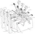
FIG. 1 is a schematic diagram of the overall structure of the present invention;
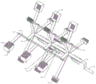
FIG. 2 is a schematic view of the structure of the cleaning device, the filter box and the space guide rail of the present invention;
FIG. 3 is a schematic right-view structural diagram of FIG. 2 in accordance with the present invention;
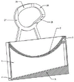
FIG. 4 is a schematic structural view of a cleaning apparatus according to the present invention;
FIG. 5 is a schematic cross-sectional view of the space rail and the filter box of the present invention;
FIG. 6 is a schematic view of the knocking device according to the present invention.
In the drawings, the components represented by the respective reference numerals are listed below:
1-a filter box, 2-a filter plate, 3-a water inlet, 4-a water outlet, 5-a slope, 6-a cleaning device, 7-a knocking device, 8-a cleaning brush, 9-a cleaning scraping box, 10-a bearing plate, 11-a rotating shaft, 12-a crank, 13-a sliding rod, 14-a rod seat, 15-a spacing ring, 16-a rolling ball, 17-a regular hexagon hole, 18-a water filtering hole, 19-a collecting knife, 20-a restraining rod, 21-a pressing plate, 22-a spring, 23-a space guide rail, 24-a pushing guide rail, 25-a keeping pushing guide rail, 26-a returning guide rail, 27-a keeping returning guide rail, 28-a stand column, 29-a knocking rod, 30-a hitting knocking rod, 31-an elastic rope and 32-a pedal, 33-pulling the rope.
Detailed Description
The technical solutions in the embodiments of the present invention will be clearly and completely described below with reference to the drawings in the embodiments of the present invention, and it is obvious that the described embodiments are only a part of the embodiments of the present invention, and not all of the embodiments. All other embodiments, which can be derived by a person skilled in the art from the embodiments given herein without making any creative effort, shall fall within the protection scope of the present invention.
Referring to fig. 1-6, the present invention provides a technical solution:
an environment-friendly chemical solid-liquid separation device is shown in figures 1, 2 and 6 and comprises a plurality of filter boxes 1, wherein the filter boxes 1 are arranged side by side, a filter plate 2 is arranged in the middle of each filter box 1, each filter plate 2 is an arc-shaped plate, and part of space of each filter box 1 above the corresponding filter plate 2 is in a fan shape; a water inlet hole 3 is formed in the upper portion of the left side of the filter box 1, a water drain hole 4 is formed in the lower portion of the right side of the filter box 1, a slope 5 is arranged at the lower end of the filter box 1, and the lower end of the slope 5 is located on one side of the water drain hole 4; a cleaning device 6 for cleaning solid matters on the filter plate 2 is erected above the filter box 1, and a knocking device 7 for assisting the cleaning device 6 to shake off the solid matters is arranged on the left side of the filter box 1.
During the use, accessible inlet opening 3 pours into chemical industry waste water into rose box 1 into, and waste water can pass filter 2 and get into rose box 1 lower part to discharge from wash port 4 through slope 5 water conservancy diversion finally. When the wastewater passes through the filter plate 2, large granular solid matters are trapped by the filter plate 2 and deposited on the filter plate 2. When the solid matter on the filter plate 2 is accumulated to a certain degree, the solid matter in the cleaning device 6 can be cleaned through the cleaning device 6 and shaken off through the cooperation of the device.
As an embodiment of the present invention, as shown in fig. 4, 3 and 2, the cleaning device 6 includes a cleaning brush 8 and a cleaning scraping box 9, the cleaning brush 8 and the cleaning scraping box 9 are circumferentially and uniformly distributed around the rotating shaft 11, and the three cleaning brushes 8 and the three cleaning scraping boxes 9 are in a group, the cleaning brushes 8 and the cleaning scraping boxes 9 in the same group are distributed at intervals, and each group of the cleaning brushes 8 and the cleaning scraping boxes 9 is used in cooperation with one filter box 1.
As an implementation mode of the invention, the upper end of the side wall of the filter box 1 is fixedly connected with a bearing plate 10, a rotating shaft 11 is rotatably connected to the upper end of the bearing plate 10, one end of the rotating shaft 11 is fixedly connected with a crank 12, and a cleaning brush 8 is fixedly installed with the rotating shaft 11 through a connecting plate.
Shaking crank 12 and can driving pivot 11 and rotating, and then driving cleaning brush 8 and the synchronous rotation of box 9 is scraped in the clearance, cleaning brush 8 scrapes box 9 earlier than the clearance and gets into rose box 1 when rotating, and cleaning brush 8 can concentrate the solid matter of homodisperse on filter 2 together rotating the in-process to finally clear out the rose box.
As an embodiment of the invention, as shown in fig. 4, 3 and 2, the cleaning scraping boxes 9 in the same row in different groups are all fixedly connected with the same slide bar 13 through a connecting plate, the slide bar 13 is slidably connected at one end of a bar seat 14, one end of the slide bar 13 is provided with a spacing ring 15, the other end of the slide bar 13 is fixedly connected with a rolling ball 16, the other end of the bar seat 14 is fixedly connected with a rotating shaft 11, the slide bar 13 is a regular hexagonal bar, one end of the bar seat 14 is provided with a regular hexagonal hole 17, and one surface of the regular hexagonal hole 17 is coplanar with the end surface of the bar seat 14; the bottom end of the cleaning scraping box 9 is provided with a water filtering hole 18, and the front end of one surface of the cleaning scraping box 9, which is contacted with the filter plate 2 when rotating, is provided with a collecting knife 19.
When pivot 11 is rotatory, can drive rod seat 14 and rotate, rod seat 14 can drive slide bar 13 and rotate when rotating, and then drive the clearance and scrape box 9 and rotate, the clearance is scraped box 9 and is got into rose box 1 behind clearance brush 8, collect the solid matter that sword 19 will not be cleared away by clearance brush 8 and hang into the clearance and scrape in the box 9, the box 9 is scraped in the clearance when removing, water can pass drainage hole 18, the resistance is reduced on the one hand, on the other hand prevents that the clearance from scraping box 9 and stores up a large amount of water when leaving rose box 1. The regular hexagon pole and the cooperation of regular hexagon hole 17 prevent that slide bar 13 from sliding for rod seat 14 when guaranteeing that slide bar 13 can slide in regular hexagon hole 17, and when slide bar 13 slided, the connecting plate of connecting box 9 is scraped in the clearance can not interfere with rod seat 14 each other moreover.
As an embodiment of the invention, as shown in FIG. 4, a group of rod holders 14 is fixedly connected with a restraint rod 20, the restraint rod 20 is externally connected with a pressing plate 21 in a sliding manner, the pressing plate 21 is fixedly connected with the sliding rod 13, a spring 22 is sleeved outside the restraint rod 20, the spring 22 is positioned between the pressing plate 21 and the rod holder 14, the rod holder 14 cannot be a group close to the crank 12, and the length of the sliding rod 13 can be reduced to a certain extent.
As shown in fig. 2, 3 and 5, as one embodiment of the present invention, a space rail 23 is mounted on the filter box 1 on the crank 12 side via a bracket, the space rail 23 includes a push-out rail 24, a holding push-out rail 25, a return rail 26 and a holding return rail 27, the projection of the space rail 23 is a circular ring, and the rolling ball 16 is in contact with the space rail 23.
As the crank 12 is rotated, the cleaning blade box 9 will be in different positions and the ball 16 will be in different positions in the spatial guide 23, as illustrated by the example where the ball 16 has just entered the retaining return guide 27. When the handle 12 is swung, the ball 16 moves circularly along the holding return guide 27, and during this period, since the holding return guide 27 is parallel to the rotation plane of the handle 12 in the plane, i.e., the front and rear positions are not changed (here, the front is the orientation of the handle 12 and the rear is the orientation far from the handle 12), the ball 16 does not push the slide bar 13 to slide, but the spring 22 is in a slightly compressed state, and the relative positional relationship between the slide bar 13 and the bar base 14 is stable. When the rolling ball 16 slides from the retaining return guide rail 27 to the push-out guide rail 24, the corresponding cleaning scraping box 9 just leaves the filter box 1, and as the initial end to the terminal end of the push-out guide rail 24 gradually moves backwards in the direction of the rotating shaft 11, when the rolling ball 16 slides on the push-out slide rail, the sliding rod 13 is pushed to slide backwards along the rod seat 14, so that the pressing plate 21 compresses the spring 22, the sliding rod 13 drives the cleaning scraping box 9 fixedly connected with the sliding rod 13 to gradually deviate from the filter box 1, and when the rolling ball 16 quickly moves to the terminal end of the push-out guide rail 24, the cleaning scraping box 9 completely deviates from the filter box 1. When the rolling ball 16 moves from the push-out guide rail 24 to the holding push-out guide rail 25, the cleaning scraping box 9 is just vertical, the cleaning scraping box 9 is opened downwards when the rolling ball continues to rotate, solid matters in the cleaning scraping box are poured into the ground or a collecting box arranged on the ground, and the cleaning scraping box 9 cannot move back and forth in the process. When the rolling ball 16 is about to move to the end of the push-out guide rail 25, the opening of the cleaning scraping box 9 is downward completely, and the cleaning scraping box 9 can be knocked by the knocking device 7, so that the box body vibrates, and solid matters in the box body are shaken off completely. When the rolling ball 16 enters the return guide rail 26 from the keeping push-out guide rail 25, the sliding rod 13 gradually moves forwards to reset along with the movement of the rolling ball 16 and under the elastic action of the spring 22 recovering deformation, so that the cleaning scraping box 9 is driven to reset, when the rolling ball 16 moves to the keeping return slide rail initial end, the sliding rod 13 and the cleaning scraping box 9 completely reset, at the moment, the cleaning scraping box 9 is just positioned above the left side of the filter box 1 and continuously rotates, and then the cleaning scraping box 9 enters the filter box 1 to clean solid matters on the filter plate 2.
As an embodiment of the invention, as shown in fig. 1 and 6, the knocking device 7 includes columns 28, the number of the columns 28 is the same as that of the filter tank 1, the upper part of the column 28 is rotatably connected with knocking rods 29, one end of each knocking rod 29 is fixedly connected with a knocking ball 30, the upper part of each knocking rod 29 is fixedly connected with an elastic rope 31, and the other end of each elastic rope 31 penetrates through the column 28 and is fixedly connected with the other side of the column 28; the lower end of the upright post 28 is provided with a convex groove, a pedal 32 is connected in the convex groove in a sliding manner, a pull rope 33 is arranged between the pedal 32 and the knocking rod 29, and the pull rope 33 has no elasticity.
One specific application of this embodiment is:
when the chemical wastewater filter is used, chemical wastewater can be injected into the filter tank 1 through the water inlet 3, and the wastewater can pass through the filter plate 2 to enter the lower part of the filter tank 1 and is finally discharged from the water outlet 4 through the slope 5 for diversion. When the wastewater passes through the filter plate 2, large granular solid matters are trapped by the filter plate 2 and deposited on the filter plate 2. When the solid matter accumulation on the filter 2 reaches a certain degree, accessible cleaning device 6 clears up, need not change filter 2, easy operation safety to through the device cooperation, shake off the solid matter in the cleaning device 6.
The specific working principle is as follows:
shaking crank 12 and can driving pivot 11 and rotating, and then driving cleaning brush 8 and the synchronous rotation of box 9 is scraped in the clearance, cleaning brush 8 scrapes box 9 earlier than the clearance and gets into rose box 1 when rotating, and cleaning brush 8 can concentrate the solid matter of homodisperse on filter 2 together rotating the in-process to finally clear out the rose box.
When pivot 11 is rotatory, can drive rod seat 14 and rotate, rod seat 14 can drive slide bar 13 and rotate when rotating, and then drive the clearance and scrape box 9 and rotate, the clearance is scraped box 9 and is got into rose box 1 behind clearance brush 8, collect the solid matter that sword 19 will not be cleared away by clearance brush 8 and hang into the clearance and scrape in the box 9, the box 9 is scraped in the clearance when removing, water can pass drainage hole 18, the resistance is reduced on the one hand, on the other hand prevents that the clearance from scraping box 9 and stores up a large amount of water when leaving rose box 1. The regular hexagon pole and the cooperation of regular hexagon hole 17 prevent that slide bar 13 from sliding for rod seat 14 when guaranteeing that slide bar 13 can slide in regular hexagon hole 17, and when slide bar 13 slided, the connecting plate of connecting box 9 is scraped in the clearance can not interfere with rod seat 14 each other moreover.
As the crank 12 is rotated, the cleaning blade box 9 will be in different positions and the ball 16 will be in different positions in the spatial guide 23, as illustrated by the example where the ball 16 has just entered the retaining return guide 27. When the handle 12 is swung, the ball 16 moves circularly along the holding return guide 27, and during this period, since the holding return guide 27 is parallel to the rotation plane of the handle 12 in the plane, i.e., the front and rear positions are not changed (here, the front is the orientation of the handle 12 and the rear is the orientation far from the handle 12), the ball 16 does not push the slide bar 13 to slide, but the spring 22 is in a slightly compressed state, and the relative positional relationship between the slide bar 13 and the bar base 14 is stable. When the rolling ball 16 slides from the retaining return guide rail 27 to the push-out guide rail 24, the corresponding cleaning scraping box 9 just leaves the filter box 1, and as the initial end to the terminal end of the push-out guide rail 24 gradually moves backwards in the direction of the rotating shaft 11, when the rolling ball 16 slides on the push-out slide rail, the sliding rod 13 is pushed to slide backwards along the rod seat 14, so that the pressing plate 21 compresses the spring 22, the sliding rod 13 drives the cleaning scraping box 9 fixedly connected with the sliding rod 13 to gradually deviate from the filter box 1, and when the rolling ball 16 quickly moves to the terminal end of the push-out guide rail 24, the cleaning scraping box 9 completely deviates from the filter box 1. When the rolling ball 16 moves from the push-out guide rail 24 to the holding push-out guide rail 25, the cleaning scraping box 9 is just vertical, the cleaning scraping box 9 is opened downwards when the rolling ball continues to rotate, solid matters in the cleaning scraping box are poured into the ground or a collecting box arranged on the ground, and the cleaning scraping box 9 cannot move back and forth in the process. When the rolling ball 16 is about to move to the end of the push-out guide rail 25, the opening of the cleaning scraping box 9 is downward completely, and the cleaning scraping box 9 can be knocked by the knocking device 7, so that the box body vibrates, and solid matters in the box body are shaken off completely. When the rolling ball 16 enters the return guide rail 26 from the keeping push-out guide rail 25, the sliding rod 13 gradually moves forwards to reset along with the movement of the rolling ball 16 and under the elastic action of the spring 22 recovering deformation, so that the cleaning scraping box 9 is driven to reset, when the rolling ball 16 moves to the keeping return slide rail initial end, the sliding rod 13 and the cleaning scraping box 9 completely reset, at the moment, the cleaning scraping box 9 is just positioned above the left side of the filter box 1 and continuously rotates, and then the cleaning scraping box 9 enters the filter box 1 to clean solid matters on the filter plate 2.
When the opening of the box 9 is scraped in the cleaning process, the pedal 32 is trampled, the pedal 32 slides downwards along the convex groove, the knocking rod 29 is driven by the pull rope 33 to downwards rotate by overcoming the resistance of the elastic rope 31, the knocking ball 30 can be accelerated to impact the cleaning scraping box 9, the box body vibrates, and then solid matters in the box are shaken off. The pedal 32 is released, and the tapping rod 29 and the tapping ball 30 are reset under the action of the elastic cord 31.
In the description herein, references to the description of "one embodiment," "an example," "a specific example" or the like are intended to mean that a particular feature, structure, material, or characteristic described in connection with the embodiment or example is included in at least one embodiment or example of the invention. In this specification, the schematic representations of the terms used above do not necessarily refer to the same embodiment or example. Furthermore, the particular features, structures, materials, or characteristics described may be combined in any suitable manner in any one or more embodiments or examples.
The preferred embodiments of the invention disclosed above are intended to be illustrative only. The preferred embodiments are not intended to be exhaustive or to limit the invention to the precise forms disclosed. Obviously, many modifications and variations are possible in light of the above teaching. The embodiments were chosen and described in order to best explain the principles of the invention and the practical application, to thereby enable others skilled in the art to best utilize the invention. The invention is limited only by the claims and their full scope and equivalents.
Claims (7)
1. The utility model provides an environment-friendly chemical industry is with solid-liquid separation equipment, includes rose box (1), its characterized in that: a plurality of filter boxes (1) are arranged side by side, a filter plate (2) is arranged in the middle of each filter box (1), each filter plate (2) is an arc-shaped plate, and the part of the space of each filter box (1) above the corresponding filter plate (2) is in a fan shape; a water inlet hole (3) is formed in the upper portion of the left side of the filter box (1), a drain hole (4) is formed in the lower portion of the right side of the filter box (1), a slope (5) is formed in the lower end of the filter box (1), and the lower end of the slope (5) is located on one side of the drain hole (4); the cleaning device (6) for cleaning solid matters on the filter plate (2) is erected above the filter box (1), and the knocking device (7) for assisting the cleaning device (6) to shake off the solid matters is arranged on the left side of the filter box (1).
2. The environment-friendly chemical solid-liquid separation equipment of claim 1, which is characterized in that: cleaning device (6) scrape box (9) including cleaning brush (8) and clearance, cleaning brush (8) and clearance are scraped box (9) circumference evenly distributed around pivot (11), and three cleaning brush (8) and three clearance scrape box (9) and be a set of, and box (9) interval distribution is scraped with the clearance in cleaning brush (8) and the clearance of organizing, and box (9) and a rose box (1) cooperation use are scraped in every group cleaning brush (8) and clearance.
3. The environment-friendly chemical solid-liquid separation equipment of claim 2, which is characterized in that: rose box (1) lateral wall upper end fixedly connected with bearing plate (10), pivot (11) rotate to be connected in bearing plate (10) upper end, pivot (11) one end fixedly connected with crank (12), clearance brush (8) are through connecting plate and pivot (11) fixed mounting.
4. The environment-friendly chemical solid-liquid separation equipment of claim 2, which is characterized in that: the cleaning scraping boxes (9) in the same row in different groups are fixedly connected with the same sliding rod (13) through a connecting plate, the sliding rod (13) is connected to one end of a rod seat (14) in a sliding mode, a limiting ring (15) is arranged at one end of the sliding rod (13), a rolling ball (16) is fixedly connected to the other end of the sliding rod, the other end of the rod seat (14) is fixedly connected with a rotating shaft (11), the sliding rod (13) is a regular hexagonal rod, a regular hexagonal hole (17) is formed in one end of the rod seat (14), and one face of the regular hexagonal hole (17) is coplanar with the end face of the rod seat (14); the bottom end of the cleaning scraping box (9) is provided with a water filtering hole (18), and the front end of one surface of the cleaning scraping box (9) which is contacted with the filtering plate (2) when rotating is provided with a collecting knife (19).
5. The environment-friendly chemical solid-liquid separation equipment of claim 4, which is characterized in that: the group of the rod seats (14) are fixedly connected with restraint rods (20), the restraint rods (20) are connected with a pressure plate (21) in a sliding mode, the pressure plate (21) is fixedly connected with the sliding rod (13), springs (22) are sleeved outside the restraint rods (20), the springs (22) are located between the pressure plate (21) and the rod seats (14), and the rod seats (14) cannot be a group close to the crank (12).
6. The environment-friendly chemical solid-liquid separation equipment of claim 4, which is characterized in that: be located crank (12) one side rose box (1) has space guide rail (23) through the support mounting, space guide rail (23) are including releasing guide rail (24), keeping releasing guide rail (25), return guide rail (26) and keeping returning guide rail (27), the projection of space guide rail (23) is the ring, spin (16) and space guide rail (23) top touch.
7. The environment-friendly chemical solid-liquid separation equipment of claim 1, which is characterized in that: the knocking device (7) comprises upright columns (28), the number of the upright columns (28) is the same as that of the filter box (1), the upper parts of the upright columns (28) are rotatably connected with knocking rods (29), one ends of the knocking rods (29) are fixedly connected with knocking balls (30), the upper parts of the knocking rods (29) are fixedly connected with elastic ropes (31), and the other ends of the elastic ropes (31) penetrate through the upright columns (28) and are fixedly connected with the other sides of the upright columns (28); the lower end of the upright post (28) is provided with a convex groove, a pedal (32) is connected in the convex groove in a sliding mode, a pull rope (33) is arranged between the pedal (32) and the knocking rod (29), and the pull rope (33) has no elasticity.
Priority Applications (1)
| Application Number | Priority Date | Filing Date | Title |
|---|---|---|---|
| CN202110652637.9A CN113244679A (en) | 2021-06-11 | 2021-06-11 | Environment-friendly solid-liquid separation equipment for chemical industry |
Applications Claiming Priority (1)
| Application Number | Priority Date | Filing Date | Title |
|---|---|---|---|
| CN202110652637.9A CN113244679A (en) | 2021-06-11 | 2021-06-11 | Environment-friendly solid-liquid separation equipment for chemical industry |
Publications (1)
| Publication Number | Publication Date |
|---|---|
| CN113244679A true CN113244679A (en) | 2021-08-13 |
Family
ID=77187806
Family Applications (1)
| Application Number | Title | Priority Date | Filing Date |
|---|---|---|---|
| CN202110652637.9A Withdrawn CN113244679A (en) | 2021-06-11 | 2021-06-11 | Environment-friendly solid-liquid separation equipment for chemical industry |
Country Status (1)
| Country | Link |
|---|---|
| CN (1) | CN113244679A (en) |
Citations (8)
| Publication number | Priority date | Publication date | Assignee | Title |
|---|---|---|---|---|
| GB1525871A (en) * | 1977-01-24 | 1978-09-20 | Longwood Eng Co Ltd | Scraper device for the rakes or the like of mechanically cleaned screens and a screen embodying such a scraper |
| KR200195592Y1 (en) * | 1999-12-28 | 2000-09-01 | 서동진 | Sludge removable device of wet towel rinse |
| CN107050950A (en) * | 2017-01-23 | 2017-08-18 | 浙江腾荣环保科技有限公司 | A kind of filter with impeller |
| CO2017010869A1 (en) * | 2016-11-02 | 2018-04-30 | Rotecna Sa | Manure treatment device |
| CN108721974A (en) * | 2018-06-01 | 2018-11-02 | 段沛荣 | A kind of working method of the energy-saving sewage preliminary treatment device of automatic cleaning filter residue |
| CN208525935U (en) * | 2018-08-08 | 2019-02-22 | 李洛娜 | The deslagging device of seaweed processing waste water processing |
| CN110433567A (en) * | 2019-07-31 | 2019-11-12 | 河南中烟工业有限责任公司 | The multi-stag cleaning systems of water curtain dust-removing equipment |
| CN210079033U (en) * | 2019-05-24 | 2020-02-18 | 江苏八达科技股份有限公司 | High-efficient sewage edulcoration device |
-
2021
- 2021-06-11 CN CN202110652637.9A patent/CN113244679A/en not_active Withdrawn
Patent Citations (8)
| Publication number | Priority date | Publication date | Assignee | Title |
|---|---|---|---|---|
| GB1525871A (en) * | 1977-01-24 | 1978-09-20 | Longwood Eng Co Ltd | Scraper device for the rakes or the like of mechanically cleaned screens and a screen embodying such a scraper |
| KR200195592Y1 (en) * | 1999-12-28 | 2000-09-01 | 서동진 | Sludge removable device of wet towel rinse |
| CO2017010869A1 (en) * | 2016-11-02 | 2018-04-30 | Rotecna Sa | Manure treatment device |
| CN107050950A (en) * | 2017-01-23 | 2017-08-18 | 浙江腾荣环保科技有限公司 | A kind of filter with impeller |
| CN108721974A (en) * | 2018-06-01 | 2018-11-02 | 段沛荣 | A kind of working method of the energy-saving sewage preliminary treatment device of automatic cleaning filter residue |
| CN208525935U (en) * | 2018-08-08 | 2019-02-22 | 李洛娜 | The deslagging device of seaweed processing waste water processing |
| CN210079033U (en) * | 2019-05-24 | 2020-02-18 | 江苏八达科技股份有限公司 | High-efficient sewage edulcoration device |
| CN110433567A (en) * | 2019-07-31 | 2019-11-12 | 河南中烟工业有限责任公司 | The multi-stag cleaning systems of water curtain dust-removing equipment |
Similar Documents
| Publication | Publication Date | Title |
|---|---|---|
| CN111558250B (en) | From arranging sediment sewage filter | |
| CN114190424B (en) | Aquatic product processing platform capable of being separated and recycled | |
| CN214209639U (en) | Water treatment circulating device | |
| CN112221222A (en) | A convenient washing type recovery processing device for tombarthite waste liquid | |
| CN107373709A (en) | A kind of Rosa roxburghii processing unit (plant) | |
| CN216497890U (en) | Filter equipment for sewage treatment | |
| CN215694887U (en) | High-efficient sewage centrifugal filter device | |
| CN113244679A (en) | Environment-friendly solid-liquid separation equipment for chemical industry | |
| CN111659174B (en) | Liquid medicine filter equipment with automatic sediment function of arranging | |
| CN211585521U (en) | Improved generation is grid machine for sewage treatment | |
| CN113057214A (en) | Agricultural is with batched spiral shell remove silt equipment | |
| CN109221022B (en) | Automatic aphidiidae product production device | |
| CN215692504U (en) | Bag-type dust collector ash removal device | |
| CN111450605B (en) | Self-cleaning sewage filtering device of filter screen | |
| CN218962161U (en) | Waste gas spray tower | |
| CN201586418U (en) | Non-blocking filtering device | |
| CN111346430A (en) | Filter equipment for chemical products | |
| CN110250528A (en) | A kind of cider preparation facilities | |
| CN218589720U (en) | Low-temperature extraction device for traditional Chinese medicine with easily decomposed heated effective components | |
| CN217909170U (en) | A grid machine for sewage treatment | |
| CN215232637U (en) | Phosphoric acid filters cloth case washing device | |
| CN209801678U (en) | Dust removal adsorbs uses environment-friendly air purification equipment | |
| CN204671991U (en) | A kind of Microfilter backwash flushing device | |
| CN220294228U (en) | Filtering device for neutralizer | |
| CN217939330U (en) | Juice filtration equipment is used in chinese mugwort grass production |
Legal Events
| Date | Code | Title | Description |
|---|---|---|---|
| PB01 | Publication | ||
| PB01 | Publication | ||
| SE01 | Entry into force of request for substantive examination | ||
| SE01 | Entry into force of request for substantive examination | ||
| WW01 | Invention patent application withdrawn after publication | ||
| WW01 | Invention patent application withdrawn after publication |
Application publication date: 20210813 |