CN113238618A - Ecological agriculture informatization service management platform - Google Patents
Ecological agriculture informatization service management platform Download PDFInfo
- Publication number
- CN113238618A CN113238618A CN202110617220.9A CN202110617220A CN113238618A CN 113238618 A CN113238618 A CN 113238618A CN 202110617220 A CN202110617220 A CN 202110617220A CN 113238618 A CN113238618 A CN 113238618A
- Authority
- CN
- China
- Prior art keywords
- wall
- control cabinet
- fixedly connected
- management platform
- service management
- Prior art date
- Legal status (The legal status is an assumption and is not a legal conclusion. Google has not performed a legal analysis and makes no representation as to the accuracy of the status listed.)
- Pending
Links
- 230000017525 heat dissipation Effects 0.000 claims description 9
- 238000004140 cleaning Methods 0.000 claims description 7
- 230000001681 protective effect Effects 0.000 claims description 4
- 230000005540 biological transmission Effects 0.000 claims description 3
- 238000013016 damping Methods 0.000 claims description 2
- 235000017166 Bambusa arundinacea Nutrition 0.000 claims 3
- 235000017491 Bambusa tulda Nutrition 0.000 claims 3
- 241001330002 Bambuseae Species 0.000 claims 3
- 235000015334 Phyllostachys viridis Nutrition 0.000 claims 3
- 239000011425 bamboo Substances 0.000 claims 3
- 238000005516 engineering process Methods 0.000 description 6
- 238000000034 method Methods 0.000 description 6
- 230000000694 effects Effects 0.000 description 4
- 238000011161 development Methods 0.000 description 2
- 238000004519 manufacturing process Methods 0.000 description 2
- 238000004458 analytical method Methods 0.000 description 1
- 238000010276 construction Methods 0.000 description 1
- 230000007547 defect Effects 0.000 description 1
- 230000009977 dual effect Effects 0.000 description 1
- 230000005611 electricity Effects 0.000 description 1
- 238000005286 illumination Methods 0.000 description 1
- 230000003993 interaction Effects 0.000 description 1
- 238000012423 maintenance Methods 0.000 description 1
- 239000000203 mixture Substances 0.000 description 1
- 238000012544 monitoring process Methods 0.000 description 1
- 235000015097 nutrients Nutrition 0.000 description 1
- 230000000149 penetrating effect Effects 0.000 description 1
- 238000012360 testing method Methods 0.000 description 1
- 235000013619 trace mineral Nutrition 0.000 description 1
- 239000011573 trace mineral Substances 0.000 description 1
Images


Classifications
-
- G—PHYSICS
- G06—COMPUTING; CALCULATING OR COUNTING
- G06F—ELECTRIC DIGITAL DATA PROCESSING
- G06F1/00—Details not covered by groups G06F3/00 - G06F13/00 and G06F21/00
- G06F1/16—Constructional details or arrangements
- G06F1/1601—Constructional details related to the housing of computer displays, e.g. of CRT monitors, of flat displays
- G06F1/1607—Arrangements to support accessories mechanically attached to the display housing
-
- B—PERFORMING OPERATIONS; TRANSPORTING
- B08—CLEANING
- B08B—CLEANING IN GENERAL; PREVENTION OF FOULING IN GENERAL
- B08B1/00—Cleaning by methods involving the use of tools
-
- G—PHYSICS
- G06—COMPUTING; CALCULATING OR COUNTING
- G06F—ELECTRIC DIGITAL DATA PROCESSING
- G06F1/00—Details not covered by groups G06F3/00 - G06F13/00 and G06F21/00
- G06F1/16—Constructional details or arrangements
- G06F1/18—Packaging or power distribution
- G06F1/183—Internal mounting support structures, e.g. for printed circuit boards, internal connecting means
-
- G—PHYSICS
- G06—COMPUTING; CALCULATING OR COUNTING
- G06F—ELECTRIC DIGITAL DATA PROCESSING
- G06F1/00—Details not covered by groups G06F3/00 - G06F13/00 and G06F21/00
- G06F1/16—Constructional details or arrangements
- G06F1/20—Cooling means
-
- G—PHYSICS
- G06—COMPUTING; CALCULATING OR COUNTING
- G06Q—INFORMATION AND COMMUNICATION TECHNOLOGY [ICT] SPECIALLY ADAPTED FOR ADMINISTRATIVE, COMMERCIAL, FINANCIAL, MANAGERIAL OR SUPERVISORY PURPOSES; SYSTEMS OR METHODS SPECIALLY ADAPTED FOR ADMINISTRATIVE, COMMERCIAL, FINANCIAL, MANAGERIAL OR SUPERVISORY PURPOSES, NOT OTHERWISE PROVIDED FOR
- G06Q50/00—Information and communication technology [ICT] specially adapted for implementation of business processes of specific business sectors, e.g. utilities or tourism
- G06Q50/02—Agriculture; Fishing; Forestry; Mining
Landscapes
- Engineering & Computer Science (AREA)
- Theoretical Computer Science (AREA)
- Physics & Mathematics (AREA)
- General Engineering & Computer Science (AREA)
- General Physics & Mathematics (AREA)
- Human Computer Interaction (AREA)
- Computer Hardware Design (AREA)
- Business, Economics & Management (AREA)
- Mining & Mineral Resources (AREA)
- Economics (AREA)
- Animal Husbandry (AREA)
- Marine Sciences & Fisheries (AREA)
- Life Sciences & Earth Sciences (AREA)
- Power Engineering (AREA)
- Health & Medical Sciences (AREA)
- Agronomy & Crop Science (AREA)
- General Health & Medical Sciences (AREA)
- Human Resources & Organizations (AREA)
- Marketing (AREA)
- Primary Health Care (AREA)
- Strategic Management (AREA)
- Tourism & Hospitality (AREA)
- General Business, Economics & Management (AREA)
- Cultivation Receptacles Or Flower-Pots, Or Pots For Seedlings (AREA)
Abstract
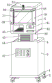
The invention discloses an ecological agriculture informatization service management platform which comprises a base, wherein pulleys are arranged at four corners of the bottom of the base, a fixed seat is arranged at the top of the base, a control cabinet is connected inside the fixed seat in a sliding manner, and a display panel is arranged at the top of the control cabinet. The adjusting mechanism and the fixing mechanism are matched with each other, so that the control cabinet is lifted in the fixing seat to meet the requirements of operators with different heights, the practicability is improved, meanwhile, the display panel is rotated, the control cabinet drives the placing plate to rotate, the sliding block is rotated in the guide rail, the display panel is rotated by 360 degrees, the use at different angles is facilitated, the bevel gear is rotated, the steering gear is rotated to drive the clamping plate hinged to the outer wall of the movable rod to clamp and fix an electrical component, the component is prevented from colliding during moving, and meanwhile, the component is convenient to overhaul and maintain.
Description
Technical Field
The invention relates to the technical field of agricultural information, in particular to an ecological agricultural informatization service management platform.
Background
The ecological agriculture is established according to ecological and economic principles by using modern scientific and technical achievements, modern management means and effective experience of traditional agriculture, and can obtain modern high-efficiency agriculture with higher economic, ecological and social benefits. With the development of scientific technology, information technology is more and more widely applied to the production process of ecological agriculture, particularly the application of internet of things technology in the agricultural field, so that people who carry out ecological agriculture production can obtain data such as temperature, humidity, illumination time, nutrient elements and trace elements required by crop growth in real time by using various terminals, and through comprehensive analysis of the data on a background, the optimal growth elements of different crops in different time periods can be obtained, so that feedback control is carried out, and finally an ideal growth environment is provided for the crops. The Internet of things acquires any object or process needing monitoring, connection and interaction in real time through technologies such as a sensor, a radio frequency identification technology, a global positioning system and the like, acquires various required information such as sound, light, heat, electricity, mechanics, chemistry, position and the like, realizes the ubiquitous connection of objects, objects and people through various possible network accesses, realizes intelligent sensing, identification and management of the objects and the process, is in a starting stage in the development of the Internet of things at present, and needs to provide an integrated agricultural Internet of things system supporting heterogeneous environment.
Among the prior art, because ecological agriculture information-based service management platform equipment structure is single, can't realize altitude mixture control, can't be according to the operating personnel of different heights, and can't carry out the angle modulation, for it provides comfortable, convenient operation service, equipment produces vibrations easily at the removal in-process simultaneously, and inside electrical components leads to damaging from breaking away from the bump easily, and the radiating effect can't guarantee.
Therefore, it is necessary to invent an ecological agriculture information-based service management platform to solve the above problems.
Disclosure of Invention
The invention aims to provide an ecological agriculture informatization service management platform, which fixes electrical elements in a control cabinet through the mutual matching of an adjusting mechanism and a fixing mechanism, and can adjust the height and the angle of the control cabinet up and down so as to overcome the defects in the technology.
In order to achieve the above purpose, the invention provides the following technical scheme: an ecological agriculture informatization service management platform comprises a base, pulleys are arranged at four corners of the bottom of the base, a fixed seat is arranged at the top of the base, a control cabinet is connected inside the fixed seat in a sliding manner, a display panel is arranged at the top of the control cabinet, and an adjusting mechanism is arranged at the bottom end of the inner wall of the fixed seat;
the adjusting mechanism comprises a double-drive motor, a supporting plate is arranged at the top of the double-drive motor, a screw rod is arranged at the output end of the double-drive motor, a lantern ring is movably sleeved on the outer wall of the screw rod, a moving rod is hinged to the top of the lantern ring, and the two moving rods are hinged to the bottom of the supporting plate;
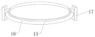
the top of the supporting plate is provided with a placing bin, the bottom end in the placing bin is provided with a placing plate, the cross section of the placing plate is circular, the outer wall of the placing plate is fixedly connected with a sliding block, the outer wall of the sliding block is connected with a guide rail in a sliding manner, the placing plate is rotatably connected with the guide rail through the sliding block, the number of the guide rails is two, the two guide rails are symmetrically arranged around the central axis of the placing bin, one side of the outer wall of the guide rail is fixedly connected with the placing bin, the control cabinet is positioned at the top of the placing plate, and a fixing component is arranged in the control cabinet;
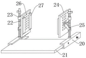
the fixed assembly comprises two groups of slide rails, the number of each group of slide rails is two, the two groups of slide rails are symmetrically arranged about the central axis of the inner wall of the control cabinet, the slide rails are fixedly connected with the control cabinet through bolts, a pull plate is connected between the two slide rails in a sliding manner, the central axis of the top of each slide rail is provided with a lead screw, a first bearing is arranged at the joint of the lead screw and the slide rails, moving rings are movably sleeved on the two sides of the outer wall of the lead screw, a moving rod is hinged to one side of the outer wall of each moving ring, clamping plates are arranged on the two sides of the top of each pull plate, and the two moving rods are hinged to the clamping plates;
the fan is arranged on each of two sides of the inner wall of the control cabinet, the filter screen is arranged on one side of the outer wall of the fan, the mounting plate is fixedly connected to one side of the outer wall of the filter screen, and the mounting plate is fixedly connected with the control cabinet through bolts.
Preferably, the two sides of the bottom end of the inner wall of the fixing seat are fixedly connected with movable cylinders, the inner wall of each movable cylinder is connected with a supporting rod in a sliding mode, the bottom of each supporting rod is fixedly connected with a cushioning spring, the top of each supporting rod is fixedly connected with a supporting plate, and a second bearing is arranged at the joint of each screw and each movable cylinder.
Preferably, the both sides of splint outer wall all fixedly connected with elastic plate, the louvre has been seted up to the splint inner wall, the quantity of louvre sets up to a plurality ofly.
Preferably, the top of the screw rod is fixedly connected with a steering gear, the outer wall of the steering gear is meshed with a bevel gear, one side of the inner wall of the bevel gear penetrates through the control cabinet and extends to one side of the outer wall, a third bearing is arranged at the joint of the bevel gear and the control cabinet, and a rotating handle is fixedly connected to one side of the outer wall of the bevel gear.
Preferably, the both sides of the outer wall of the display panel are provided with mounting boxes, the both sides of the inner wall of the mounting box (34) are provided with rotating rollers, the outer wall of each rotating roller is fixedly connected with gears, two gears are connected with chains in a transmission mode, and the chains are fixedly connected with cleaning wheels.
Preferably, the mounting box inner wall one side has been seted up the spout, the cleaning wheel runs through the spout, the live-rollers runs through the mounting box and extends to mounting box outer wall one side, live-rollers outer wall one side is equipped with the rotation handle.
Preferably, display panel inner wall one side is equipped with the display screen, display panel inner wall top is provided with the camera, the camera top is rotated and is connected with the protective cover, display panel bottom one side is provided with input panel, input panel outer wall one side is provided with the ID card and reads the ware, the ID card reads the ware bottom and is provided with the card reader.
Preferably, a box door is hinged to one side of the inner wall of the control cabinet, an air deflector is arranged on the inner wall of the box door, a heat dissipation plate is arranged on one side of the inside of the fixing seat, and a control panel is arranged on one side of the inner wall of the outer wall of the fixing seat.
In the technical scheme, the invention provides the following technical effects and advantages:
1. through the mutually supporting of adjustment mechanism and fixed establishment, make the control box go up and down inside the fixing base, with the demand that satisfies the operating personnel of different heights, the practicality has been increased, and simultaneously, rotate display panel, make the control box drive and place the board and rotate, thereby make the slider rotate inside the guide rail, thereby make display panel carry out 360 rotations, make things convenient for different angles to use, the flexibility of device has been improved, bevel gear rotates simultaneously, drive bevel gear outer wall meshed's steering gear rotates, make the removal hoop of lead screw outer wall both sides move to relative or the equidirectional removal, it presss from both sides tight fixedly to drive movable rod outer wall articulated splint to electrical components, when preventing components and parts from producing the collision in the removal, also be convenient for overhaul the maintenance to components and parts.
2. Through being provided with the fan at control machine incasement wall, be convenient for reduce the temperature of control machine case fast with the heat discharge of control machine incasement portion, guaranteed the normal operating of equipment, simultaneously to rotate the rotation handle, make the clean wheel of chain outer wall reciprocate, clean the display screen, keep the cleanness of operation display process, ensure to test the effect better.
Drawings
In order to more clearly illustrate the embodiments of the present application or technical solutions in the prior art, the drawings needed to be used in the embodiments will be briefly described below, and it is obvious that the drawings in the following description are only some embodiments described in the present invention, and other drawings can be obtained by those skilled in the art according to the drawings.
FIG. 1 is a schematic view of the overall structure of the present invention;
FIG. 2 is a cross-sectional view of the overall construction of the present invention;
FIG. 3 is a schematic view of the connection structure of the guide rail and the sliding block of the present invention;
FIG. 4 is a partial schematic view of the fixing assembly of the present invention;
FIG. 5 is a schematic view of a connection structure of a control cabinet and a fixing seat according to the present invention;
FIG. 6 is an enlarged view of the structure of FIG. 2A according to the present invention;
FIG. 7 is an enlarged view of the structure of FIG. 2B according to the present invention.
Description of reference numerals:
1. a base; 2. a pulley; 3. a fixed seat; 4. a control cabinet; 5. a display panel; 6. a movable barrel; 7. a support bar; 8. a support plate; 9. a cushioning spring; 10. a dual drive motor; 11. a screw; 12. a collar; 13. a travel bar; 14. placing a bin; 15. placing the plate; 16. a slider; 17. a guide rail; 18. a fan; 19. a filter screen; 20. a slide rail; 21. a drawing plate; 22. a screw rod; 23. a moving ring; 24. a splint; 25. a movable rod; 26. heat dissipation holes; 27. an elastic plate; 28. a steering gear; 29. a bevel gear; 30. rotating the handle; 31. a display screen; 32. a camera; 33. a protective cover; 34. mounting a box; 35. a rotating roller; 36. a gear; 37. a chain; 38. a chute; 39. a cleaning wheel; 40. an input panel; 41. an identity card reader; 42. a card reader; 43. a box door; 44. an air deflector; 45. a heat dissipation plate; 46. mounting a plate; 47. a control panel; 48. the handle is rotated.
Detailed Description
In order to make the technical solutions of the present invention better understood, those skilled in the art will now describe the present invention in further detail with reference to the accompanying drawings.
The invention provides an ecological agriculture informatization service management platform as shown in figures 1-7, which comprises a base 1, wherein pulleys 2 are arranged at four corners of the bottom of the base 1, a fixed seat 3 is arranged at the top of the base 1, a control cabinet 4 is connected in the fixed seat 3 in a sliding manner, a display panel 5 is arranged at the top of the control cabinet 4, and an adjusting mechanism is arranged at the bottom end of the inner wall of the fixed seat 3;
the adjusting mechanism comprises a double-drive motor 10, a supporting plate 8 is arranged at the top of the double-drive motor 10, a screw rod 11 is arranged at the output end of the double-drive motor 10, a sleeve ring 12 is movably sleeved on the outer wall of the screw rod 11, a moving rod 13 is hinged to the top of the sleeve ring 12, and the two moving rods 13 are hinged to the bottom of the supporting plate 8;
a placing bin 14 is arranged at the top of the supporting plate 8, a placing plate 15 is arranged at the bottom end inside the placing bin 14, the cross section of the placing plate 15 is circular, a sliding block 16 is fixedly connected to the outer wall of the placing plate 15, a guide rail 17 is slidably connected to the outer wall of the sliding block 16, the placing plate 15 is rotatably connected with the guide rail 17 through the sliding block 16, the number of the guide rails 17 is two, the two guide rails 17 are symmetrically arranged around the central axis of the placing bin 14, one side of the outer wall of the guide rail 17 is fixedly connected with the placing bin 14, the controller case 4 is positioned at the top of the placing plate 15, and a fixing component is arranged inside the controller case 4;
the fixed assembly comprises two sliding rails 20, the number of the sliding rails 20 is two, the number of each sliding rail 20 is two, the two sliding rails 20 are symmetrically arranged about the central axis of the inner wall of the control cabinet 4, the sliding rails 20 are fixedly connected with the control cabinet 4 through bolts, a drawing plate 21 is slidably connected between the two sliding rails 20, a lead screw 22 is arranged at the central axis of the top of each sliding rail 20, a first bearing is arranged at the joint of the lead screw 22 and the corresponding sliding rail 20, moving rings 23 are movably sleeved on two sides of the outer wall of each lead screw 22, moving rods 25 are hinged on one side of the outer wall of each moving ring 23, clamping plates 24 are arranged on two sides of the top of each drawing plate 21, and the two moving rods 25 are hinged with the clamping plates 24;
the fan 18 is arranged on each of two sides of the inner wall of the control cabinet 4, the filter screen 19 is arranged on one side of the outer wall of the fan 18, the mounting plate 46 is fixedly connected to one side of the outer wall of the filter screen 19, and the mounting plate 46 is fixedly connected with the control cabinet 4 through bolts.
Further, in the above technical scheme, the two sides of the bottom end of the inner wall of the fixing seat 3 are fixedly connected with a movable cylinder 6, the inner wall of the movable cylinder 6 is slidably connected with a support rod 7, the bottom of the support rod 7 is fixedly connected with a cushioning spring 9, the top of the support rod 7 is fixedly connected with a support plate 8, and a second bearing is arranged at the joint of the screw rod 11 and the movable cylinder 6.
Further, in the above technical scheme, the elastic plates 27 are fixedly connected to two sides of the outer wall of the clamping plate 24, the heat dissipation holes 26 are formed in the inner wall of the clamping plate 24, and the number of the heat dissipation holes 26 is multiple.
Further, in the above technical solution, a steering gear 28 is fixedly connected to the top of the screw rod 22, a bevel gear 29 is engaged with the outer wall of the steering gear 28, one side of the inner wall of the bevel gear 29 extends to one side of the outer wall by penetrating through the control cabinet 4, a third bearing is arranged at the connection position of the bevel gear 29 and the control cabinet 4, and a rotating handle 30 is fixedly connected to one side of the outer wall of the bevel gear 29.
Further, in the above technical scheme, mounting boxes 34 are arranged on two sides of the outer wall of the display panel 5, rotating rollers 35 are arranged on two sides of the inner wall of each mounting box 34, gears 36 are fixedly connected to the outer wall of each rotating roller 35, chains 37 are connected between the gears 36 in a transmission manner, and cleaning wheels 39 are fixedly connected between the chains 37.
Further, in the above technical solution, a sliding groove 38 is formed in one side of the inner wall of the mounting box 34, the cleaning wheel 39 penetrates through the sliding groove 38, the rotating roller 35 penetrates through the mounting box 34 and extends to one side of the outer wall of the mounting box 34, and a rotating handle 48 is arranged on one side of the outer wall of the rotating roller 35.
Further, in the above technical scheme, 5 inner wall one sides of display panel are equipped with display screen 31, 5 inner wall top of display panel is provided with camera 32, camera 32 top is rotated and is connected with protective cover 33, 5 bottom one side of display panel is provided with input panel 40, input panel 40 outer wall one side is provided with ID card reader 41, ID card reader 41 bottom is provided with card reader 42.
Further, in the above technical solution, a door 43 is hinged to one side of the inner wall of the control cabinet 4, an air deflector 44 is disposed on the inner wall of the door 43, a heat dissipation plate 45 is disposed on one side of the inside of the fixing base 3, and a control panel 47 is disposed on one side of the inner wall of the outer wall of the fixing base 3.
This practical theory of operation:
referring to the attached drawings 1-7 of the specification, when the invention is used, the screw rod 11 is driven to rotate by the rotation of the output shaft of the double-drive motor 10, so that the lantern ring 12 on the outer wall of the screw rod 11 moves, the two moving rods 13 are driven to move left and right, the supporting plate 8 is driven to move up and down, the control cabinet 4 is lifted up and down in the fixed seat 3 to meet the requirements of operators with different heights, the practicability is increased, the supporting rods 7 are fixedly connected to two sides of the bottom of the supporting plate 8, the damping springs 9 at the bottoms of the supporting rods 7 enable the control cabinet 4 to keep stable in the lifting and descending process and not to shake when the supporting rods rise to the highest point, meanwhile, the display panel 5 is rotated, the control cabinet 4 drives the placing plate 15 to rotate, the sliding block 16 rotates in the guide rail 17, the display panel 5 rotates by 360 degrees, and the use at different angles is convenient, the flexibility of the device is improved, in addition, a fixing component is arranged in the control cabinet 4, the door 43 is opened, then the electrical component is placed on the top of the drawing plate 21, then the rotating handle 30 is rotated to rotate the bevel gear 29, so as to drive the steering gear 28 meshed with the outer wall of the bevel gear 29 to rotate, the moving rings 23 on the two sides of the outer wall of the screw rod 22 move towards the opposite direction or the same direction, the clamping plates 24 hinged with the outer wall of the moving rod 25 are driven to clamp and fix the electrical component, the component is prevented from colliding during moving, and meanwhile, the component is convenient to overhaul and maintain,
referring to the attached drawings 1-7 of the specification, the fan 18 is arranged on the inner wall of the control cabinet 4, so that heat inside the control cabinet 4 can be conveniently discharged into the fixed seat 3, and then discharged through the heat dissipation plate 45, most of heat emitted by control components in the control cabinet 4 during working can be rapidly taken away, the temperature of the control cabinet 4 is rapidly reduced, and normal operation of equipment is ensured, meanwhile, the rotating handle 48 is rotated, so that the rotating roller 35 drives the gear 36 to rotate, the chain 37 meshed with the outer wall of the gear 36 is driven to move up and down, the cleaning wheel 39 on the outer wall of the chain 37 moves up and down, the display screen 31 is cleaned, the cleanness of an operation display process is kept, and a better experience effect is ensured.
While certain exemplary embodiments of the present invention have been described above by way of illustration only, it will be apparent to those of ordinary skill in the art that the described embodiments may be modified in various different ways without departing from the spirit and scope of the invention. Accordingly, the drawings and description are illustrative in nature and should not be construed as limiting the scope of the invention.
Claims (8)
1. The utility model provides an ecological agriculture information-based service management platform, includes base (1), its characterized in that: pulleys (2) are arranged at four corners of the bottom of the base (1), a fixed seat (3) is arranged at the top of the base (1), a control cabinet (4) is connected to the inside of the fixed seat (3) in a sliding manner, a display panel (5) is arranged at the top of the control cabinet (4), and an adjusting mechanism is arranged at the bottom end of the inner wall of the fixed seat (3);
the adjusting mechanism comprises a double-drive motor (10), a supporting plate (8) is arranged at the top of the double-drive motor (10), a screw (11) is arranged at the output end of the double-drive motor (10), a sleeve ring (12) is movably sleeved on the outer wall of the screw (11), a moving rod (13) is hinged to the top of the sleeve ring (12), and the two moving rods (13) are hinged to the bottom of the supporting plate (8);
the top of the supporting plate (8) is provided with a placing bin (14), the bottom inside the placing bin (14) is provided with a placing plate (15), the cross section of the placing plate (15) is circular, the outer wall of the placing plate (15) is fixedly connected with a sliding block (16), the outer wall of the sliding block (16) is slidably connected with a guide rail (17), the placing plate (15) is rotatably connected with the guide rail (17) through the sliding block (16), the number of the guide rails (17) is two, the two guide rails (17) are symmetrically arranged at the central axis of the placing bin (14), one side of the outer wall of each guide rail (17) is fixedly connected with the placing bin (14), the control cabinet (4) is positioned at the top of the placing plate (15), and a fixing component is arranged inside the control cabinet (4);
the fixed assembly comprises two groups of slide rails (20), the number of the slide rails (20) is two, the number of the slide rails (20) in each group is two, the two groups of slide rails (20) are symmetrically arranged around the central axis of the inner wall of the control cabinet (4), the slide rails (20) are fixedly connected with the control cabinet (4) through bolts, a drawing plate (21) is connected between the two slide rails (20) in a sliding way, the central axis of the top of the slide rail (20) is provided with a screw rod (22), the joint of the screw rod (22) and the slide rail (20) is provided with a first bearing, the two sides of the outer wall of the screw rod (22) are movably sleeved with moving rings (23), one side of the outer wall of each moving ring (23) is hinged with a moving rod (25), clamping plates (24) are arranged on two sides of the top of the drawing plate (21), and the two movable rods (25) are hinged with the clamping plates (24);
control machine case (4) inner wall both sides all are equipped with fan (18), fan (18) outer wall one side is equipped with filter screen (19), filter screen (19) outer wall one side fixedly connected with mounting panel (46), mounting panel (46) pass through bolt and control machine case (4) fixed connection.
2. The ecological agriculture informatization service management platform according to claim 1, characterized in that: the utility model discloses a damping device for a bicycle, including fixing base (3), a movable section of thick bamboo (6) of equal fixedly connected with in fixing base (3) inner wall bottom both sides, movable section of thick bamboo (6) inner wall sliding connection has bracing piece (7), bracing piece (7) bottom fixedly connected with bradyseism spring (9), two bracing piece (7) top and backup pad (8) fixed connection, screw rod (11) and a movable section of thick bamboo (6) junction are equipped with the second bearing.
3. The ecological agriculture informatization service management platform according to claim 1, characterized in that: the utility model discloses a splint, including splint (24), heat dissipation hole (26) are set up to a plurality of, splint (24) outer wall both sides equal fixedly connected with elastic plate (27), splint (24) inner wall has seted up louvre (26).
4. The ecological agriculture informatization service management platform according to claim 1, characterized in that: the top of the screw rod (22) is fixedly connected with a steering gear (28), the outer wall of the steering gear (28) is meshed with a bevel gear (29), one side of the inner wall of the bevel gear (29) penetrates through the control cabinet (4) and extends to one side of the outer wall, a third bearing is arranged at the joint of the bevel gear (29) and the control cabinet (4), and a rotating handle (30) is fixedly connected to one side of the outer wall of the bevel gear (29).
5. The ecological agriculture informatization service management platform according to claim 1, characterized in that: display panel (5) outer wall both sides all are equipped with mounting box (34), mounting box (34) inner wall both sides all are equipped with live-rollers (35), live-rollers (35) outer wall fixedly connected with gear (36), two the transmission is connected with chain (37), two between gear (36) fixedly connected with cleaning wheel (39) between chain (37).
6. The ecological agriculture informatization service management platform according to claim 5, characterized in that: spout (38) have been seted up to mounting box (34) inner wall one side, clean wheel (39) run through spout (38), live-rollers (35) run through mounting box (34) and extend to mounting box (34) outer wall one side, live-rollers (35) outer wall one side is equipped with rotation handle (48).
7. The ecological agriculture informatization service management platform according to claim 1, characterized in that: display panel (5) inner wall one side is equipped with display screen (31), display panel (5) inner wall top is provided with camera (32), camera (32) top is rotated and is connected with protective cover (33), display panel (5) bottom one side is provided with input panel (40), input panel (40) outer wall one side is provided with ID card reader (41), ID card reader (41) bottom is provided with card reader (42).
8. The ecological agriculture informatization service management platform according to claim 1, characterized in that: a box door (43) is hinged to one side of the inner wall of the control cabinet (4), an air deflector (44) is arranged on the inner wall of the box door (43), a heat dissipation plate (45) is arranged on one side of the inside of the fixing seat (3), and a control panel (47) is arranged on one side of the inner wall of the outer wall of the fixing seat (3).
Priority Applications (1)
| Application Number | Priority Date | Filing Date | Title |
|---|---|---|---|
| CN202110617220.9A CN113238618A (en) | 2021-06-03 | 2021-06-03 | Ecological agriculture informatization service management platform |
Applications Claiming Priority (1)
| Application Number | Priority Date | Filing Date | Title |
|---|---|---|---|
| CN202110617220.9A CN113238618A (en) | 2021-06-03 | 2021-06-03 | Ecological agriculture informatization service management platform |
Publications (1)
| Publication Number | Publication Date |
|---|---|
| CN113238618A true CN113238618A (en) | 2021-08-10 |
Family
ID=77136434
Family Applications (1)
| Application Number | Title | Priority Date | Filing Date |
|---|---|---|---|
| CN202110617220.9A Pending CN113238618A (en) | 2021-06-03 | 2021-06-03 | Ecological agriculture informatization service management platform |
Country Status (1)
| Country | Link |
|---|---|
| CN (1) | CN113238618A (en) |
Cited By (1)
| Publication number | Priority date | Publication date | Assignee | Title |
|---|---|---|---|---|
| CN115171292A (en) * | 2022-06-28 | 2022-10-11 | 江苏振邦医用智能装备有限公司 | Self-service equipment for logistics service system |
Citations (9)
| Publication number | Priority date | Publication date | Assignee | Title |
|---|---|---|---|---|
| CN206875069U (en) * | 2017-07-01 | 2018-01-12 | 四川农业大学 | A kind of multi-party bit machine swivel mount |
| CN208027668U (en) * | 2018-01-31 | 2018-10-30 | 曾涛 | A kind of outdoor LED display screen with waterproof cover |
| CN109104845A (en) * | 2018-08-16 | 2018-12-28 | 安徽超清科技股份有限公司 | A kind of floating population's access management platform controller |
| CN209289098U (en) * | 2018-12-21 | 2019-08-23 | 浙江赛赛轴承有限公司 | A kind of fixture for processing vertical bearing seat |
| CN211165345U (en) * | 2019-08-27 | 2020-08-04 | 华创智造(天津)科技有限公司 | Base with buffering effect 3D printer |
| CN211219769U (en) * | 2019-07-09 | 2020-08-11 | 晋中职业技术学院 | Novel anchor clamps for machine-building |
| CN211694152U (en) * | 2020-02-04 | 2020-10-16 | 广州市新成长教育科技有限公司 | Human resource social security service all-in-one machine |
| CN211829080U (en) * | 2020-02-13 | 2020-10-30 | 李敏 | Fixing device for lithium battery machining |
| CN112201151A (en) * | 2020-10-09 | 2021-01-08 | 元保科创(北京)科技有限公司 | Insurance business-oriented insurance application and claim settlement service display platform |
-
2021
- 2021-06-03 CN CN202110617220.9A patent/CN113238618A/en active Pending
Patent Citations (9)
| Publication number | Priority date | Publication date | Assignee | Title |
|---|---|---|---|---|
| CN206875069U (en) * | 2017-07-01 | 2018-01-12 | 四川农业大学 | A kind of multi-party bit machine swivel mount |
| CN208027668U (en) * | 2018-01-31 | 2018-10-30 | 曾涛 | A kind of outdoor LED display screen with waterproof cover |
| CN109104845A (en) * | 2018-08-16 | 2018-12-28 | 安徽超清科技股份有限公司 | A kind of floating population's access management platform controller |
| CN209289098U (en) * | 2018-12-21 | 2019-08-23 | 浙江赛赛轴承有限公司 | A kind of fixture for processing vertical bearing seat |
| CN211219769U (en) * | 2019-07-09 | 2020-08-11 | 晋中职业技术学院 | Novel anchor clamps for machine-building |
| CN211165345U (en) * | 2019-08-27 | 2020-08-04 | 华创智造(天津)科技有限公司 | Base with buffering effect 3D printer |
| CN211694152U (en) * | 2020-02-04 | 2020-10-16 | 广州市新成长教育科技有限公司 | Human resource social security service all-in-one machine |
| CN211829080U (en) * | 2020-02-13 | 2020-10-30 | 李敏 | Fixing device for lithium battery machining |
| CN112201151A (en) * | 2020-10-09 | 2021-01-08 | 元保科创(北京)科技有限公司 | Insurance business-oriented insurance application and claim settlement service display platform |
Cited By (1)
| Publication number | Priority date | Publication date | Assignee | Title |
|---|---|---|---|---|
| CN115171292A (en) * | 2022-06-28 | 2022-10-11 | 江苏振邦医用智能装备有限公司 | Self-service equipment for logistics service system |
Similar Documents
| Publication | Publication Date | Title |
|---|---|---|
| CN113238618A (en) | Ecological agriculture informatization service management platform | |
| CN104521438A (en) | Shearing type shiny-leaved yellowhorn picking machine | |
| CN106584257A (en) | Plane polishing equipment | |
| CN108393630A (en) | A kind of steel reinforcement cage welding equipment | |
| CN105058394A (en) | Grabbing and arranging device for deburring | |
| CN109121721B (en) | Vibrating fruit picking device and picking method | |
| CN205471265U (en) | Automatic production device | |
| CN206826284U (en) | A kind of fixed-focus system of portable laser engraving machine | |
| CN109435468A (en) | A kind of spray head mobile device of draw-bar box type spray drawing machine | |
| CN206472378U (en) | One kind spray tin cream and patch combination equipment | |
| CN206084712U (en) | Plane polishing equipment | |
| CN205616187U (en) | Turning device of full -automatic application equipment | |
| CN209051918U (en) | Sorter | |
| CN111003043A (en) | Raw material transportation system based on 5G network and used for intelligent factory | |
| CN208305034U (en) | Bearing line grabbing device | |
| CN215929041U (en) | Agricultural product quality safety monitoring system based on Internet of things | |
| CN214037451U (en) | Wisdom garden infrared camera monitoring device | |
| CN214526723U (en) | But control type circulation transfer chain | |
| CN108527134A (en) | A kind of burnishing device for furniture processing | |
| CN212168236U (en) | Conveying equipment is used in touch-sensitive screen production | |
| CN209039844U (en) | A kind of non-woven fabrics guillotine pan feeding transmission device | |
| CN206358904U (en) | A kind of foamed products cutting agency with water cooling | |
| CN101628276A (en) | Tray circular carrying mechanism and carrying method | |
| CN109704058A (en) | A kind of stabilization, reliable pallet hold and migrate equipment and its working method | |
| CN219520936U (en) | Intelligent welding parameter control device |
Legal Events
| Date | Code | Title | Description |
|---|---|---|---|
| PB01 | Publication | ||
| PB01 | Publication | ||
| SE01 | Entry into force of request for substantive examination | ||
| SE01 | Entry into force of request for substantive examination |