CN113236451A - Device for heating fuel oil by utilizing exhaust pipe waste gas - Google Patents
Device for heating fuel oil by utilizing exhaust pipe waste gas Download PDFInfo
- Publication number
- CN113236451A CN113236451A CN202110586965.3A CN202110586965A CN113236451A CN 113236451 A CN113236451 A CN 113236451A CN 202110586965 A CN202110586965 A CN 202110586965A CN 113236451 A CN113236451 A CN 113236451A
- Authority
- CN
- China
- Prior art keywords
- heat exchange
- exhaust pipe
- exchange device
- heat
- heating fuel
- Prior art date
- Legal status (The legal status is an assumption and is not a legal conclusion. Google has not performed a legal analysis and makes no representation as to the accuracy of the status listed.)
- Pending
Links
Images
Classifications
-
- F—MECHANICAL ENGINEERING; LIGHTING; HEATING; WEAPONS; BLASTING
- F02—COMBUSTION ENGINES; HOT-GAS OR COMBUSTION-PRODUCT ENGINE PLANTS
- F02M—SUPPLYING COMBUSTION ENGINES IN GENERAL WITH COMBUSTIBLE MIXTURES OR CONSTITUENTS THEREOF
- F02M31/00—Apparatus for thermally treating combustion-air, fuel, or fuel-air mixture
- F02M31/02—Apparatus for thermally treating combustion-air, fuel, or fuel-air mixture for heating
- F02M31/16—Other apparatus for heating fuel
-
- F—MECHANICAL ENGINEERING; LIGHTING; HEATING; WEAPONS; BLASTING
- F02—COMBUSTION ENGINES; HOT-GAS OR COMBUSTION-PRODUCT ENGINE PLANTS
- F02G—HOT GAS OR COMBUSTION-PRODUCT POSITIVE-DISPLACEMENT ENGINE PLANTS; USE OF WASTE HEAT OF COMBUSTION ENGINES; NOT OTHERWISE PROVIDED FOR
- F02G5/00—Profiting from waste heat of combustion engines, not otherwise provided for
- F02G5/02—Profiting from waste heat of exhaust gases
-
- Y—GENERAL TAGGING OF NEW TECHNOLOGICAL DEVELOPMENTS; GENERAL TAGGING OF CROSS-SECTIONAL TECHNOLOGIES SPANNING OVER SEVERAL SECTIONS OF THE IPC; TECHNICAL SUBJECTS COVERED BY FORMER USPC CROSS-REFERENCE ART COLLECTIONS [XRACs] AND DIGESTS
- Y02—TECHNOLOGIES OR APPLICATIONS FOR MITIGATION OR ADAPTATION AGAINST CLIMATE CHANGE
- Y02T—CLIMATE CHANGE MITIGATION TECHNOLOGIES RELATED TO TRANSPORTATION
- Y02T10/00—Road transport of goods or passengers
- Y02T10/10—Internal combustion engine [ICE] based vehicles
- Y02T10/12—Improving ICE efficiencies
Landscapes
- Engineering & Computer Science (AREA)
- Chemical & Material Sciences (AREA)
- Combustion & Propulsion (AREA)
- Mechanical Engineering (AREA)
- General Engineering & Computer Science (AREA)
- Exhaust Gas After Treatment (AREA)
Abstract
The invention discloses a device for heating fuel oil by utilizing exhaust pipe waste gas, which is characterized by comprising a first heat exchange device, a second heat exchange device, a driving pump, a pipeline and a heat exchange medium, wherein the first heat exchange device, the second heat exchange device and the driving pump are connected through the pipeline to form a closed system, and the heat exchange medium is arranged in the closed system; the first heat exchange device is arranged outside an exhaust pipe of the engine; the second heat exchange device is arranged outside a fuel oil pipe of the engine. According to the technical scheme provided by the invention, the waste heat of the waste gas is recovered by using the explosion-proof heating oil, the waste heat is recovered as far as possible to heat the fuel oil on the premise of not influencing post-treatment such as three-way catalysis, and a combustion system is further optimized while the current highest energy-saving and emission-reducing technology is met. The system is safe and reliable, energy-saving and environment-friendly, and can greatly recover and effectively utilize waste heat.
Description
Technical Field
The invention relates to the technical field of automobile fuel heating, in particular to a device for heating fuel by utilizing exhaust pipe waste gas.
Background
In the design process of the core combustion system of the engine, fuel atomization is a core technology for realizing clean and efficient combustion, and how to realize efficient fuel atomization so as to better mix fuel and air into homogeneous gas is the key of energy conservation and emission reduction of the combustion system. At present, the main technical means for fuel atomization is high-pressure injection, namely, the fuel rail pressure is increased, and the fuel and the pressure difference of backpressure are utilized to carry out crushing atomization.
Research shows that the fuel temperature is properly increased, the fuel flashing spraying is realized, the fuel atomization and evaporation effects can be obviously improved under the condition of lower fuel injection pressure, and the effects of reducing the tail gas emission of the gasoline engine and improving the fuel economy are achieved.
The method for heating fuel oil and realizing flash-boiling spraying of the current mainstream is to directly heat the fuel oil by using an electric heating mode, such as solving the problems of cold start and the like by using cooling water to rapidly heat up in a thermal management system, rapidly warm up and heating the fuel oil by using an electric heating oil sprayer design.
A large amount of heat energy is stored in tail gas of the engine, energy consumption of about 1/3 of a traditional engine is discharged from waste gas, and resource waste is caused because the energy cannot be recovered. The fuel temperature required by the complete flash-boiling spraying is about 200-300 ℃, and the temperature of the tail gas can reach 900 ℃, so that the extreme fuel heating condition and requirement can be completely met.
Current electric heating's mode electrical system is comparatively complicated, generally integrates on the cylinder body, arranges the difficulty. In addition, the energy consumption of an electric heating mode is more, and the heat efficiency of the whole machine is reduced. In addition, electric heating has the dangers of electric leakage, reduced reliability, fuel overheating explosion and the like.
Therefore, those skilled in the art have been devoted to developing a device for heating fuel using exhaust gas of an exhaust pipe to solve the above-mentioned problems of the electric heating system.
Disclosure of Invention
In view of the above-mentioned drawbacks of the prior art, the present invention is directed to a fuel heating system using exhaust gas from an engine exhaust pipe to avoid many drawbacks of the electric heating system.
In order to achieve the purpose, the invention provides a device for heating fuel oil by using exhaust pipe waste gas, which is characterized by comprising a first heat exchange device, a second heat exchange device, a driving pump, a pipeline and a heat exchange medium, wherein the first heat exchange device, the second heat exchange device and the driving pump are connected through the pipeline to form a closed system, and the heat exchange medium is arranged in the closed system; the first heat exchange device is arranged outside an exhaust pipe of the engine; the second heat exchange device is arranged outside a fuel oil pipe of the engine.
Further, the second heat exchange device is arranged at the rear end of the high-pressure oil pump and the front end of the oil injector.
Furthermore, the first heat exchange device is made of metal.
Furthermore, the first heat exchange device is made of a high-temperature-resistant non-metallic material.
Furthermore, the second heat exchange device is made of metal.
Furthermore, the second heat exchange device is made of a high-temperature-resistant non-metallic material.
Furthermore, the pipeline is made of metal.
Furthermore, the pipeline is made of high-temperature-resistant non-metallic materials.
Further, the heat exchange medium is a liquid having fluidity.
Further, the liquid is oil.
The invention has the beneficial effects that:
the invention provides a device for heating fuel oil by utilizing exhaust pipe waste gas, which utilizes heat conduction oil to recover waste heat of an exhaust pipe, and the specific recovery mode is as follows: and selecting an exhaust position, avoiding the tail gas post-treatment device, heating heat conduction oil, and transferring heat to the front end of the oil rail by utilizing the heat conduction oil. The heat exchange tube is arranged at the front end of the oil rail, and heat conduction oil is used for exchanging heat of the oil tube to heat fuel oil. The heat conducting oil is circularly returned to the heat conducting oil pump and circularly reciprocates.
According to the technical scheme provided by the invention, the waste heat of the waste gas is recovered by using the explosion-proof heating oil, the waste heat is recovered as far as possible to heat the fuel oil on the premise of not influencing post-treatment such as three-way catalysis, and a combustion system is further optimized while the current highest energy-saving and emission-reducing technology is met. The system is safe and reliable, energy-saving and environment-friendly, and can greatly recover and effectively utilize waste heat.
The conception, the specific structure and the technical effects of the present invention will be further described with reference to the accompanying drawings to fully understand the objects, the features and the effects of the present invention.
Drawings
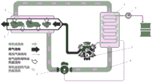
Fig. 1 is a schematic overall structure diagram of a preferred embodiment of the present invention.
The system comprises an exhaust pipe 1, a first heat exchange device 2, a second heat exchange device 3, a high-pressure oil rail 4, a four-cylinder engine 5, a pipeline 6 and a driving pump 7.
Detailed Description
The technical contents of the preferred embodiments of the present invention will be more clearly and easily understood by referring to the drawings attached to the specification. The present invention may be embodied in many different forms of embodiments and the scope of the invention is not limited to the embodiments set forth herein.
In the drawings, structurally identical elements are represented by like reference numerals, and structurally or functionally similar elements are represented by like reference numerals throughout the several views. The size and thickness of each component shown in the drawings are arbitrarily illustrated, and the present invention is not limited to the size and thickness of each component. The thickness of the components may be exaggerated where appropriate in the figures to improve clarity.
Fig. 1 shows a schematic diagram of the overall structure of a device for heating fuel by using exhaust gas of an exhaust pipe. The first heat exchange device 2, the second heat exchange device 3 and the driving pump 7 are connected through a pipeline 6 to form a closed system, the heat exchange medium of the embodiment is heat conduction oil, and the heat conduction oil is arranged in the closed system. The first heat exchange device 2 is arranged outside the engine exhaust pipe 1; the second heat exchange means 3 is arranged externally of the engine fuel line. The drive pump 7 drives the heat conduction oil, the heat conduction oil carries out heat exchange treatment on the part of the exhaust pipe 1, the temperature is increased, and the high-temperature heat conduction oil carries out heat exchange at the fuel oil pipe of the engine to heat fuel oil.
The foregoing detailed description of the preferred embodiments of the invention has been presented. It should be understood that numerous modifications and variations could be devised by those skilled in the art in light of the present teachings without departing from the inventive concepts. Therefore, the technical solutions available to those skilled in the art through logic analysis, reasoning and limited experiments based on the prior art according to the concept of the present invention should be within the scope of protection defined by the claims.
Claims (10)
1. A device for heating fuel oil by using exhaust pipe waste gas is characterized by comprising a first heat exchange device, a second heat exchange device, a driving pump, a pipeline and a heat exchange medium, wherein the first heat exchange device, the second heat exchange device and the driving pump are connected through the pipeline to form a closed system, and the heat exchange medium is arranged in the closed system; the first heat exchange device is arranged outside an exhaust pipe of the engine; the second heat exchange device is arranged outside a fuel oil pipe of the engine.
2. The apparatus for heating fuel using exhaust pipe exhaust gas according to claim 1, wherein the second heat exchanging means is disposed at a rear end of the high-pressure oil pump and a front end of the injector.
3. The apparatus for heating fuel using exhaust pipe exhaust gas according to claim 1, wherein the first heat exchanging means is made of metal.
4. The device for heating fuel oil by using exhaust pipe exhaust gas as claimed in claim 1, wherein the first heat exchanging means is made of a high temperature resistant non-metallic material.
5. The apparatus for heating fuel using exhaust pipe exhaust gas according to claim 1, wherein the second heat exchanging means is made of metal.
6. The apparatus for heating fuel using exhaust pipe exhaust gas according to claim 1, wherein the second heat exchanging means is made of a high temperature resistant non-metallic material.
7. The apparatus for heating fuel using exhaust pipe exhaust gas according to claim 1, wherein the pipe is made of metal.
8. The apparatus for heating fuel using exhaust pipe exhaust gas according to claim 1, wherein the pipe is made of a high temperature-resistant non-metallic material.
9. The apparatus for heating fuel using exhaust pipe exhaust gas according to claim 1, wherein the heat exchange medium is a liquid having fluidity.
10. The apparatus for heating fuel using exhaust pipe exhaust gas according to claim 9, wherein the liquid is oil.
Priority Applications (1)
| Application Number | Priority Date | Filing Date | Title |
|---|---|---|---|
| CN202110586965.3A CN113236451A (en) | 2021-05-27 | 2021-05-27 | Device for heating fuel oil by utilizing exhaust pipe waste gas |
Applications Claiming Priority (1)
| Application Number | Priority Date | Filing Date | Title |
|---|---|---|---|
| CN202110586965.3A CN113236451A (en) | 2021-05-27 | 2021-05-27 | Device for heating fuel oil by utilizing exhaust pipe waste gas |
Publications (1)
| Publication Number | Publication Date |
|---|---|
| CN113236451A true CN113236451A (en) | 2021-08-10 |
Family
ID=77139214
Family Applications (1)
| Application Number | Title | Priority Date | Filing Date |
|---|---|---|---|
| CN202110586965.3A Pending CN113236451A (en) | 2021-05-27 | 2021-05-27 | Device for heating fuel oil by utilizing exhaust pipe waste gas |
Country Status (1)
| Country | Link |
|---|---|
| CN (1) | CN113236451A (en) |
Citations (5)
| Publication number | Priority date | Publication date | Assignee | Title |
|---|---|---|---|---|
| DE19641700C1 (en) * | 1996-10-10 | 1997-10-30 | Daimler Benz Ag | Multiple heat-exchanger used in internal combustion engine |
| JP2009243278A (en) * | 2008-03-28 | 2009-10-22 | Hitachi Ltd | Engine system |
| CN103334819A (en) * | 2013-06-21 | 2013-10-02 | 高志男 | Residual heat recycling device for tail gas of automobile |
| CN206972401U (en) * | 2017-07-18 | 2018-02-06 | 辽宁工业大学 | A kind of automobile exhaust residual-heat used type oil tank heating apparatus |
| CN108049988A (en) * | 2017-09-07 | 2018-05-18 | 同济大学 | A kind of gasoline engine structure of Waste Heat Recovery high temperature grease mixing jetting |
-
2021
- 2021-05-27 CN CN202110586965.3A patent/CN113236451A/en active Pending
Patent Citations (5)
| Publication number | Priority date | Publication date | Assignee | Title |
|---|---|---|---|---|
| DE19641700C1 (en) * | 1996-10-10 | 1997-10-30 | Daimler Benz Ag | Multiple heat-exchanger used in internal combustion engine |
| JP2009243278A (en) * | 2008-03-28 | 2009-10-22 | Hitachi Ltd | Engine system |
| CN103334819A (en) * | 2013-06-21 | 2013-10-02 | 高志男 | Residual heat recycling device for tail gas of automobile |
| CN206972401U (en) * | 2017-07-18 | 2018-02-06 | 辽宁工业大学 | A kind of automobile exhaust residual-heat used type oil tank heating apparatus |
| CN108049988A (en) * | 2017-09-07 | 2018-05-18 | 同济大学 | A kind of gasoline engine structure of Waste Heat Recovery high temperature grease mixing jetting |
Non-Patent Citations (1)
| Title |
|---|
| 汪洋: "《引领未来的新能源》", 30 September 2014, 兰州:甘肃科学技术出版社 * |
Similar Documents
| Publication | Publication Date | Title |
|---|---|---|
| CN106677926B (en) | A kind of Structure of Internal-Combustion Engine of cylinder injection superheated water | |
| CN102758706B (en) | Engine oil tank heating device | |
| US20200300147A1 (en) | Internal combustion engine waste heat utilization system | |
| CN108049993A (en) | High temperature water supply system in a kind of reciprocating-piston Cylinder of Natural Gas Engine | |
| CN113236451A (en) | Device for heating fuel oil by utilizing exhaust pipe waste gas | |
| CN108952997B (en) | Engine waste heat utilization system based on bionic vapor chamber and pulsating heat pipe technology | |
| CN108049988A (en) | A kind of gasoline engine structure of Waste Heat Recovery high temperature grease mixing jetting | |
| CN204359181U (en) | Utilize the phase transition heat accumulation unit of engine exhaust waste heat | |
| CN100427733C (en) | Internal combustion engine exhaust heat energy recovery device | |
| CN221002981U (en) | Combined heat and power preheating system for cold region of engineering vehicle based on steam power cycle | |
| CN102927380A (en) | Water-oil composite tube and vehicle oil way anti-freezing device and method using same | |
| CN105626254A (en) | Chemical heat regeneration type diesel engine | |
| CN206360760U (en) | A kind of high efficiency automobile tail gas utilizing device | |
| CN104500192B (en) | Turbo-charged diesel intelligent high-efficiency purification method and device | |
| CN213510978U (en) | Diesel oil supply system | |
| CN208010504U (en) | Reduce the quick warming-up apparatus of gasoline engine cold start emission | |
| CN204113407U (en) | A kind of vehicle exhaust steamturbine conversion system | |
| CN202545065U (en) | Energy-saving emission-reduction device for diesel engine | |
| KR20100024622A (en) | Fuel preheating apparatus | |
| CN217002017U (en) | Engine waste heat utilization equipment who can be used to water tank | |
| CN116044635B (en) | Internal combustion engine energy saving and environmental protection control device and energy saving antifreeze | |
| CN221256990U (en) | Low-temperature cold starting device of diesel generating set | |
| CN204419318U (en) | I. C. engine exhaust thermal energy recovering device | |
| CN203769899U (en) | Automobile engine waste heat utilization system | |
| CN201599108U (en) | fuel steam engine |
Legal Events
| Date | Code | Title | Description |
|---|---|---|---|
| PB01 | Publication | ||
| PB01 | Publication | ||
| SE01 | Entry into force of request for substantive examination | ||
| SE01 | Entry into force of request for substantive examination |