Tunnel construction geological detection equipment based on BIM + GIS
Technical Field
The invention relates to the technical field of informatization and intellectualization of tunnel construction engineering management, in particular to tunnel construction geological detection equipment based on BIM + GIS.
Background
Along with the rapid development of national economy, the road traffic construction of China is vigorously developed in recent years, the construction scale of highways is continuously enlarged, the construction scale and the number of tunnels are greatly developed, the prior tunnel advanced prediction informatization management platform is a certain research on applying the GIS technology to the fields of geological engineering and geotechnical engineering at home and abroad, some software systems are presented, the software systems can realize three-dimensional simulation of surface topography and landform, have a stratum analysis function, have good application on a geometric modeling function, an analysis function and an interaction function, and when tunnel construction geological detection is carried out, detection is carried out on geology in a tunnel, then data is transmitted to a BIM three-dimensional model simulation device and a GIS geographic information platform, and analysis processing is carried out to obtain a three-dimensional visual graph and generate an automatic report of advanced geological prediction.
However, most of the existing tunnel construction geological detection is that a geological detection instrument is manually held to detect soil layers on the surface of a tunnel, the tunnel is in danger of collapse, great threat can be caused to personal safety, and the geological detector cannot accurately measure data of deep soil on the surface of the soil, so that the measurement error is large.
Disclosure of Invention
The invention aims to provide tunnel construction geological detection equipment based on BIM + GIS, so as to solve the problems in the background technology.
In order to achieve the purpose, the invention provides the following technical scheme: a tunnel construction geological detection device based on BIM + GIS comprises a shell, wherein a first through groove is formed in the upper surface of the inner wall of the lower side of the shell in a penetrating mode, a storage battery and a first supporting seat are fixedly connected to the upper surface of the inner wall of the lower side of the shell, the first supporting seat is located on the left side of the storage battery, a first motor is fixedly connected to the upper surface of the first supporting seat, a first rotating wheel is fixedly connected to the rear side of a rotating shaft of the first motor, a driving belt is rotatably connected to the side surface of the circumference of the first rotating wheel, a second rotating wheel is rotatably connected to the lower end of the inner wall of the driving belt, the lower end of the driving belt is located in the first through groove, a first connecting shaft is fixedly connected to the center of the front side and the rear side surface of the second rotating wheel in a penetrating mode, a third rotating wheel is fixedly connected to the front side surface and the rear side surface of the first connecting shaft, a track is rotatably connected to the side surface of the circumference of the third wheel, a track is rotatably connected to the right side surface of the inner wall of the track, the center of the opposite side surfaces of the four rotating wheels is fixedly connected with a connecting shaft II, four corners of the lower surface of the shell are fixedly connected with a first supporting rod I, the circumferential side surfaces of the connecting shaft I and the connecting shaft II penetrate through the lower ends of the front side surface and the rear side surface of the connecting supporting rod I in a rotating manner, the left side of the shell is provided with a drill bit II and a first protective cover, the center of the right side surface of the drill bit II is fixedly connected with a connecting shaft III, the center of the right side surface of the connecting shaft III is fixedly connected with a round rod II, the upper surface and the lower surface of the round rod II are fixedly connected with a slide rod II, the right end surfaces of the round rod II and the slide rod II are connected with a connecting pipe II in a sliding manner, the right side surface of the connecting pipe II is provided with a motor III, the right side surface of the connecting pipe II is fixedly connected with the left side surface of a rotating shaft of the motor III, the left side surface of the protective cover I is fixedly connected with the circumferential edge of the right side surface of the drill bit II, and the right end of the inner wall of the protective cover I is rotatably connected with a protective cover II, a second through groove is arranged at the lower end of the inner wall of the second protective cover in a penetrating way, a support plate is arranged above the second through groove, four corners of the lower surface of the first protective cover are fixedly connected with a second supporting rod, the lower surface of the second supporting rod is fixedly connected with the inner wall of the second protective cover, a geological detector is fixedly connected at the center of the lower surface of the supporting plate, the lower end of the geological detector is positioned in the second through groove, the left sides of the upper surface and the lower surface of the motor III are fixedly connected, the side surface of one end far away from the motor III is fixedly connected with the edge of the right end of the inner wall of the protective cover II, the lower surface of the motor III is fixedly connected with a supporting seat II, the lower surface of the supporting seat II is fixedly connected with a fixed transverse plate I, the left side lower extreme of the right flank fixed connection shell of fixed diaphragm one, the side all is provided with the threaded rod around the shell, the right side of shell is provided with BIM + GIS three-dimensional model simulation device.
Preferably, a second motor is fixedly connected to the center of the upper surface of the housing, a first support shaft is fixedly connected to the upper surface of a rotating shaft of the second motor, a first round rod is fixedly connected to the center of the upper surface of the first support shaft, a first slide rod is fixedly connected to the side surface of the circumference of the first round rod, a first connecting pipe is slidably connected to the upper ends of the surfaces of the first round rod and the first slide rod, a first round plate is fixedly connected to the upper surface of the first connecting pipe, a first gear is fixedly connected to the upper surface of the first round plate, a second round plate is fixedly connected to the upper surface of the first gear, a second gear is meshed with the front left side, the rear left side, the front right side and the rear right side of the first gear, a first threaded rod is fixedly connected to the upper surface of the lower surface of the second gear, a first drill bit is fixedly connected to the lower surface of the threaded rod, support columns are fixedly connected to the four corners of the upper surface of the housing, and transverse support columns are fixedly connected to the upper surface of the support columns, the utility model discloses a shovel native arc board, including the threaded surface of threaded rod, the threaded surface of threaded rod runs through the upper surface that threaded connection supported the diaphragm, the threaded surface lower extreme of threaded rod runs through fixedly connected with reinforcing ring, the lower surface circumference edge fixedly connected with shovel native arc board of reinforcing ring, the lower surface of shovel native arc board is the inclined plane, the left surface of shovel native arc board is seted up flutedly, shovel native arc board is the annular setting in reinforcing ring below.
Preferably, the shape of the first protection cover and the second protection cover is hollow circular truncated cone, the third motor upper surface is fixedly connected with the third support seat, the third support seat upper surface is fixedly connected with the camera, and the second support seat left side is fixedly connected with the searchlight.
Preferably, BIM + GIS three-dimensional model simulation device's lower surface fixedly connected with fixed diaphragm two, the right flank lower extreme of fixed diaphragm two's left surface fixed connection shell, the battery passes through the power transmission cable and is motor one, motor two, motor three and the power supply of BIM + GIS three-dimensional model simulation device, gear one and gear two's meshing part is located between plectane one and the plectane two, the lateral surface left end of the inner wall right-hand member sliding connection safety cover two of safety cover one.
Compared with the prior art, the invention has the beneficial effects that:
(1) the tunnel construction geological detection equipment based on the BIM + GIS is characterized in that a second drill bit, a first protection cover and a second protection cover are arranged, when the second drill bit rotates, spiral grains on the second drill bit are screwed into soil to drive the second drill bit to move towards the left side so as to be inserted into the deep soil, when the second drill bit is rotatably inserted into a soil hole, the first protection cover rotates and moves along with the second drill bit to prop up drilled soil to form a complete hole, the second protection cover is fixed on a third motor, the right end of the inner wall of the first protection cover slides towards the left side while rotating on the left end surface of the outer side surface of the second protection cover, when the first protection cover moves to the left side and is exposed to the second through groove below the second protection cover, the geological detector is exposed to measure and record the soil data at the outer side, and the geological detector can detect the data in the deep soil, the problem of the geology detector can't measure the data of deep earth very accurately on earth surface, make measuring error great is solved.
(2) This tunnel construction geology detection equipment based on BIM + GIS, through setting up the track, searchlight and camera, the track rotates and makes whole device go ahead, increase frictional force in the arch of track inserts earth and prevent skidding, the image transmission that the camera will shoot is to the staff computer on, convenient operation, searchlight jet-out light improves road surface luminance, make things convenient for the going ahead of whole device, thereby do not need the manual work to get into the tunnel and survey, it is many that manual work handheld geology detecting instrument detects tunnel surface soil layer to have solved present tunnel construction geology and surveys, the tunnel has the danger of collapse, can cause the problem of great threat to personal safety.
(3) This tunnel construction geology detection equipment based on BIM + GIS, through setting up the threaded rod, when the device removes suitable position, motor a pivot stall, two pivots of motor rotate and drive back shaft one, round bar one and connecting pipe one are rotatory, the connecting pipe drives the round plate one again, gear one and two rotations of round plate, gear one meshes four gear two simultaneously in four directions, gear two rotates and makes the threaded rod rotatory, it is fixed not to support the diaphragm, the threaded surface of threaded rod runs through the upper surface that threaded connection supported the diaphragm, consequently can move down gradually when the threaded rod is rotatory, ground is bored out to drill bit one bottom, threaded rod thread face lower extreme screw in ground is fixed with this whole device, the device removes when avoiding follow-up drilling, and the focus of device has been reduced, further improve device stability.
(4) This tunnel construction geology detecting equipment based on BIM + GIS, through setting up reinforcing ring and shovel native arc board, when the threaded rod descends to shovel native arc board bottom contact ground, shovel native arc board upper groove one end is shoveled earth, earth gets into in the recess until filling up recess inner space, reinforcing ring bottom contact ground this moment, chucking in the whole screw in earth of shovel native arc board, the reinforcing ring increase device is at the support area on ground, the screw thread of cooperation threaded rod further improves the steadiness of whole device, the device takes place to remove when avoiding follow-up drilling to the tunnel inner wall.
(5) This tunnel construction geology detection equipment based on BIM + GIS through setting up shovel soil arc board, because the lower surface of shovel soil arc board is the annular setting for the inclined plane and under the reinforcing ring for when the earth is extracted in the screw rod reversal, shovel soil arc board can drag out from earth smoothly, makes when improving fixed effect and extracts easier, facilitates the use.
(6) This tunnel construction geology detection equipment based on BIM + GIS, through setting up safety cover one and safety cover two, because safety cover one and safety cover two prop up earth when drilling, make the hole inner wall complete and firm, thereby make drill bit two extract more easily, the shape of safety cover one and safety cover two is hollow round platform shape and right-hand member diameter and is greater than the left end, earth that will bore open when drilling promotes the extrusion all around, further improve the steadiness of hole, make things convenient for extracting of drill bit two, and safety cover one and safety cover two can protect its inner structure not to be stained with by earth and cause the jam fault, reduce the device trouble.
(7) This tunnel construction geology detection equipment based on BIM + GIS sets up safety cover one and safety cover two, when geology detector surveyed earth on every side, nearer dirt layer was compressed tightly by safety cover one and the extrusion of safety cover two, and farther dirt layer keeps original state for geology detector can detect two kinds of data simultaneously, provides drilling analog data to the data analysis of follow-up tunnel excavation, further improves the effect of surveying.
Drawings
FIG. 1 is a schematic view of the overall structure of the present invention;
FIG. 2 is a schematic view of the internal structure of the housing of the present invention;
FIG. 3 is a schematic view of the internal structures of the first protective cover and the second protective cover of the present invention;
FIG. 4 is an enlarged view of a portion of FIG. 3 according to the present invention;
fig. 5 is a detailed view of the structure of the reinforcing ring and the shovel arc plate of the present invention.
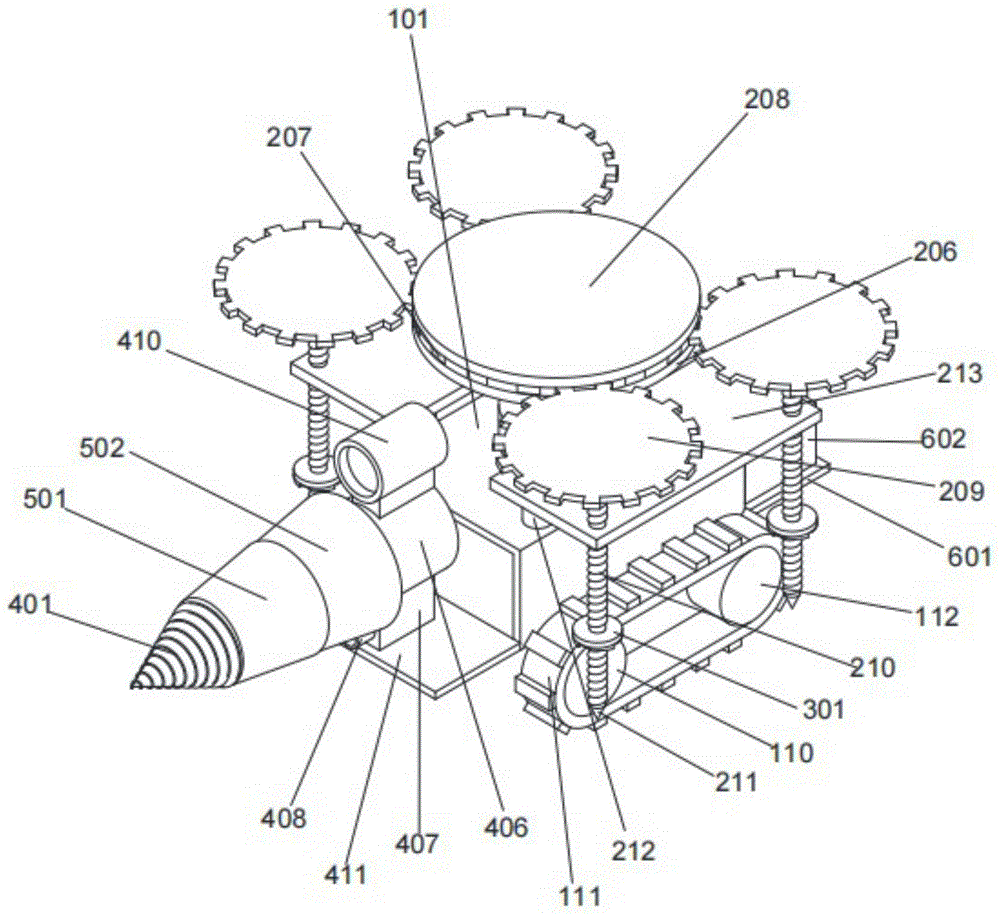
In the figure: 101 casing, 102 through groove I, 103 storage battery, 104 motor I, 105 support seat I, 106 rotating wheel I, 107 transmission belt, 108 rotating wheel II, 109 connecting shaft I, 110 rotating wheel III, 111 crawler, 112 rotating wheel IV, 113 connecting shaft II, 114 supporting rod I, 201 motor II, 202 supporting shaft I, 203 round rod I, 204 sliding rod I, 205 connecting pipe I, 206 round plate I, 207 gear I, 208 round plate II, 209 gear II, 210 threaded rod, 211 drill bit I, 212 supporting column, 213 supporting transverse plate, 301 reinforcing ring, 302 soil shoveling arc plate, 303 groove, 401 drill bit II, 402 connecting shaft III, 403 round rod II, 404 sliding rod II, 405 connecting pipe II, 406 motor III, 407 support seat II, 408 searchlight, 409 support seat III, 410 camera, 411 fixing transverse plate I, 501 protection cover I, 502 protection cover II, 503 through groove II, 504 supporting plate, 505 supporting rod II, 506 geological detector, 601 fixing transverse plate II, 408 searchlight, 409 supporting plate II, 602BIM + GIS three-dimensional model simulation device.
Detailed Description
The technical solutions in the embodiments of the present invention will be clearly and completely described below with reference to the drawings in the embodiments of the present invention, and it is obvious that the described embodiments are only a part of the embodiments of the present invention, and not all of the embodiments. All other embodiments, which can be derived by a person skilled in the art from the embodiments given herein without making any creative effort, shall fall within the protection scope of the present invention.
Referring to fig. 1-5, the present invention provides a technical solution: a tunnel construction geological detection device based on BIM + GIS comprises a shell 101, a first through groove 102 is formed in the upper surface of the inner wall of the lower side of the shell 101 in a penetrating mode, a storage battery 103 and a first supporting seat 105 are fixedly connected to the upper surface of the inner wall of the lower side of the shell 101, the first supporting seat 105 is located on the left side of the storage battery 103, a first motor 104 is fixedly connected to the upper surface of the first supporting seat 105, a first rotating wheel 106 is fixedly connected to the rear side face of a rotating shaft of the first motor 104, a driving belt 107 is rotatably connected to the circumferential side face of the first rotating wheel 106, a second rotating wheel 108 is rotatably connected to the lower end of the inner wall of the driving belt 107, the lower end of the driving belt 107 is located in the first through groove 102, a first connecting shaft 109 is fixedly connected to the center of the front side face and the rear side face of the second rotating wheel 108, a third rotating wheel 110 is fixedly connected to the front side face and the rear side face of the connecting shaft 109, a crawler 111 is rotatably connected to the right side face of the inner wall of the crawler 112, four 112 relative side centers of two runners department fixedly connected with connecting axle two 113, the equal fixedly connected with bracing piece 114 in lower surface four corners of shell 101, the side lower extreme around connecting axle one 109 and connecting axle two 113's circumference side all runs through to rotate connecting support pole one 114, and the left side of shell 101 is provided with drill bit two 401 and a protective cover 501, its characterized in that: a connecting shaft III 402 is fixedly connected to the center of the right side surface of the drill bit II 401, a round rod II 403 is fixedly connected to the center of the right side surface of the connecting shaft III 402, a slide rod II 404 is fixedly connected to the upper and lower surfaces of the round rod II 403, a connecting pipe II 405 is slidably connected to the right end surfaces of the round rod II 403 and the slide rod II 404, a motor III 406 is arranged on the right side surface of the connecting pipe II 405, the left side surface of the rotating shaft of the motor III 406 is fixedly connected to the right side surface of the protective cover II 501, the circumferential edge of the right side surface of the drill bit II 401 is fixedly connected to the left side surface of the protective cover I501, a protective cover II 502 is rotatably connected to the right end of the inner wall of the protective cover I501, a through groove II 503 is formed in the lower end of the inner wall of the protective cover II 502, a supporting plate 504 is arranged above the through groove II 503, two supporting rods 505 are fixedly connected to the four corners of the lower surface of the protective cover I501, and the inner wall of the protective cover II 502 is fixedly connected to the lower surface of the supporting rod 505, fixedly connected with geology detector 506 of lower surface center department of backup pad 504, the lower extreme of geology detector 506 is located logical groove two 503, the equal fixedly connected with 507 in upper and lower surperficial left side of motor three 406, 507 keeps away from the inner wall right-hand member edge of motor three 406's one end side fixed connection safety cover two 502, the lower fixed connection of motor three 406 has supporting seat two 407, the lower fixed connection of supporting seat two 407 has fixed diaphragm one 411, the left surface lower extreme of fixed diaphragm one 411's right flank fixed connection shell 101, the front and back side of shell 101 all is provided with threaded rod 210, the right side of shell 101 is provided with BIM + GIS three-dimensional model simulation device 602.
A second motor 201 is fixedly connected to the center of the upper surface of the casing 101, a first support shaft 202 is fixedly connected to the upper surface of a rotating shaft of the second motor 201, a first round rod 203 is fixedly connected to the center of the upper surface of the first support shaft 202, a first sliding rod 204 is fixedly connected to the circumferential side surface of the first round rod 203, a first connecting pipe 205 is slidably connected to the upper ends of the surfaces of the first round rod 203 and the first sliding rod 204, a first round plate 206 is fixedly connected to the upper surface of the first connecting pipe 205, a first gear 207 is fixedly connected to the upper surface of the first round plate 206, a second round plate 208 is fixedly connected to the upper surface of the first gear 207, a second gear 209 is engaged with the left front part, the left rear part, the right front part and the right rear part of the first gear 207, an upper surface of a threaded rod 210 is fixedly connected to the center of the lower surface of the second gear 209, a first drill bit 211 is fixedly connected to the lower surface of the threaded rod 210, support pillars 212 are fixedly connected to four corners of the upper surface of the casing 101, and a support transverse plate 213 is fixedly connected to the upper surface of the support pillars 212, the threaded surface of the threaded rod 210 penetrates through the upper surface of the threaded connection supporting transverse plate 213, the lower end of the threaded surface of the threaded rod 210 penetrates through the fixedly connected reinforcing ring 301, the circumferential edge of the lower surface of the reinforcing ring 301 is fixedly connected with a soil shoveling arc plate 302, the lower surface of the soil shoveling arc plate 302 is an inclined surface, the left side surface of the soil shoveling arc plate 302 is provided with a groove 303, the soil shoveling arc plate 302 is arranged annularly below the reinforcing ring 301, the first protective cover 501 and the second protective cover 502 are hollow circular truncated cone-shaped, the upper surface of the third motor 406 is fixedly connected with a third supporting seat 409, the upper surface of the third supporting seat 409 is fixedly connected with a camera 410, the left side surface of the second supporting seat 407 is fixedly connected with a searchlight 408, the lower surface of the BIM + GIS three-dimensional model simulation device 602 is fixedly connected with a second fixed transverse plate 601, the left side surface of the second transverse plate 601 is fixedly connected with the lower end of the right side surface of the shell 101, and the storage battery 103 is a first motor 104, a power transmission cable, The power is supplied to the second motor 201, the third motor 406 and the BIM + GIS three-dimensional model simulation device 602, the meshing part of the first gear 207 and the second gear 209 is positioned between the first circular plate 206 and the second circular plate 208, the right end of the inner wall of the first protective cover 501 is slidably connected with the left end of the outer side surface of the second protective cover 502, the problems that the existing tunnel construction geological detection is that a manual handheld geological detection instrument is used for detecting soil layers on the surface of a tunnel, the tunnel is in danger of collapse, greater threat can be caused to personal safety, and the geological detector cannot accurately measure deep soil data on the surface of the soil, so that the measurement error is large are solved.
When the device is used, the whole device is placed at the entrance of a tunnel, the whole device is controlled by remote control, the storage battery 103 supplies power to the motor I104, the motor II 201, the motor III 406 and the BIM + GIS three-dimensional model simulation device 602 through power transmission cables, the rotating shaft of the motor I104 drives the connecting shaft I109 and the rotating shaft III 110 to rotate through the rotating wheel I106, the driving belt 107 and the rotating wheel II 108, the crawler 111 rotates to enable the whole device to move forwards, the protrusions of the crawler 111 are inserted into soil to increase friction force and prevent slipping, the camera 410 transmits a photographed image to a computer of a worker, operation is convenient, the light emitted by the searchlight 408 improves road brightness, the whole device moves forwards conveniently, when the device moves to a proper position, the rotating shaft of the motor I104 stops rotating, the rotating shaft of the motor II 201 rotates to drive the supporting shaft I202, the round rod I203 and the connecting pipe I205 to rotate, and the connecting pipe I205 drives the round plate I206, The first gear 207 and the second circular plate 208 rotate, the first gear 207 simultaneously engages with the second gear 209 in four directions, the second gear 209 rotates to enable the threaded rod 210 to rotate, the supporting transverse plate 213 is fixed, the threaded surface of the threaded rod 210 penetrates through the upper surface of the supporting transverse plate 213 in threaded connection, therefore, when the threaded rod 210 rotates, the threaded rod 210 gradually moves downwards, the bottom of the first drill bit 211 drills out of the ground, the lower end of the threaded surface of the threaded rod 210 is screwed into the ground so as to fix the whole device, when the second gear 209 moves downwards, the second gear 209 presses the first circular plate 206 to enable the first circular plate 206, the first gear 207 and the second circular plate 208 to move downwards together due to the fact that the engaging part of the first gear 207 and the second gear 209 is located between the first circular plate 206 and the second circular plate 208, the surfaces of the first circular rod 203 and the first sliding rod 204 slide along the inner wall of the first connecting pipe 205, the height of the first connecting pipe 205 is reduced, the first sliding rod 204 enables the supporting shaft 202 and the first connecting pipe 205 to synchronously rotate and simultaneously to change the telescopic length, when threaded rod 210 descends to shovel soil arc board 302 bottom contact ground, shovel soil arc board 302 upper groove 303 one end is shoveled earth, and earth gets into in the recess 303 until filling up recess 303 inner space, and reinforcement ring 301 bottom contact ground this moment, chucking in the whole screw in earth of shovel soil arc board 302, the screw thread of cooperation threaded rod 210 further improves the steadiness of whole device, and the device takes place to remove when avoiding follow-up drilling to the tunnel inner wall.
After the device is fixed and stable, a rotating shaft of a motor III 406 rotates to drive a connecting pipe II 405, a sliding rod II 404, a round rod II 403, a connecting shaft III 402 and a drill bit II 401 to rotate, the tip end of the drill bit II 401 is inserted into soil on the inner wall of a tunnel, when the drill bit II 401 rotates, spiral grains on the drill bit II 401 are screwed into the soil to drive the drill bit II 401 to move towards the left side, so that the drill bit II is inserted into the deep soil, a protective cover I501 rotates and moves along with the drill bit II 401 while the drill bit II 401 is rotatably inserted into a soil drill hole, the drilled soil is supported to form a complete hole, a protective cover II 502 is fixed on the motor III 406 through a 507 and fixed, the right end of the inner wall of the protective cover I501 rotates on the surface of the left end of the outer side of the protective cover II 502 and gradually slides towards the left side, when the protective cover I moves to the through groove II 503 below the protective cover II 502 to expose, the geological detector 506 is exposed to measure and record the soil data on the outer side, then the data is sent to a BIM + GIS three-dimensional model simulation device 602 for analysis and processing to obtain a three-dimensional visual graph and generate an advanced geological forecast automatic report, then the data is sent to a computer of a worker to complete detection, then a rotating shaft of a motor II 201 rotates to pull out a threaded rod 210 from soil, as the lower surface of a soil shoveling arc plate 302 is an inclined surface and is annularly arranged under a reinforcing ring 301, when the threaded rod 210 is reversely pulled out of the soil, the soil shoveling arc plate 302 can be smoothly pulled out of the soil, the pulling-out is easier while the fixing effect is improved, the use is convenient, a part of a gear II 209 meshed with the gear I207 pushes up a circular plate II 208 upwards to enable a connecting pipe I205 to ascend to return to an initial position, then the motor I104 drives a crawler 111 to rotate to enable the device to move, the drill bit II 401 is pulled out of a hole, and as the protective cover I501 and the protective cover II 502 support the soil during drilling, make the hole inner wall complete and firm, thereby it is easier to make two drill bits 401 extract, the shape of safety cover one 501 and safety cover two 502 is hollow round platform shape and right-hand member diameter is greater than the left end, the earth that will bore out pushes the extrusion all around in drilling, further improve the steadiness in hole, make things convenient for two drill bits 401 to extract, and safety cover one 501 and safety cover two 502 can protect its inner structure not to be stained with by earth and cause the jam trouble, reduce the device trouble, when geology detector 506 surveyed earth around, nearer loam layer is compressed tightly by the extrusion of safety cover one 501 and safety cover two 502, farther loam layer keeps original state, make geology detector 506 can detect two kinds of data simultaneously, data analysis to follow-up tunnel excavation provides drilling analog data, further improve the effect of surveying.
Although embodiments of the present invention have been shown and described, it will be appreciated by those skilled in the art that changes, modifications, substitutions and alterations can be made in these embodiments without departing from the principles and spirit of the invention, the scope of which is defined in the appended claims and their equivalents.