CN113229673A - Good student apartment of security is with multi-functional bed - Google Patents
Good student apartment of security is with multi-functional bed Download PDFInfo
- Publication number
- CN113229673A CN113229673A CN202110537267.4A CN202110537267A CN113229673A CN 113229673 A CN113229673 A CN 113229673A CN 202110537267 A CN202110537267 A CN 202110537267A CN 113229673 A CN113229673 A CN 113229673A
- Authority
- CN
- China
- Prior art keywords
- bottom plate
- rod
- spring
- wedge
- bed
- Prior art date
- Legal status (The legal status is an assumption and is not a legal conclusion. Google has not performed a legal analysis and makes no representation as to the accuracy of the status listed.)
- Granted
Links
- 230000001681 protective effect Effects 0.000 claims description 6
- 230000003139 buffering effect Effects 0.000 claims description 5
- 230000000694 effects Effects 0.000 abstract description 12
- 230000006870 function Effects 0.000 description 3
- 238000005034 decoration Methods 0.000 description 2
- 238000012986 modification Methods 0.000 description 2
- 230000004048 modification Effects 0.000 description 2
- 208000027418 Wounds and injury Diseases 0.000 description 1
- 230000002146 bilateral effect Effects 0.000 description 1
- 230000006378 damage Effects 0.000 description 1
- 230000007547 defect Effects 0.000 description 1
- 238000010586 diagram Methods 0.000 description 1
- 238000003912 environmental pollution Methods 0.000 description 1
- 208000014674 injury Diseases 0.000 description 1
Images


Classifications
-
- A—HUMAN NECESSITIES
- A47—FURNITURE; DOMESTIC ARTICLES OR APPLIANCES; COFFEE MILLS; SPICE MILLS; SUCTION CLEANERS IN GENERAL
- A47C—CHAIRS; SOFAS; BEDS
- A47C19/00—Bedsteads
- A47C19/22—Combinations of bedsteads with other furniture or with accessories, e.g. with bedside cabinets
-
- A—HUMAN NECESSITIES
- A47—FURNITURE; DOMESTIC ARTICLES OR APPLIANCES; COFFEE MILLS; SPICE MILLS; SUCTION CLEANERS IN GENERAL
- A47C—CHAIRS; SOFAS; BEDS
- A47C21/00—Attachments for beds, e.g. sheet holders, bed-cover holders; Ventilating, cooling or heating means in connection with bedsteads or mattresses
-
- A—HUMAN NECESSITIES
- A47—FURNITURE; DOMESTIC ARTICLES OR APPLIANCES; COFFEE MILLS; SPICE MILLS; SUCTION CLEANERS IN GENERAL
- A47C—CHAIRS; SOFAS; BEDS
- A47C29/00—Nets for protection against insects in connection with chairs or beds; Bed canopies
- A47C29/003—Bed canopies
Landscapes
- Life Sciences & Earth Sciences (AREA)
- Pest Control & Pesticides (AREA)
- Invalid Beds And Related Equipment (AREA)
Abstract
The invention relates to a multifunctional bed, in particular to a multifunctional bed with good safety for student apartments. The technical problem of the invention is that: provided is a multifunctional bed for student apartment, which can place books and articles, has the function of protecting personal privacy, has good shielding effect and good safety. The technical scheme of the invention is as follows: a multifunctional bed with good safety for student apartments comprises a bottom plate and first support rods, wherein the first support rods are symmetrically arranged on two sides of the bottom plate; a guardrail is arranged on one side of the bottom plate; the top of the bottom plate is provided with a buffer component; the other side of the bottom plate is provided with a protection component. According to the invention, the pull rod moves downwards to drive the second wedge-shaped block to move downwards, the fifth spring is compressed, so that the bed curtain is not blocked by the second wedge-shaped block, and the bed curtain is driven to expand leftwards under the action of the fourth spring, so that the effect of protecting the personal privacy of students is achieved, and the shielding effect is achieved.
Description
Technical Field
The invention relates to a multifunctional bed, in particular to a multifunctional bed with good safety for student apartments.
Background
As is well known, school is in order to save student's area of occupation of bed, traditional student's apartment bed, all be the bunk beds of putting on and off the shelf, generally the bed of going on and off the bed only has a single sleeping space, article at ordinary times, books, learning tools etc. do not have the department and put, especially sleep at the student of putting on the bed, go to have a rest easily, it is just inconvenient to get off, if the bedstead is more smooth, the student takes place the incident easily when getting off, cause the injury, and when the student was eaten at the upper berth, lazily get off the bed and throw away rubbish, will have the upper berth to rubbish earlier temporarily, so not only cause environmental pollution, can also lead to the whole environment of dormitory unclean scheduling problem to exist.
In view of the above, there is a need to design a multifunctional bed for student apartment with good safety, which can be used for placing books and articles, and has the function of protecting personal privacy, and a better shielding effect, so as to solve the above problems.
Disclosure of Invention
In order to overcome the defects that the traditional student apartment beds are bunk beds with upper and lower frames and only one single sleeping space exists in the upper and lower beds, the invention has the technical problems that: provided is a multifunctional bed for student apartment, which can place books and articles, has the function of protecting personal privacy, has good shielding effect and good safety.
The technical scheme of the invention is as follows: a multifunctional bed with good safety for student apartments comprises: the bottom plate is provided with a first support rod symmetrically on two sides; a guardrail is arranged on one side of the bottom plate; the top of the bottom plate is provided with a buffer component; the other side of the bottom plate is provided with a protection component.
Further, the buffer assembly includes: four first guide rods are symmetrically arranged on two sides of the top of the bottom plate; the top of the first guide rod is connected with a first spring, and a bed plate is connected between the upper ends of the first springs.
Further, the protection component comprises: the other side of the bottom plate is provided with a protective rod in a sliding manner; the second spring is symmetrically arranged between the bottom of the protective rod and the bottom plate; the first wedge block is arranged on one side of the bottom plate in a sliding mode and matched with the protection rod; and a third spring is arranged between the first wedge-shaped block and the bottom plate.
Further, still include the storage component, the storage component includes: the box door is rotatably arranged on one side of the upper part of the bottom plate; the hinge is symmetrically connected between the box door and the bottom plate; the limiting blocks are symmetrically arranged on one side of the upper part of the bottom plate and are matched with the box door; a cabinet door is rotatably arranged on one side of the upper part of the bottom plate; the handles are arranged on one side of the cabinet door and one side of the cabinet door; the first clamping block is arranged on the other side of the upper part of the bottom plate in a sliding mode and matched with the box door.
Further, still include and shelter from the subassembly, shelter from the subassembly including: a second guide rod is arranged between one side and the other side of the upper part of the bottom plate; one side of the second guide rod is slidably provided with the bed curtain; a fourth spring is arranged between the bed curtain and the bottom plate and sleeved on the upper side of the first guide rod; a second support rod is arranged on one side of the upper part of the second guide rod; the second support rod is provided with a second wedge block in a sliding manner, and the second wedge block is matched with the bed curtain; a fifth spring is arranged between the second wedge-shaped block and the second support rod and sleeved on the second support rod; the pull rod is arranged at the bottom of the second wedge-shaped block and matched with the first wedge-shaped block; and a sixth spring is arranged between the pull rod and the first guide rod and sleeved on the second guide rod.
Further, still including placing the subassembly, place the subassembly including: one side of the bottom plate is symmetrically provided with a rotating first rotating rod; a second rotating rod is symmetrically and rotatably arranged on one side of the bottom plate; the placing plate is rotatably arranged between the second rotating rod and the first rotating rod; the torsional springs are symmetrically arranged between the first rotating rod and the bottom plate; the upper part of one side of the bottom plate is provided with a second clamping block in a sliding manner, and the placing plate is matched with the second clamping block; a seventh spring is symmetrically arranged between the second clamping block and the bottom plate; a third guide rod is symmetrically arranged on one side inside the bottom plate; a wedge-shaped rod is arranged between the upper sides of the third guide rods in a sliding manner and matched with the second clamping block; eighth springs are symmetrically arranged between the wedge-shaped rods and the bottom plate and sleeved on the third guide rods; the clamping rod is arranged on one side of the upper portion of the bottom plate in a sliding mode and matched with the wedge-shaped rod.
Furthermore, the device also comprises a clamping assembly, wherein the clamping assembly is arranged on one side of the upper part of the bottom plate.
Further, still include clamping component, clamping component includes: the other side of the upper part of the bottom plate is symmetrically provided with a third supporting rod up and down; a clamping plate is arranged between the third supporting rods in a sliding manner; a pull handle is arranged on one side of the clamping plate; ninth springs are symmetrically arranged between the clamping plate and the bottom plate, and the ninth springs are all sleeved on the third supporting rod.
Compared with the prior art, the invention has the following advantages: 1. according to the invention, the pull rod moves downwards to drive the second wedge-shaped block to move downwards, the fifth spring is compressed, so that the bed curtain is not blocked by the second wedge-shaped block, and the bed curtain is driven to expand leftwards under the action of the fourth spring, so that the effect of protecting the personal privacy of students is achieved, and the shielding effect is achieved.
2. Through the effect that the seventh spring resets, drive the second fixture block and block left and place the board, increase the stability of placing the board, at this moment, remove the kelly left again and block the wedge pole, so, the student alright be stable study placing the board on, improve the efficiency that the student studied.
3. Through increasing the back gradually at books quantity for splint and pulling the rearward movement, the ninth spring is compressed, and splint press from both sides books tightly, prevents that books from dropping downwards, and at the effect of splint, not only can press from both sides tight books and avoid dropping, can also make books put neatly, increase pleasing to the eye.
Drawings
Fig. 1 is a schematic perspective view of the present invention.
FIG. 2 is an enlarged view of the present invention A.
Fig. 3 is a partial perspective view of the present invention.
Fig. 4 is a use state diagram of the present invention.
FIG. 5 is a schematic cross-sectional view of FIG. 3 according to the present invention.
FIG. 6 is an enlarged schematic view of invention B.
Fig. 7 is a schematic structural view of the shield assembly and the storage assembly of the present invention.
FIG. 8 is an enlarged schematic view of invention C.
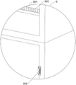
FIG. 9 is an enlarged schematic view of invention D.
FIG. 10 is an enlarged schematic view of invention E.
Reference numbers in the drawings: 1_ first support bar, 2_ base plate, 3_ guard bar, 4_ cushion assembly, 401_ first guide bar, 402_ bed plate, 403_ first spring, 5_ guard assembly, 501_ guard bar, 502_ second spring, 503_ first wedge, 504_ third spring, 6_ storage assembly, 601_ hinge, 602_ door, 603_ stop block, 604_ cabinet door, 605_ handle, 606_ first catch, 7_ shield assembly, 701_ second guide bar, 702_ bed curtain, 703_ fourth spring, 704_ second support bar, 705_ second wedge, 706_ fifth spring, 707_ pull bar, 708_ sixth spring, 8_ placing assembly, 801_ first rotating bar, 802_ second rotating bar, 803_ placing plate, 804_ torsion spring, 805_ second catch 806, 806_ seventh spring, 807_ third guide bar, 808_ wedge bar, 809_ eighth spring, 810_ catch bar, 9_ clamping assembly, 901_ splint, 902_ pull handle, 903_ third support rod, 904_ ninth spring.
Detailed Description
The technical solutions in the embodiments of the present invention will be clearly and completely described below with reference to the drawings in the embodiments of the present invention, and it is obvious that the described embodiments are only a part of the embodiments of the present invention, and not all of the embodiments. All other embodiments, which can be derived by a person skilled in the art from the embodiments given herein without making any creative effort, shall fall within the protection scope of the present invention.
Example 1
A multifunctional bed with good safety for student apartments is shown in figures 1-5 and comprises first supporting rods 1, a bottom plate 2, guardrails 3, buffering components 4 and a protection component 5, wherein the first supporting rods 1 are symmetrically arranged on the front side and the rear side of the bottom plate 2 in a bilateral mode, the guardrail 3 is arranged on the right side of the bottom plate 2, the buffering components 4 are arranged on the top of the bottom plate 2, and the protection component 5 is arranged on the front side of the bottom plate 2.
The buffering component 4 comprises a first guide rod 401, a bed plate 402 and a first spring 403, four first guide rods 401 are symmetrically arranged on the front side and the rear side of the top of the bottom plate 2, the top of each first guide rod 401 is connected with the first spring 403, and the bed plate 402 is connected between the upper ends of the first springs 403.
The protection component 5 comprises a protection rod 501, a second spring 502, a first wedge-shaped block 503 and a third spring 504, the protection rod 501 is arranged in a sliding mode in front of the bottom plate 2, the second spring 502 is symmetrically arranged between the bottom of the protection rod 501 and the bottom plate 2, the first wedge-shaped block 503 is arranged in a sliding mode in front of the right of the bottom plate 2, the first wedge-shaped block 503 is matched with the protection rod 501, and the third spring 504 is arranged between the first wedge-shaped block 503 and the bottom plate 2.
In the original state, the first wedge-shaped block 503 blocks the protection rod 501, the second spring 502 is compressed, when a student needs to use for rest, the student moves the first wedge-shaped block 503 to the right, the third spring 504 is compressed, the first wedge-shaped block 503 is separated from the protection rod 501, the protection rod 501 is driven to move upwards under the action of the reset of the second spring 502, then the first wedge-shaped block 503 is loosened, the first wedge-shaped block 503 is driven to move leftwards under the action of the third spring 504 for reset, then the student can lie on the bed plate 402, the first spring 403 has the buffering effect, comfort is increased when the student lies on the bed plate 402 for rest, under the action of the protection rod 501, the student is prevented from falling on the ground when sleeping, the protection effect is achieved, safety of the student during sleeping is improved, after the student gets up, the protection rod 501 is manually contacted with the first wedge-shaped block 503 downwards, the second spring 502 is compressed, after the protection rod 501 smoothly passes through the first wedge-shaped block 503 by the third spring 504, the first wedge-shaped block 503 catches the protection rod 501.
Example 2
On the basis of embodiment 1, as shown in fig. 6-10, the portable electronic device further includes a storage assembly 6, the storage assembly 6 includes a hinge 601, a door 602, a limiting block 603, a door 604, a handle 605 and a first clamping block 606, the door 602 is rotatably disposed on the left side of the upper portion of the bottom plate 2, the hinge 601 is symmetrically connected between the door 602 and the bottom plate 2, the limiting blocks 603 are symmetrically disposed on the front and back of the left side of the upper portion of the bottom plate 2, the limiting blocks 603 are both matched with the door 602, the door 604 is rotatably disposed on the front left side of the upper portion of the bottom plate 2, the handle 605 is disposed on the right side of the door 604 and the handle 602, the first clamping block 606 is slidably disposed on the left and right sides of the upper portion of the bottom plate 2, and the first clamping block 606 is matched with the door 602.
When the multifunctional bed is needed to be used, a student holds the handle 605 at the upper side to open the cabinet door 604 clockwise, clothes or articles for daily use can be stored in the cabinet door or taken out of the cabinet door, when the multifunctional bed is not used, the cabinet door 604 is manually rotated counterclockwise to be closed, when learning tools or books need to be stored, the student holds the handle 605 at the lower side to open the cabinet door 602 clockwise, the cabinet door 602 does not continue to rotate under the action of the limiting block 603, at the moment, the student can store or take out the learning tools and the books, when the learning tools are not needed, the student manually rotates the cabinet door 602 counterclockwise to be closed, and then the first clamping block 606 is blocked to move forward the cabinet door 602, so that the effect of fixing the cabinet door 602 is achieved.
The utility model also comprises a shielding component 7, the shielding component 7 comprises a second guide rod 701, a bed curtain 702, a fourth spring 703, a second support rod 704, a second wedge block 705, a fifth spring 706, a pull rod 707 and a sixth spring 708, the second guide rod 701 is arranged between the left side and the right side of the upper part of the bottom plate 2, the bed curtain 702 is arranged on the upper right side of the second guide rod 701 in a sliding way, the fourth spring 703 is arranged between the bed curtain 702 and the bottom plate 2, the fourth spring 703 is sleeved on the upper side of the first guide rod 401, the second support rod 704 is arranged on the right side of the upper part of the second guide rod 701, the second wedge block 705 is arranged on the second support rod 704 in a sliding way, the second wedge block 705 is matched with the bed curtain 702, the fifth spring 706 is arranged between the second wedge block 704 and the second support rod 706, the pull rod 707 is arranged at the bottom of the second wedge block 705, the pull rod 707 is matched with the first wedge block 503, the sixth spring 708 is arranged between the pull rod 707 and the first guide rod 401, the sixth spring 708 is fitted over the second guide bar 701.
Under the original state, the bed curtain 702 is in a contracted state, the fourth spring 703 is in a compressed state, when a student needs to rest, the student moves the pull rod 707 downwards to contact with the first wedge-shaped block 503, the sixth spring 708 is compressed, the pull rod 707 pulls the first wedge-shaped block 503 to the right, simultaneously the pull rod 707 moves downwards to drive the second wedge-shaped block 705 to move downwards, the fifth spring 706 is compressed, so that the second wedge-shaped block 705 does not block the bed curtain 702, under the action of the fourth spring 703, the bed curtain 702 is driven to expand leftwards, the function of protecting the individual privacy of the student is achieved, at the moment, the pull rod 707 is released, under the action of the sixth spring 708, the pull rod 707 resets upwards, under the action of the fifth spring 706, the second wedge-shaped block resets upwards, when the student gets up to bed, when the student does not need to use the multifunctional bed, the bed curtain 702 is manually contracted, the fourth spring 703 is moved rightwards to be compressed, so that the bed curtain 702 contacts with the second wedge-shaped block 705, the second wedge 705 is driven downward and the fifth spring 706 is compressed, and after the bed curtain 702 is separated from the second wedge 705, the second wedge 705 is driven upward to block the bed curtain 702 by the fifth spring 706, thereby facilitating air circulation.
The device also comprises a placing assembly 8, the placing assembly 8 comprises a first rotating rod 801, a second rotating rod 802, a placing plate 803, a torsion spring 804, a second clamping block 805, a seventh spring 806, a third guide rod 807, a wedge-shaped rod 808, an eighth spring 809 and a clamping rod 810, the first rotating rod 801 is symmetrically arranged at the front and back of the left lower side of the bottom plate 2 in a rotating mode, the second rotating rod 802 is symmetrically arranged at the front and back of the left upper side of the bottom plate 2 in a rotating mode, the placing plate 803 is rotationally arranged between the second rotating rod 802 and the first rotating rod 801 in a rotating mode, the torsion spring 804 is symmetrically arranged between the first rotating rod 801 and the bottom plate 2, the second clamping block 805 is slidably arranged at the upper part of the left side of the bottom plate 2, the placing plate 803 is matched with the second clamping block 805, the seventh spring 806 is symmetrically arranged between the second clamping block and the bottom plate 2, the third guide rod 807 is symmetrically arranged at the left front side in the bottom plate 2, the wedge-shaped rod 808 is slidably arranged between the upper sides of the third guide rod 807, the wedge-shaped rod 808 is matched with the second clamping block 805, eighth springs 809 are symmetrically arranged between the wedge-shaped rods 808 and the bottom plate 2, the eighth springs 809 are sleeved on the third guide rods 807, clamping rods 810 are arranged on the left front side of the upper portion of the bottom plate 2 in a sliding mode, and the clamping rods 810 are matched with the wedge-shaped rods 808.
In the original state, the seventh spring 806 is compressed, the wedge-shaped rod 808 presses the second latch 805, when a student needs to learn, the manual placing plate 803 is rotated counterclockwise to open, so as to drive the first rotating rod 801 to rotate counterclockwise, further to drive the second rotating rod 802 to rotate clockwise, the torsion spring 804 deforms, so that the placing plate 803 is aligned with the second latch 805, then the wedge-shaped rod 808 is moved upward to separate from the second latch 805, the eighth spring 809 is stretched, at this time, the seventh spring 806 is reset to drive the second latch 805 to move leftward to clamp the placing plate 803, the second latch 805 is driven to clamp the placing plate 803 leftward, the stability of the placing plate 803 is increased, at this time, the clamping rod 810 is moved leftward to clamp the wedge-shaped rod 808, so that the student can stably learn on the placing plate 803, when the student does not need to learn, the clamping rod 810 is manually separated from the wedge-shaped rod 808 rightward, at the action of the eighth spring 809, the wedge-shaped rod 808 is driven to move downwards to be in contact with the second clamping block 805, the wedge-shaped rod 808 presses the second clamping block 805 leftwards, the seventh spring 806 is compressed, the second clamping block 805 is separated from the placing plate 803, the first rotating rod 801 and the placing plate 803 are driven to rotate clockwise to reset under the action of the torsion spring 804, the second rotating rod 802 is driven to rotate anticlockwise to reset, and the placing plate 803 is closed.
The clamping device is characterized by further comprising a clamping assembly 9, wherein the clamping assembly 9 comprises a clamping plate 901, a pull handle 902, a third supporting rod 903 and a ninth spring 904, the third supporting rod 903 is symmetrically arranged on the left rear side of the upper portion of the bottom plate 2 in an up-down mode, the clamping plate 901 is arranged between the third supporting rods 903 in a sliding mode, the ninth spring 904 is symmetrically arranged between the clamping plate 901 and the bottom plate 2, the pull handle 902 is arranged on the right side of the clamping plate 901, and the ninth spring 904 is sleeved on the third supporting rod 903.
When the student need put books, the student can place many books and contact with splint 901 at bottom plate 2 left rear side, behind books quantity increase gradually for splint 901 with draw handle 902 to remove backward, ninth spring 904 is compressed, and splint 901 presss from both sides books tightly, prevents that books from dropping downwards, reduces the back gradually when books quantity, at the effect of ninth spring 904, drives splint 901 and draws handle 902 to reset forward.
The foregoing is only a preferred embodiment of the present invention, and it should be noted that, for those skilled in the art, various modifications and decorations can be made without departing from the principle of the present invention, and these modifications and decorations should also be regarded as the protection scope of the present invention.
Claims (8)
1. The utility model provides a good multi-functional bed is used in student's apartment of security which characterized in that, including:
the supporting device comprises a bottom plate (2) and first supporting rods (1), wherein the first supporting rods (1) are symmetrically arranged on two sides of the bottom plate (2);
a guardrail (3) is arranged on one side of the bottom plate (2);
the top of the bottom plate (2) is provided with a buffer component (4);
the other side of the protective component (5) and the bottom plate (2) is provided with the protective component (5).
2. A multi-purpose bed for student's apartment with good safety according to claim 1, characterized in that the buffering unit (4) comprises:
four first guide rods (401) are symmetrically arranged on two sides of the top of the bottom plate (2); the top of the bed plate (402), the top of the first guide rod (401) is connected with a first spring (403), and the bed plate (402) is connected between the upper ends of the first spring (403).
3. A multi-purpose bed for student's apartment with good safety according to claim 2, characterized in that the guard member (5) comprises:
the other side of the bottom plate (2) is provided with a protective rod (501) in a sliding manner;
the second spring (502) is symmetrically arranged between the bottom of the protective rod (501) and the bottom plate (2); the first wedge-shaped block (503) is arranged on one side of the bottom plate (2) in a sliding mode, and the first wedge-shaped block (503) is matched with the protection rod (501);
and a third spring (504), wherein the third spring (504) is arranged between the first wedge-shaped block (503) and the bottom plate (2).
4. A multi-purpose bed for student's apartment with good safety according to claim 3, characterized in that it further comprises a storage unit (6), the storage unit (6) comprising:
the refrigerator door (602), one side of the upper part of the bottom plate (2) is rotatably provided with the refrigerator door (602);
the hinge (601) is symmetrically connected between the box door (602) and the bottom plate (2);
the limiting blocks (603) are symmetrically arranged on one side of the upper part of the bottom plate (2), and the limiting blocks (603) are matched with the box door (602);
a cabinet door (604), wherein one side of the upper part of the bottom plate (2) is rotatably provided with the cabinet door (604);
the handles (605) are arranged on one side of the cabinet door (604) and one side of the cabinet door (602);
the first clamping block (606) is arranged on the other side of the upper part of the bottom plate (2) in a sliding mode, and the first clamping block (606) is matched with the box door (602).
5. A multi-purpose bed for student's apartment with good safety according to claim 4, characterized by further comprising a shielding member (7), the shielding member (7) comprising:
a second guide rod (701), wherein the second guide rod (701) is arranged between one side and the other side of the upper part of the bottom plate (2);
the bed curtain (702) is arranged on one side of the second guide rod (701) in a sliding mode;
a fourth spring (703), the fourth spring (703) is arranged between the bed curtain (702) and the bottom plate (2), and the fourth spring (703) is sleeved on the upper side of the first guide rod (401);
a second support rod (704), wherein one side of the upper part of the second guide rod (701) is provided with the second support rod (704); the second wedge block (705) is arranged on the second support rod (704) in a sliding mode, and the second wedge block (705) is matched with the bed curtain (702);
a fifth spring (706), wherein the fifth spring (706) is arranged between the second wedge block (705) and the second support rod (704), and the fifth spring (706) is sleeved on the second support rod (704);
the bottom of the second wedge-shaped block (705) is provided with a pull rod (707), and the pull rod (707) is matched with the first wedge-shaped block (503);
and a sixth spring (708), wherein the sixth spring (708) is arranged between the pull rod (707) and the first guide rod (401), and the sixth spring (708) is sleeved on the second guide rod (701).
6. A multi-purpose bed for student's apartment with good safety according to claim 5, characterized by further comprising a placing module (8), the placing module (8) comprising:
the first rotating rod (801), one side of the bottom plate (2) is symmetrically provided with the first rotating rod (801) in a rotating mode;
a second rotating rod (802), wherein the second rotating rod (802) is symmetrically and rotatably arranged on one side of the bottom plate (2);
a placing plate (803), wherein the placing plate (803) is rotatably arranged between the second rotating rod (802) and the first rotating rod (801);
torsion springs (804) are symmetrically arranged between the first rotating rod (801) and the bottom plate (2);
a second clamping block (805), wherein the upper part of one side of the bottom plate (2) is provided with the second clamping block (805) in a sliding manner, and the placing plate (803) is matched with the second clamping block (805);
a seventh spring (806), wherein the seventh spring (806) is symmetrically arranged between the second clamping block (805) and the bottom plate (2);
a third guide rod (807), wherein the third guide rod (807) is symmetrically arranged at one side inside the bottom plate (2);
a wedge-shaped rod (808) is arranged between the upper sides of the third guide rods (807) in a sliding manner, and the wedge-shaped rod (808) is matched with the second clamping block (805);
eighth springs (809), the eighth springs (809) are symmetrically arranged between the wedge-shaped rods (808) and the bottom plate (2), and the eighth springs (809) are sleeved on the third guide rods (807);
the clamping rod (810) is arranged on one side of the upper portion of the bottom plate (2) in a sliding mode, and the clamping rod (810) is matched with the wedge-shaped rod (808).
7. A multi-purpose bed for student's apartment with excellent safety according to claim 6, characterized by further comprising a clamping unit (9), wherein the clamping unit (9) is provided on the upper side of the bottom plate (2).
8. A multi-purpose bed for student's apartment with good safety according to claim 6, characterized in that the clamping unit (9) comprises:
the other side of the upper part of the bottom plate (2) is symmetrically provided with a third supporting rod (903) up and down;
the clamping plate (901) is arranged between the third supporting rods (903) in a sliding manner;
a pull handle (902) is arranged on one side of the splint (901);
ninth springs (904) are symmetrically arranged between the clamping plate (901) and the bottom plate (2), and the ninth springs (904) are all sleeved on the third supporting rod (903).
Priority Applications (1)
| Application Number | Priority Date | Filing Date | Title |
|---|---|---|---|
| CN202110537267.4A CN113229673B (en) | 2021-05-18 | 2021-05-18 | Good student apartment of security is with multi-functional bed |
Applications Claiming Priority (1)
| Application Number | Priority Date | Filing Date | Title |
|---|---|---|---|
| CN202110537267.4A CN113229673B (en) | 2021-05-18 | 2021-05-18 | Good student apartment of security is with multi-functional bed |
Publications (2)
| Publication Number | Publication Date |
|---|---|
| CN113229673A true CN113229673A (en) | 2021-08-10 |
| CN113229673B CN113229673B (en) | 2023-01-10 |
Family
ID=77134970
Family Applications (1)
| Application Number | Title | Priority Date | Filing Date |
|---|---|---|---|
| CN202110537267.4A Active CN113229673B (en) | 2021-05-18 | 2021-05-18 | Good student apartment of security is with multi-functional bed |
Country Status (1)
| Country | Link |
|---|---|
| CN (1) | CN113229673B (en) |
Cited By (3)
| Publication number | Priority date | Publication date | Assignee | Title |
|---|---|---|---|---|
| CN114228798A (en) * | 2021-12-23 | 2022-03-25 | 唐建华 | Equipment convenient to store and transport electronic components |
| CN115054085A (en) * | 2022-07-07 | 2022-09-16 | 江西省焦点实业有限公司 | Dormitory multi-purpose apartment bed |
| CN115517872A (en) * | 2022-05-25 | 2022-12-27 | 赵娜娜 | Obstetrical department is with multi-functional nursing bed |
Citations (10)
| Publication number | Priority date | Publication date | Assignee | Title |
|---|---|---|---|---|
| CN205306400U (en) * | 2015-12-30 | 2016-06-15 | 雷艺琳 | Student uses multi -functional book end |
| CN106724131A (en) * | 2017-04-01 | 2017-05-31 | 贵州大学 | A kind of student's multifunctional book stand |
| CN209733200U (en) * | 2019-03-13 | 2019-12-06 | 中山市宝晨婴童用品有限公司 | Lifting bed guardrail capable of being operated by single hand |
| CN111990822A (en) * | 2020-08-31 | 2020-11-27 | 江西新汉力实业有限公司 | Adjustable good student apartment bed of privacy nature |
| CN112273919A (en) * | 2020-10-31 | 2021-01-29 | 江西和兴教育装备有限公司 | Intelligent dropproof shading student bed |
| CN112515402A (en) * | 2020-12-10 | 2021-03-19 | 涂林勇 | Students 'dormitory is with student's bed that has privacy protection |
| CN112535379A (en) * | 2020-11-18 | 2021-03-23 | 南城弘天实业有限公司 | Storage type furniture apartment bed |
| CN112545242A (en) * | 2020-11-18 | 2021-03-26 | 南城弘天实业有限公司 | Apartment bed with safety guardrail and storage function |
| CN112617503A (en) * | 2020-12-02 | 2021-04-09 | 陆维莉 | Folding apartment bed of over-and-under type |
| CN112690603A (en) * | 2020-12-10 | 2021-04-23 | 江西卓尔金属设备集团有限公司 | Student apartment bed with folding books containing box |
-
2021
- 2021-05-18 CN CN202110537267.4A patent/CN113229673B/en active Active
Patent Citations (10)
| Publication number | Priority date | Publication date | Assignee | Title |
|---|---|---|---|---|
| CN205306400U (en) * | 2015-12-30 | 2016-06-15 | 雷艺琳 | Student uses multi -functional book end |
| CN106724131A (en) * | 2017-04-01 | 2017-05-31 | 贵州大学 | A kind of student's multifunctional book stand |
| CN209733200U (en) * | 2019-03-13 | 2019-12-06 | 中山市宝晨婴童用品有限公司 | Lifting bed guardrail capable of being operated by single hand |
| CN111990822A (en) * | 2020-08-31 | 2020-11-27 | 江西新汉力实业有限公司 | Adjustable good student apartment bed of privacy nature |
| CN112273919A (en) * | 2020-10-31 | 2021-01-29 | 江西和兴教育装备有限公司 | Intelligent dropproof shading student bed |
| CN112535379A (en) * | 2020-11-18 | 2021-03-23 | 南城弘天实业有限公司 | Storage type furniture apartment bed |
| CN112545242A (en) * | 2020-11-18 | 2021-03-26 | 南城弘天实业有限公司 | Apartment bed with safety guardrail and storage function |
| CN112617503A (en) * | 2020-12-02 | 2021-04-09 | 陆维莉 | Folding apartment bed of over-and-under type |
| CN112515402A (en) * | 2020-12-10 | 2021-03-19 | 涂林勇 | Students 'dormitory is with student's bed that has privacy protection |
| CN112690603A (en) * | 2020-12-10 | 2021-04-23 | 江西卓尔金属设备集团有限公司 | Student apartment bed with folding books containing box |
Cited By (3)
| Publication number | Priority date | Publication date | Assignee | Title |
|---|---|---|---|---|
| CN114228798A (en) * | 2021-12-23 | 2022-03-25 | 唐建华 | Equipment convenient to store and transport electronic components |
| CN115517872A (en) * | 2022-05-25 | 2022-12-27 | 赵娜娜 | Obstetrical department is with multi-functional nursing bed |
| CN115054085A (en) * | 2022-07-07 | 2022-09-16 | 江西省焦点实业有限公司 | Dormitory multi-purpose apartment bed |
Also Published As
| Publication number | Publication date |
|---|---|
| CN113229673B (en) | 2023-01-10 |
Similar Documents
| Publication | Publication Date | Title |
|---|---|---|
| CN113229673B (en) | Good student apartment of security is with multi-functional bed | |
| CN115067713A (en) | Baby bed | |
| CN112586929B (en) | Dormitory bed with adjustable storage function | |
| US4450597A (en) | Convertible bed | |
| CN113142879B (en) | Foldable combined student apartment bed | |
| CN210748306U (en) | Dormitory apartment bed with protection function | |
| CN209950840U (en) | From bunk student bed of taking desk chair | |
| CN112137315A (en) | Multifunctional bedside cabinet | |
| CN110123052B (en) | Telescopic folding bed-chair dual-purpose device | |
| CN114431642A (en) | Can supply storage desk of noon break | |
| CN112971446A (en) | Mosquito-proof university student dormitory function bed | |
| US2856612A (en) | Convertible cabinet, bed, and sofa | |
| CN211092567U (en) | Multifunctional hidden storage cabinet | |
| CN113425117A (en) | Foldable student apartment bed convenient to accomodate books | |
| CN112294028B (en) | Kindergarten crib with light isolation function | |
| CN220494665U (en) | Multifunctional apartment bed | |
| US2078975A (en) | Sun stall | |
| CN215993152U (en) | Desk with shockproof function | |
| CN207461766U (en) | A kind of Multifunctional commodity cabinet | |
| CN220157957U (en) | Child bed convenient to fold and store | |
| CN215076980U (en) | Double-deck bed convenient for storing articles | |
| CN216797091U (en) | Noon break bed for student rest | |
| CN214072383U (en) | Novel locker with dampproofing function | |
| RU227399U1 (en) | FURNITURE PRODUCT TRANSFORMED INTO A SLEEPING MODULE | |
| CN214594851U (en) | Portable folding dining table |
Legal Events
| Date | Code | Title | Description |
|---|---|---|---|
| PB01 | Publication | ||
| PB01 | Publication | ||
| SE01 | Entry into force of request for substantive examination | ||
| SE01 | Entry into force of request for substantive examination | ||
| GR01 | Patent grant | ||
| GR01 | Patent grant | ||
| PE01 | Entry into force of the registration of the contract for pledge of patent right |
Denomination of invention: A multifunctional bed with good safety for student apartments Granted publication date: 20230110 Pledgee: Jiangxi Zhangshu Rural Commercial Bank Co.,Ltd. Pledgor: JIANGXI THE JINHU INSURANCE EQUIPMENT GROUP Co.,Ltd. Registration number: Y2024980034500 |
|
| PE01 | Entry into force of the registration of the contract for pledge of patent right |