Disclosure of Invention
The present invention is directed to solving one of the technical problems of the prior art or the related art.
Therefore, the technical scheme adopted by the invention is as follows:
a squeegee assembly for a printing press comprising: the printing mechanism comprises a containing pool for containing printing ink, an oil dipping roller arranged on the containing pool and used for dipping the printing ink, a printing roller in contact with the oil dipping roller and a printing bearing roller in contact with the printing roller; the ink scraping mechanism comprises an ink scraping knife in contact connection with the printing roller, a knife rest for installing and positioning the ink scraping knife, an installation seat for providing an installation position for the knife rest, a roller frame for bearing the installation of the installation seat, a support frame for supporting and erecting the roller frame, a clamping seat installed at the bottom of the support frame, a slide rail seat for providing a moving foundation for the clamping seat and a hydraulic press for connecting and driving the clamping seat to move on the slide rail seat; the positioning mechanism comprises a rotary table connected to one end of the roller frame, a limiting rod inserted on the rotary table and used for positioning the roller frame, a limiting plate arranged on the limiting rod and used for limiting, a first spring connected to the limiting plate and positioned on the outer side of the limiting rod, and a limiting hole formed in the support frame and used for inserting the limiting rod; the hanging mechanism comprises a storage groove correspondingly formed in the tool rest and the mounting seat, a second spring connected in the storage groove and used for hanging, and a fixed plug inserted in the tool rest and the mounting seat for fixing; the adjusting mechanism comprises an extension frame arranged on the knife rest, a positioning wheel arranged on the extension frame and used for pressing and limiting the ink scraping knife, a wheel carrier used for fixing the positioning wheel, a positioning cylinder movably clamped on the wheel carrier, a spring arranged in the positioning cylinder and used for buffering, an adjusting bolt in threaded connection with the extension frame and positioned at the lower part of the ink scraping knife, and a connector movably connected on the adjusting bolt and used for fixedly jacking the ink scraping knife; the monitoring mechanism comprises a pressure sensor arranged on the extension frame, a pressure push rod penetrating through the extension frame and connected to the wheel frame, a support frame and an electric connection, a display screen of the pressure sensor and an alarm arranged on the side of the display screen and used for alarming and reminding, wherein the knife rests are at least provided with two groups and are uniformly arranged on the roller frame in a surrounding mode, the positioning wheels and the adjusting bolts are arranged in a staggered mode, and the positioning wheels are close to ink scraping ends of the ink scraping knives.
By adopting the technical scheme, more than two groups of ink scrapers can be replaced, the positions of the ink scrapers which are idle and are to be replaced are replaced after replacement, the operation of printing operation is less influenced without stopping and waiting for the disassembly of the ink scrapers, compared with the existing replacement mode, the printing efficiency is favorably improved, the ink scrapers are matched with a positioning mechanism for use, manual tool changing, automatic tool changing or the combination use of the two can be realized, the operation is simple and convenient, the replacement efficiency is higher, simultaneously, the tool rest and the mounting seat can be separated from each other when the ink scrapers are replaced, the tool rest is hung and connected through the second spring, the ink scrapers are replaced, the influence of mechanical vibration generated during replacement on the operated ink scrapers is effectively reduced by using the buffer of the second spring, the assembly through the fixed plug is convenient after the replacement, in addition, the angle of the ink scraping end of the ink scrapers can be adjusted, the angle between the doctor blade and the printing roller is changed, so that the doctor effect is better, compared with the prior art that the angle of the doctor blade is adjusted through the knife rest, the regulation at the front end is more accurate, the doctor blade has a buffer protection effect, the hard damage can be reduced by using a spring after the doctor blade is subjected to external force, the function of protecting the doctor blade is achieved, the force of the doctor blade contacting the printing roller can be adaptively adjusted, the stress condition of the doctor blade can be monitored by using a connected regulating mechanism in a linkage manner, monitoring data are displayed through a display screen, when the stress is gradually reduced, the doctor blade is gradually worn, the contact force between the doctor blade and the printing roller is reduced, the doctor effect can be influenced, when the contact pressure is reduced to a set value, an alarm is sent out through an alarm to remind that the doctor blade is timely replaced, early warning monitoring is realized, and comparison is judged by observing the printing result, the printing continuity is guaranteed, waste caused by poor printing is avoided, the problems of inconvenient observation, tool changing and adjustment are solved, and the device is reasonable and convenient to popularize and use.
The present invention in a preferred example may be further configured to: the mounting seat is provided with a groove seat for placing the tool rest, and the mounting seat is matched with the fixed plug to be assembled and disassembled.
By adopting the technical scheme, the knife rest and the mounting seat can be conveniently assembled and disassembled, and the ink scraping knife can be conveniently replaced.
The present invention in a preferred example may be further configured to: the limiting hole is provided with a plurality of groups which are uniformly surrounded on the supporting frame, and the outer side end of the limiting rod is provided with an anti-skidding handle.
By adopting the technical scheme, the position of the roller frame can be positioned as required without repeated gradual calibration, and the feasibility of the device is improved.
The present invention in a preferred example may be further configured to: the positioning mechanism also comprises a motor connected to the other end of the roller frame and used for driving the roller frame to rotate mechanically.
By adopting the technical scheme, the rotary drum frame can be driven to rotate in an auxiliary manner, so that the doctor blade can be conveniently replaced, and the reasonability of the device is improved.
The present invention in a preferred example may be further configured to: the inboard joint of connector has the ball, just the opposite side of ball is supported on the adjusting bolt.
Through adopting above-mentioned technical scheme, utilize the ball to become rolling friction with the contact mode between adjusting bolt and the connector by sliding friction for adjusting bolt more convenient rotating, can not cause the influence to the state of connector, prevent that the connector atress from squinting, it is simple and convenient more to adjust.
The present invention in a preferred example may be further configured to: the pressure sensors, the adjusting bolts and the wheel carrier are at least provided with two groups and used for adjusting the doctor blade in a balanced manner.
Through adopting above-mentioned technical scheme, the doctor blade atress of being convenient for is adjusted more balanced, detects the state of doctor blade simultaneously for adjustment to the doctor blade is more accurate, thereby has improved the rationality of device.
The technical scheme of the invention has the following beneficial technical effects:
1. according to the invention, more than two groups of ink scrapers can be replaced through the ink scraping mechanism, the positions of the ink scrapers which are idle and are to be replaced are replaced after replacement, shutdown waiting for dismounting the ink scrapers is not needed, compared with the existing replacement mode, the influence on printing operation is small, the printing efficiency is improved, the manual tool changing, the automatic tool changing or the combination of the manual tool changing and the automatic tool changing can be realized by matching with the positioning mechanism, the operation is simple and convenient, the replacement efficiency is high, the structural design is novel and reasonable, and the popularization and the use are convenient.
2. According to the invention, the hanging mechanism can separate the knife rest from the mounting seat when the ink scraping knife is replaced, the knife rest is hung and connected through the second spring, then the ink scraping knife is replaced, the influence of mechanical vibration generated during replacement on the operated ink scraping knife is effectively reduced by using the buffer of the second spring, and the ink scraping knife is convenient to assemble through the fixing plug after replacement, so that the reasonability and the feasibility of the device are improved.
3. According to the invention, the angle of the ink scraping end of the ink scraping knife can be adjusted through the adjusting mechanism so as to change the angle between the ink scraping knife and the printing roller, so that the ink scraping effect is better, compared with the prior art that the angle of the ink scraping knife is adjusted through the knife rest, the adjustment at the front end is more accurate, meanwhile, the buffering protection effect is provided for the ink scraping knife, the rigid damage can be reduced by using a spring after the ink scraping knife is subjected to external force, the effect of protecting the ink scraping knife is achieved, the force of the ink scraping knife contacting the printing roller can be adjusted in a self-adaptive manner, and the adjustment is more reasonable.
4. According to the invention, through the monitoring mechanism, the stress condition of the doctor blade can be monitored by utilizing the linkage of the connected adjusting mechanism, the monitoring data is displayed through the display screen, when the stress is gradually reduced, the doctor blade is gradually worn, the contact force between the doctor blade and the printing roller is reduced, the doctor effect can be influenced, when the contact pressure is reduced to a set value, the alarm is sent out through the alarm, the doctor blade is reminded to be replaced in time, the early warning monitoring is realized, the judgment is carried out by observing the printing result, the printing continuity is ensured, the waste caused by poor printing is avoided, and the practicability is higher.
Detailed Description
In order to make the objects, technical solutions and advantages of the present invention more apparent, the present invention will be described in further detail with reference to the accompanying drawings in conjunction with the following detailed description. It should be noted that the embodiments of the present invention and features of the embodiments may be combined with each other without conflict.
It is to be understood that this description is made only by way of example and not as a limitation on the scope of the invention.
The following describes a squeegee assembly for a printing machine according to some embodiments of the present invention with reference to the drawings.
The first embodiment is as follows:
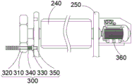
referring to fig. 1 to 7, the invention provides a squeegee assembly for a printer, comprising: the printing mechanism 100 comprises a containing pool for containing printing ink, an oil dipping roller arranged on the containing pool for dipping the printing ink, a printing roller contacted with the oil dipping roller and a printing bearing roller contacted with the printing roller, the printing mechanism 100 is a conventional structure, the bottom of the oil dipping roller is soaked below the liquid level of the printing ink in the containing pool, so that the printing ink can be transited to the printing roller through the oil dipping roller, a printing stock passes through the printing roller and the printing bearing roller, after the excessive printing ink on the printing roller is scraped by the doctor blade 210, the remained printing ink pattern is printed on the passing printing stock to finish printing, the steps are repeated, wherein the scraping of the printing ink by the doctor blade 210 directly influences the printing quality, the scraping force and the angle of the doctor blade 210 and the printing roller are required to be continuously adjusted to be optimal, and the subsequent printing quality is improved.
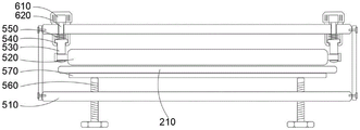
Referring to fig. 1, the doctor mechanism 200 includes a doctor blade 210 connected to a printing roller in a contact manner, a blade holder 220 for mounting and positioning the doctor blade 210, a mounting base 230 for providing a mounting position for the blade holder 220, a roller frame 240 for supporting the mounting base 230, a supporting frame 250 for supporting and erecting the roller frame 240, a clamping base 260 mounted at the bottom of the supporting frame 250, a sliding rail base 270 for providing a moving base for the clamping base 260, and a hydraulic press 280 for connecting and driving the clamping base 260 to move on the sliding rail base 270, wherein the doctor blade 210 is replaced by more than two groups through the doctor mechanism 200, and the position of the doctor blade 210 to be replaced is not required to be replaced after replacement, and the machine does not need to be stopped to wait for the removal of the doctor blade 210, and has less influence on the operation of the printing operation compared with the existing replacement method, which is beneficial to improving the printing efficiency, specifically, the blade holder 220 is used for clamping and fixing the doctor blade 210, the fixing position of the doctor blade 210 is convenient to replace and adjust, the mounting seat 230 and the tool rest 220 are of an assembled structure, the doctor blade 210 is convenient to replace after being disassembled, the roller frame 240 is of a roller frame structure, one side for mounting the mounting seat 230 is planar, the mounting seat 230 is convenient to mount, the mounting is convenient to mount and dismount by adopting bolt connection from inside to outside, at least two groups of tool rests 220 are arranged, the tool rests 220 are uniformly arranged on the roller frame 240 in a surrounding manner, at least two groups of the doctor blade 210 and a matched structure of the doctor blade 210 are arranged, the two groups of the doctor blade 210 can be normally replaced, the replacement period can be reduced by more groups, the large-scale production and use are convenient, the clamping seat 260 can be driven by the hydraulic press 280 to move on the slide rail seat 270, when the doctor blade 210 is replaced, the hydraulic press 280 drives the doctor mechanism 200 to move outwards, then the roller frame 240 is driven by the positioning mechanism 300 to rotate, the position of the doctor blade 210 is replaced, the position of the doctor blade 210 is moved out first, the blockage caused by the rotation of the printing roller to the doctor blade 210, the new doctor blade 210 is moved to the working position to contact the printing roller by pushing the hydraulic press 280 to reset, the doctor blade 210 is replaced, and then the doctor blade 210 which is moved out in a rotating mode is replaced as next standby replacement, so that the doctor blade 210 does not need to be stopped for waiting when being dismounted and mounted, and the printing efficiency of the device is improved.
Specifically, the mounting base 230 is provided with a groove seat for placing the tool holder 220, and the tool holder 220 can be stably clamped in the groove seat by matching with the fixing plug 430 for assembly and disassembly, the fixing plug 430 is inserted into the side surface of the groove seat, and the tool holder 220 inside the tool holder is fixed by penetrating through the side surface of the mounting base 230, so that the front and rear positioning of the tool holder assembly and disassembly are facilitated, and the feasibility of the device is improved.
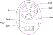
Referring to fig. 2, the positioning mechanism 300 includes a turntable 310 connected to one end of the roller frame 240, a limiting rod 320 inserted into the turntable 310 for positioning the roller frame 240, a limiting plate 330 installed on the limiting rod 320 for limiting, a first spring 340 connected to the limiting plate 330 and located outside the limiting rod 320, and a limiting hole 350 opened in the support frame 250 for inserting the limiting rod 320, the positioning mechanism 300 is mainly used for driving the roller frame 240 to rotate, and the doctor blade 210 can be replaced after the roller frame 240 is driven to rotate, so as to complete replacement of the doctor blade 210, and manual tool changing, automatic tool changing, or a combination of both can be realized, specifically, the turntable 310 can realize positioning of the roller frame 240 before and after rotation by being inserted into the limiting hole 350, first pull the limiting rod 320 outward to separate from the support frame 250, and then drive the roller frame 240 to rotate by rotating the turntable 310, the positioning mechanism 300 further includes a motor 360 coupled to the other end of the roller frame 240 for mechanically driving the roller frame 240 to rotate, certainly, when the force is insufficient, the roller frame 240 can be driven by the motor 360 in an auxiliary way, or can be driven by the motor 360 directly and completely, the two are used in a matching way, the operation and control effect is better, after the rotation is finished, the rotating disc 310 rotates for fine adjustment, and after the doctor blade 210 enters and exits the printing roller, the limiting rod 320 is moved to the outside of the corresponding limiting hole 350, the limiting rod 320 is pushed into the limiting hole 350 under the action of the first spring 340 to complete positioning, the stability of the ink scraping knife 210 in the ink scraping process is ensured, the anti-skidding handle is arranged at the outer side end of the limiting rod 320, the use by an operator is facilitated, the first spring 340 is positioned between the limiting rod 320 and the limiting plate 330, so that the first spring 340 can be conveniently inserted and positioned, and the rationality of the device is improved.
Further, spacing hole 350 has been seted up and has evenly encircled the multiunit on support frame 250, and the outside end of gag lever post 320 is equipped with anti-skidding handle, through encircleing the spacing hole 350 of multiunit that sets up, can drive gag lever post 320 to carousel 310 and fix a position in the settlement position, for example set up spacing hole 350 when scraping blade 210 contacts the printing roller, be convenient for peg graft and fix, the more quantity in spacing hole 350 of group number of scraping blade 210 is more, make the location more convenient accurate.
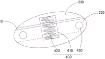
Referring to fig. 4, the hanging mechanism 400 includes a storage groove 410 correspondingly opened in the blade holder 220 and the mounting seat 230, a second spring 420 connected to the storage groove 410 for hanging, and a fixing plug 430 inserted into the blade holder 220 and the mounting seat 230 for fixing, the blade holder 220 and the mounting seat 230 can be separated by the hanging mechanism 400 when the doctor blade 210 is replaced, the blade holder 220 is hung by the second spring 420, the doctor blade 210 is replaced, the influence of mechanical vibration generated during replacement on the operating doctor blade 210 is effectively reduced by using the buffering of the second spring 420, and after replacement, the doctor blade is conveniently assembled by the fixing plug 430, specifically, the storage groove 410 can be set to be a plurality of hole-shaped structures or a long groove-shaped structure for uniformly arranging the plurality of second springs 420, two ends of the second spring 420 are respectively connected to the blade holder 220 and the mounting seat 230, the fixing plug 430 can be inserted into the blade holder 220 from the side of the mounting seat 230, the knife rest 220 is fixed on the mounting seat 230, the second spring 420 is stored in the storage groove 410, the doctor blade 210 is replaced, the fixing plug 430 is taken out firstly, then the knife rest 220 is separated from the mounting seat 230, the second spring 420 is used for hanging up, then the doctor blade 210 on the knife rest 220 is disassembled, assembled and replaced, the vibration generated in the disassembling and assembling process is weakened through the second spring 420, the vibration deviation of the doctor blade 210 influencing the current operation is avoided, the doctor effect is influenced, the knife rest 220 does not need to be completely removed, only the knife rest 220 needs to be lifted upwards during installation, the second spring 420 enters the mounting seat 230 again under the elastic force contraction of the second spring 420, the alignment is convenient, the installation is also simple and convenient, the second spring 420 adopts a contraction type spring, the second spring contracts at the back of the storage groove 410 under the normal state, the knife rest 220 is lengthened after the gravity of the knife rest 220, of course, the second spring 420 also can adopt a line type connecting structure with the buffer effect, the tool holder 220 only needs to be hung after being separated from the mounting seat 230, and the stability of the roller frame 240 is not influenced by the operation of the tool holder 220, so that the rationality and the feasibility of the device are improved.
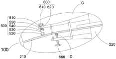
As shown in fig. 5-6, the adjusting mechanism 500 includes an extension frame 510 mounted on the blade frame 220, a positioning wheel 520 disposed on the extension frame 510 for pressing and limiting the doctor blade 210, a wheel frame 530 for fixing the positioning wheel 520, a positioning cylinder 540 movably engaged with the wheel frame 530, a spring 550 disposed in the positioning cylinder 540 for buffering, an adjusting bolt 560 screwed to the extension frame 510 and located below the doctor blade 210, and a connector 570 movably connected to the adjusting bolt 560 for supporting and fixing the doctor blade 210, and the angle of the doctor blade 210 at the doctor end can be adjusted by the adjusting mechanism 500 to change the angle between the doctor blade 210 and the printing roller, so as to achieve better doctor effect, compared with the prior art in which the angle of the doctor blade 210 is adjusted by the blade frame 220, the adjusting mechanism is more accurate at the front end, and has a buffering and protecting effect on the doctor blade 210, and the damage of the doctor blade 210 can be reduced by the spring 550 after external force is applied to the doctor blade 210, the ink scraping blade 210 is protected, the force of the ink scraping blade 210 contacting the printing roller can be adjusted in a self-adaptive mode, the positioning wheel 520 and the adjusting bolt 560 are arranged in a staggered mode, the positioning wheel 520 is close to the ink scraping end of the ink scraping blade 210, specifically, the positioning wheel 520 is pressed on the upper portion of the front end of the ink scraping blade 210, the connector 570 is pressed on the lower portion of the ink scraping blade 210 and is located behind the positioning wheel 520, when the adjusting bolt 560 is screwed down to drive the connector 570 to be pressed towards the ink scraping blade 210, the ink scraping blade 210 can be pressed, due to the elastic effect of the ink scraping blade 210, the front end of the ink scraping blade 210 can incline downwards, the angle of the ink scraping blade 210 can be adjusted according to the mode, the ink scraping blade 210 can be better contacted with the printing roller, the ink scraping effect is better, the ink scraping effect is more convenient to adjust, the spring 550 connected to the inner side of the wheel frame 530 can be used for driving the positioning wheel 520 to be tightly pressed in a self-adaptive mode, corresponding adaptation can be made along with the change of the stress of the ink scraping blade 210, the locating effect is better, and the outside of locating wheel 520 is equipped with the rubber slipmat, it is better to the fixed effect of ink scraping sword 210, the locating wheel 520 of the form that adopts the gyro wheel can make corresponding rotation when ink scraping sword 210 atress motion, the locating effect is better, and can upwards give a contact force of ink scraping sword 210 when the printing roller rotates, so that ink scraping sword 210 scrapes unnecessary ink, utilize spring 550 to keep the equilibrium of atress, for standard atress value under the operating condition, and adjusting bolt 560 and connector 570 adopt the connected mode of built-in movable head, make adjusting bolt 560 promote connector 570 top to ink scraping sword 210 when the fastening, extrude deformation with ink scraping sword 210, change the angle of its tip and printing roller, thereby the interior sleeve pipe has installed the rationality.
Referring to fig. 3 and 5, the monitoring mechanism 600 includes a pressure sensor 610 mounted on the extension frame 510, a pressure-applied push rod 620 passing through the extension frame 510 and connected to the wheel frame 530, a display screen 630 mounted on the support frame 250 and electrically connected to the pressure sensor 610, and an alarm 640 mounted on the side of the display screen 630 for warning, the monitoring mechanism 600 can utilize the connected adjusting mechanism 500 to monitor the stress condition of the doctor blade 210, adjust the stress condition according to the standard stress value, and gradually adjust the pressure detected by the pressure-applied push rod 620 to a standard pressure value when the positioning wheel 520 presses the doctor blade 210, the pressure data is obtained by the pressure-applied push rod 620 pressing the pressure sensor 610, and then the pressure data is sent to the electrically connected display screen 630 for displaying for manual viewing, when the stress value gradually decreases, it indicates that the doctor blade 210 is gradually worn, the contact dynamics between ink scraping blade 210 and the printing roller reduces, the wiping effect also reduces, reduce the setting value when contact pressure and send the police dispatch newspaper through siren 640 after, remind in time to change ink scraping blade 210, early warning monitoring has been realized, compare and judge through observing the printing achievement, the continuity of printing has been guaranteed, the waste that the printing is bad to lead to has been avoided, of course, also can set up pressure sensor 610 in the inside of a location section of thick bamboo 540, the pressure data is reachd through the pressure degree that receives that detects spring 550, must not inseparable with the printing roller contact after ink scraping blade 210's the tip wearing and tearing. Therefore, the stress of the positioning wheel 520 is reduced, the spring 550 is properly prolonged, the stress is smaller than the standard stress value, the detection mode is accurate and reasonable, the actual reference meaning is realized, and the popularization and the use are convenient.
Example two:
with reference to fig. 5-6, on the basis of the first embodiment, the ball 571 is engaged with the inner side of the connector 570, the other side of the ball 571 abuts against the adjusting bolt 560, and the sliding friction is changed into the rolling friction by the ball 571, so that the adjusting bolt 560 can rotate more conveniently, the state of the connector 570 is not affected, the connector 570 is prevented from being forced to deviate, and the adjustment is simpler and more convenient, thereby improving the rationality and feasibility of the device.
Example three:
referring to fig. 7, in the above embodiment, at least two sets of pressure sensors 610, adjusting bolts 560 and wheel frames 530 are provided, and are used for adjusting the doctor blade 210 in a balanced manner, because the doctor blade 210 is of a plate structure, at least two sets of mechanisms need to be provided on the doctor blade 210, for example, the two or more sets of adjusting bolts 560 can make the connector 570 stably and neatly extrude the doctor blade 210 upward, so that the doctor blade 210 has a better adjusting effect, the two sets of pressure sensors 610 can respectively perform pressure adjustment on two sides of the doctor blade 210, thereby ensuring the balance of deformation of two sides of the doctor blade 210, facilitating control and adjustment, making the adjusted doctor blade 210 more accurate, and the doctor blade effect is better, thereby improving the feasibility of the device.
The working principle and the using process of the invention are as follows: firstly, the ink scraping mechanism 200 is arranged on the side of the printing mechanism 100, the ink scraping blade 210 is driven to contact a printing roller through the hydraulic press 280, then the adjusting bolt 560 is rotated, the ink scraping blade 210 is pressed through the adjusting bolt 560 to deform the ink scraping blade 210, the angle between the ink scraping end of the ink scraping blade 210 and the printing roller is adjusted, at this time, the ink scraping blade 210 presses the spring 550 after being pressed, the pressing push rod 620 is pushed to push the pressure sensor 610, pressure data is obtained through the pressure sensor 610, then the pressure data is displayed from the display screen 630 until a preset value is reached, at this time, the ink scraping blade 210 and the printing roller are in a qualified ink scraping standard, the adjustment of the ink scraping blade 210 is completed, during operation, the ink scraping blade 210 scrapes off redundant ink on the printing roller, a printing stock is printed between the printing roller and a printing roller, abrasion is generated along with the increase of the service time of the ink scraping blade 210, so that the contact force between the ink scraping blade 210 and the printing roller is reduced, the ink scraping effect is reduced, so that the stress of the ink scraping blade 210 is reduced, the spring 550 is self-adaptively extended, the pressure detected by the pressure sensor 610 is reduced, when the detected pressure value is reduced to a preset value, an alarm is given through the alarm 640 to remind an operator of timely replacement, the hydraulic press 280 drives the ink scraping blade 210 to move outwards during replacement, the limiting rod 320 is pulled outwards to separate the limiting rod 320 from the limiting hole 350, then the rotary table 310 drives the roller frame 240 to rotate, the motor 360 assists the rotation of the roller frame 240 to rotate a new ink scraping blade 210 to the ink scraping position, the limiting rod 320 is loosened, the limiting rod 320 is driven to be inserted into the limiting hole 350 under the action of the spring one 340, the ink scraping blade 210 is driven to be close to a printing roller through the hydraulic press 280 to complete the positioning of the ink scraping blade 210, the angle of the ink scraping end of the ink scraping blade 210 and the contact force of the ink scraping blade 210 and the printing roller are adjusted through the rotation adjusting bolt 560, continuing the operation, when changing the doctor blade 210, taking out the fixed plug 430 first, at this moment, the knife rest 220 breaks away from in the mount pad 230 under the effect of gravity, utilize second spring 420 to hang up, then change the doctor blade 210 on knife rest 220, the vibrations that produce are weakened through second spring 420, after changing and finishing, lift up knife rest 220, draw knife rest 220 into the inside of mount pad 230 with the assistance of second spring 420, peg graft fixed plug 430, finish fixing, reserve, can.
In the present invention, the term "plurality" means two or more unless explicitly defined otherwise. As used herein, the term "and/or" includes any and all combinations of one or more of the associated listed items. The terms "mounted," "connected," "fixed," and the like are to be construed broadly, and for example, "connected" may be a fixed connection, a removable connection, or an integral connection; "coupled" may be direct or indirect through an intermediary. The specific meanings of the above terms in the present invention can be understood by those skilled in the art according to specific situations.
It will be understood that when an element is referred to as being "mounted to," "secured to" or "disposed on" another element, it can be directly on the other element or intervening elements may also be present. When an element is referred to as being "connected" to another element, it can be directly connected to the other element or intervening elements may also be present. The terms "vertical," "horizontal," "upper," "lower," "left," "right," and the like as used herein are for illustrative purposes only and do not denote a unique embodiment.
In the description herein, the description of the terms "one embodiment," "some embodiments," "specific embodiments," etc., means that a particular feature, structure, material, or characteristic described in connection with the embodiment or example is included in at least one embodiment or example of the invention. In this specification, the schematic representations of the terms used above do not necessarily refer to the same embodiment or example. Furthermore, the particular features, structures, materials, or characteristics described may be combined in any suitable manner in any one or more embodiments or examples.
Although embodiments of the present invention have been shown and described, it will be appreciated by those skilled in the art that changes, modifications, substitutions and alterations can be made in these embodiments without departing from the principles and spirit of the invention, the scope of which is defined in the claims and their equivalents.