CN113199789A - Solid-liquid separation briquetting machine based on paint slag - Google Patents
Solid-liquid separation briquetting machine based on paint slag Download PDFInfo
- Publication number
- CN113199789A CN113199789A CN202110327386.7A CN202110327386A CN113199789A CN 113199789 A CN113199789 A CN 113199789A CN 202110327386 A CN202110327386 A CN 202110327386A CN 113199789 A CN113199789 A CN 113199789A
- Authority
- CN
- China
- Prior art keywords
- solid
- liquid separation
- liquid
- briquetting machine
- paint
- Prior art date
- Legal status (The legal status is an assumption and is not a legal conclusion. Google has not performed a legal analysis and makes no representation as to the accuracy of the status listed.)
- Pending
Links
Images


Classifications
-
- B—PERFORMING OPERATIONS; TRANSPORTING
- B30—PRESSES
- B30B—PRESSES IN GENERAL
- B30B9/00—Presses specially adapted for particular purposes
- B30B9/02—Presses specially adapted for particular purposes for squeezing-out liquid from liquid-containing material, e.g. juice from fruits, oil from oil-containing material
- B30B9/04—Presses specially adapted for particular purposes for squeezing-out liquid from liquid-containing material, e.g. juice from fruits, oil from oil-containing material using press rams
- B30B9/06—Presses specially adapted for particular purposes for squeezing-out liquid from liquid-containing material, e.g. juice from fruits, oil from oil-containing material using press rams co-operating with permeable casings or strainers
-
- B—PERFORMING OPERATIONS; TRANSPORTING
- B09—DISPOSAL OF SOLID WASTE; RECLAMATION OF CONTAMINATED SOIL
- B09B—DISPOSAL OF SOLID WASTE
- B09B3/00—Destroying solid waste or transforming solid waste into something useful or harmless
-
- B—PERFORMING OPERATIONS; TRANSPORTING
- B30—PRESSES
- B30B—PRESSES IN GENERAL
- B30B15/00—Details of, or accessories for, presses; Auxiliary measures in connection with pressing
- B30B15/0005—Details of, or accessories for, presses; Auxiliary measures in connection with pressing for briquetting presses
-
- B—PERFORMING OPERATIONS; TRANSPORTING
- B30—PRESSES
- B30B—PRESSES IN GENERAL
- B30B15/00—Details of, or accessories for, presses; Auxiliary measures in connection with pressing
- B30B15/30—Feeding material to presses
-
- B—PERFORMING OPERATIONS; TRANSPORTING
- B30—PRESSES
- B30B—PRESSES IN GENERAL
- B30B15/00—Details of, or accessories for, presses; Auxiliary measures in connection with pressing
- B30B15/32—Discharging presses
Abstract
The invention relates to the technical field of solid-liquid separation, and discloses a solid-liquid separation briquetting machine based on paint residues, which comprises: the device comprises a rack, a receiving hopper arranged at the upper end of the rack and a storage bin arranged at the bottom of the receiving hopper; it is characterized by also comprising: the extruding device is arranged on the rack, a solid-liquid separation compression sleeve for placing paint residues is arranged in the extruding device, and the extruding device is used for separating the paint residues from liquid so as to extrude the paint residues into massive solids; in the process of separating the paint residues from the liquid, the invention simultaneously recovers the massive solid and the liquid, saves resources, and adopts a physical compression method, so that new chemical pollution can not be generated in the compression process.
Description
Technical Field
The invention relates to the technical field of solid-liquid separation, in particular to a solid-liquid separation briquetting machine based on paint residues.
Background
At present, the conventional cloth bag filling and precipitating mode is adopted, and the liquid in the paint slag generated after the water curtain is sprayed paint is precipitated and separated, so that the following problems can be generated:
firstly, the precipitation separation efficiency is low, and the time is long;
secondly, the residual water amount in the paint slag after precipitation is high, and the effect is general;
thirdly, the separated water is not easy to recover, the durability of the cloth bag is not high, and the separation effect is influenced;
fourthly, the solid-liquid separation work of the paint residues can not be automatically carried out, and the manpower is wasted.
Disclosure of Invention
The application provides a solid-liquid separation briquetting machine based on paint sediment to solve paint sediment solid-liquid separation thoroughly, separation efficiency is low, and the paint sediment and the difficult recovery of water after the separation, separator easily abrade and waste technical problem such as manpower.
In order to solve the technical problem, the application provides a solid-liquid separation briquetting machine based on paint sediment includes: the compression device comprises a rack, a compression main body, a receiving hopper arranged at the upper end of the rack and a storage bin arranged at the bottom of the receiving hopper; it is characterized by also comprising: the extrusion device is arranged on the rack, a solid-liquid separation compression sleeve used for placing paint residues is arranged in the extrusion device, and the extrusion device is used for separating the paint residues from liquid so as to extrude the paint residues into blocky solids.
In some embodiments of the present application, the solid-liquid separation briquetting machine further includes: the pan feeding device set up in extrusion device's entry end, just the cylinder body of pan feeding device drives the paint sediment is followed the one end of feed bin to extrusion device moves, and will the paint sediment propelling movement extremely in the solid-liquid separation compression sleeve.
In some embodiments of the present application, the solid-liquid separation briquetting machine further includes: prevent built on stilts subassembly, set up in on the feed bin, prevent built on stilts subassembly and be used for the stirring paint sediment to subduct the gap between the paint sediment.
In some embodiments of the present application, the solid-liquid separation briquetting machine further includes: and the block discharging device is arranged at the bottom of the extruding device and is used for discharging the blocky solid to the blocky solid collecting device from the extruding device.
In some embodiments of the present application, the block arranging means comprises: the door blocking plate is arranged at the bottom of the extrusion device; the horizontal hydraulic cylinder is connected with the door stop plate and reciprocates at the bottom of the extrusion device along the horizontal direction so as to drive the door stop plate to be opened and closed; and the block arranging guide groove is arranged at the outlet end of the extruding device and is used for guiding the blocky solid to move to the blocky solid collecting device along the block arranging guide groove.
Some of this application are embodiments, the solid-liquid separation briquetting machine further includes: the liquid guide groove is arranged at the bottom of the solid-liquid separation compression sleeve; the water collecting tank is arranged on one side of the rack and is connected with the liquid guide groove; the liquid level gauge is arranged on the rack and used for detecting the liquid level in the water collecting tank; and the liquid discharge pump is arranged at the upper end of the water collecting tank and is used for pumping liquid in the water collecting tank to the on-site liquid tank.
In some embodiments of the present application, the solid-liquid separation briquetting machine further includes: the lower hydraulic system is arranged on the lower side of the rack and connected with the extrusion device and the horizontal hydraulic cylinder, and the lower hydraulic system is used for providing power for the extrusion device and the horizontal hydraulic cylinder.
In some embodiments of the present application, the pressing device comprises: the vertical hydraulic cylinder is fixed at the upper end of the rack; and the extrusion assembly is connected to the vertical hydraulic cylinder, the power of the extrusion assembly is provided by the vertical hydraulic cylinder, and the extrusion assembly reciprocates along the vertical direction.
In some embodiments of the present application, the compression assembly comprises: the compression ejector rod is arranged at the front end of the cylinder rod of the vertical hydraulic cylinder and reciprocates in the vertical direction in an inner cavity of a solid-liquid separation compression sleeve in a compression main body connected with the vertical hydraulic cylinder; and the compression top head is connected to one end of the compression top rod and is in contact with the paint residues.
In some embodiments of the present application, the solid-liquid separation briquetting machine further comprises: the truckles are arranged at the bottom of the underlying hydraulic system, and the number of the truckles is set to be a plurality.
The invention provides a solid-liquid separation briquetting machine based on paint residues, which comprises: the device comprises a rack, a receiving hopper arranged at the upper end of the rack and a storage bin arranged at the bottom of the receiving hopper; further comprising: the extruding device is arranged on the rack, a solid-liquid separation compression sleeve for placing paint residues is arranged in the extruding device, and the extruding device is used for separating the paint residues from liquid so as to extrude the paint residues into massive solids; in the process of separating the paint residues from the liquid, the invention simultaneously recovers the massive solid and the liquid, saves resources, adopts a physical compression method, shortens the solid-liquid separation time, does not generate new chemical pollution in the compression process, can improve the automation degree of the solid-liquid separation of the paint residues, and saves manpower.
Drawings
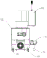
FIG. 1 is a front view of an embodiment of the present invention;
FIG. 2 is a right side sectional view of an embodiment of the present invention;
FIG. 3 is a left side sectional view of an embodiment of the present invention;
FIG. 4 is a front view of the extrusion apparatus of the present invention;
fig. 5 is a front view of the block arraying device of the present invention.
In the figure, 100, a rack; 110. an electric control cabinet; 120. a water collection tank; 130. a liquid level gauge; 140. a liquid discharge pump; 150. a hydraulic system is arranged below; 160. a caster wheel;
200. a receiving hopper;
300. a storage bin; 310. an anti-overhead assembly;
400. an extrusion device; 410. a vertical hydraulic cylinder; 420. an extrusion assembly; 421. compressing the ejector rod; 422. compressing the plug; 430. a solid-liquid separation compression sleeve;
500. a feeding device;
600. a block arranging device; 610. a door stopper plate; 620. a horizontal hydraulic cylinder; 630. and a row of block guide grooves.
Detailed Description
The following detailed description of embodiments of the present invention is provided in connection with the accompanying drawings and examples. The following examples are intended to illustrate the invention but are not intended to limit the scope of the invention.
In the description of the present application, it is to be understood that the terms "center", "upper", "lower", "front", "rear", "left", "right", "vertical", "horizontal", "top", "bottom", "inner", "outer", and the like indicate orientations or positional relationships based on those shown in the drawings, and are only for convenience in describing the present application and simplifying the description, but do not indicate or imply that the referred device or element must have a particular orientation, be constructed in a particular orientation, and be operated, and thus should not be construed as limiting the present application.
The terms "first", "second" and "first" are used for descriptive purposes only and are not to be construed as indicating or implying relative importance or implicitly indicating the number of technical features indicated. Thus, a feature defined as "first" or "second" may explicitly or implicitly include one or more of that feature. In the description of the present application, "a plurality" means two or more unless otherwise specified.
In the description of the present application, it is to be noted that, unless otherwise explicitly specified or limited, the terms "mounted," "connected," and "connected" are to be construed broadly, e.g., as meaning either a fixed connection, a removable connection, or an integral connection; can be mechanically or electrically connected; they may be connected directly or indirectly through intervening media, or they may be interconnected between two elements. The specific meaning of the above terms in the present application can be understood in a specific case by those of ordinary skill in the art.
As shown in fig. 1, in some embodiments according to the present application, a paint slag-based solid-liquid separation briquetting machine includes: the device comprises a rack 100, a receiving hopper 200 arranged at the upper end of the rack 100 and a storage bin 300 arranged at the bottom of the receiving hopper 200; further comprising: the extrusion device 400 is arranged on the rack 100, a solid-liquid separation compression sleeve 430 for placing paint residues is arranged in the extrusion device 400, and the extrusion device 400 is used for separating the paint residues from liquid so as to extrude the paint residues into massive solids.
It should be noted that the receiving hopper 200 is connected to a deslagging system in a production line, the receiving hopper 200 and the deslagging system can be connected by signals, when the receiving hopper 200 receives a deslagging signal from the deslagging system, a material port of the receiving hopper 200 is opened, and paint slag enters the receiving hopper 200 from the deslagging system and then enters the bin 300 on the lower side of the receiving hopper 200.
As shown in fig. 2, in some embodiments according to the present application, the solid-liquid separation briquetting machine further includes: the feeding device 500 is arranged at the inlet end of the extruding device 400, and the cylinder body of the feeding device 500 drives the paint slag to move towards the extruding device 400 along one end of the storage bin 300, and pushes the paint slag into the solid-liquid separation compression sleeve 430.
It should be noted here that the feeding device 500 is an electric pushing cylinder, a motor of the feeding device 500 is electrically connected to an electric control system in the electric control cabinet 110, the electric control system in the electric control cabinet 110 controls a pushing rod of the feeding device 500 to reciprocate in the cylinder to fill the solid-liquid separation compression sleeve 430 with paint slag, and the feeding device 500 is connected to a speed reducer which provides power for the feeding device 500.
As shown in fig. 5, in some embodiments according to the present application, the solid-liquid separation briquetting machine further includes: the overhead prevention assembly 310 is arranged on the bin 300, and the overhead prevention assembly 310 is used for stirring the paint residues so as to reduce gaps among the paint residues.
It should be noted here that the rotating motor of the overhead component 310 is connected to the electric control system in the electric control cabinet 110, and when the paint slag enters the storage bin 300, the electric control system in the electric control cabinet 110 controls the rotating motor to drive the stirring arm of the overhead component 310 to stir the paint slag, so that gaps between the paint slag are reduced, the feeding efficiency is improved, and the paint slag in the solid-liquid separation compression sleeve 430 is guaranteed to be dense enough and can be extruded into blocks.
As shown in fig. 5, in some embodiments according to the present application, the solid-liquid separation briquetting machine further includes: and the block discharging device 600 is arranged at the bottom of the extruding device 400, and the block discharging device 600 is used for discharging the block solid out of the extruding device 400 to the block solid collecting device.
In some embodiments according to the present application, the block arraying apparatus 600 comprises: a shutter plate 610 disposed at the bottom of the extrusion apparatus 400; the horizontal hydraulic cylinder 620 is connected to the door stop plate 610, and the horizontal hydraulic cylinder 620 reciprocates at the bottom of the extrusion device 400 along the horizontal direction to drive the door stop plate 610 to open and close; and a block discharging guide groove 630 disposed at an outlet end of the extrusion apparatus 400, wherein the block discharging guide groove 630 is used for guiding the block solids to move to the block solids collecting apparatus along the block discharging guide groove 630.
It should be noted here that, in the process of extruding the paint slag, the door stopper 610 is in a closed state, when the paint slag in the extruding device 400 reaches a set pressure value, it is determined that the solid-liquid separation work is completed, the horizontal hydraulic cylinder 620 drives the door stopper 610 to open, the compression top 422 pushes out the pressed paint slag blocks and discharges the paint slag blocks to a collection device designated by a customer through the horizontal block discharge guide slot 630, wherein the power of the horizontal hydraulic cylinder 620 is provided by the lower hydraulic system 150, the pump body and the electromagnetic valve connected with the horizontal hydraulic cylinder 620 are electrically connected to the electric control system in the electric control cabinet 110, and the electric control system in the electric control cabinet 110 controls the working process of the horizontal hydraulic cylinder 620.
According to some embodiments of the present application, the solid-liquid separation briquetting machine further comprises: the liquid guide groove is arranged at the bottom of the solid-liquid separation compression sleeve 430; a water collection tank 120 disposed at one side of the frame 100, and the water collection tank 120 is connected to the liquid guide groove; a liquid level gauge 130 disposed on the frame 100, the liquid level gauge 130 being used to detect a liquid level in the water collection tank 120; and a drain pump 140 disposed at an upper end of the header tank 120, the drain pump 140 being for pumping the liquid in the header tank 120 to the on-site tank.
It should be noted that the bottom of the squeezing device 400 is a slit structure, the vertical hydraulic cylinder 410 presses the paint residues into the slit structure, the slit structure isolates the paint residues, the liquid in the paint residues is separated out through the slit structure and enters the water collecting tank 120 through the liquid guiding groove, and when the liquid level gauge 130 detects that the water level in the water collecting tank 120 is too high, the liquid drainage pump 140 is started to convey the liquid in the water collecting tank 120 to the on-site liquid tank.
According to some embodiments of the present application, the underneath hydraulic system 150 is disposed at the lower side of the frame 100, and the underneath hydraulic system 150 is connected to the press device 400 and the horizontal hydraulic cylinder 620, and the underneath hydraulic system 150 is used for providing power for the movement of the vertical hydraulic cylinder 410 in the press device 400 and the horizontal hydraulic cylinder 620 in the block arranging device 600.
In some embodiments according to the present application, the pressing device 400 comprises: a vertical hydraulic cylinder 410 fixed to the upper end of the frame 100; and a compressing assembly 420 connected to the vertical hydraulic cylinder 410, wherein power of the compressing assembly 420 is supplied by the vertical hydraulic cylinder 410, and the compressing assembly 420 reciprocates in a vertical direction.
As shown in fig. 4, in some embodiments according to the present application, the compression assembly 420 includes: the compression ejector rod 421 is arranged in the inner cavity of the vertical hydraulic cylinder 410 and connected to the front end of the cylinder rod of the vertical hydraulic cylinder 410, and the compression ejector rod 421 reciprocates in the inner cavity of the solid-liquid separation compression sleeve in the compression main body connected with the vertical hydraulic cylinder 410 along the vertical direction; and a compression head 422 connected to one end of the compression top bar 421, wherein the compression head 422 contacts the paint residue.
It should be noted here that the underneath hydraulic system 150 provides power for the reciprocating motion of the vertical hydraulic cylinder 410 in the vertical direction, the electromagnetic valve and the pump body connected with the vertical hydraulic cylinder 410 are connected to the electric control system in the electric control cabinet 110, the electric control system in the electric control cabinet 110 controls the vertical hydraulic cylinder 410 to work, when the paint slag is filled into the solid-liquid separation compression sleeve 430, the vertical hydraulic cylinder 410 drives the vertical push rod to move in the direction of the solid-liquid separation compression sleeve 430, the compression push head 422 connected to the compression push rod 421 applies pressure to the solid-liquid separation compression sleeve 430 and the paint slag inside the solid-liquid separation compression sleeve 430, the paint slag is pressed into the slit structure, the solid-liquid separation is completed, and the paint slag is pressed into blocks.
As shown in fig. 3, in some embodiments according to the present application, the solid-liquid separation briquetting machine further includes: the caster 160 is disposed at the bottom of the underlying hydraulic system 150, and the number of the caster 160 is plural.
It should be noted here that truckle 160 makes the whole removal that can realize of equipment, convenient transportation, but when the solid-liquid separation briquetting machine during operation, truckle 160 probably becomes the risk factor, truckle 160 has the telescopic function, when needs remove the solid-liquid separation briquetting machine, manual with the locating piece rise, can pushing equipment, when the solid-liquid separation briquetting machine carries out the briquetting operation, the locating piece is manually fallen, make the locating piece contact ground, increase the frictional force on equipment and ground, make equipment more stable at the during operation.
The working process of the solid-liquid separation briquetting machine is as follows: the solid-liquid separation briquetting machine is arranged at a centralized slag discharge port at the tail end of the water curtain paint spraying production line, can be in signal connection with a slag discharge system of the production line or use a material level detection probe, realizes automatic starting of the solid-liquid separation briquetting machine when paint slag to be pressed exists, and realizes an unattended operation mode or manual feeding in which the material is automatically stopped after compression and separation are finished; paint slag to be pressed enters the receiving hopper 200 of the equipment, when the paint slag enters the storage bin 300 from the receiving hopper 200, the paint slag is stirred by the anti-overhead assembly 310 to reduce gaps among the paint slag, then the paint slag to be pressed is filled into the solid-liquid separation compression sleeve 430 arranged in the compression main body by the horizontally arranged feeding device 500, the compression ejector rod 421 and the compression ejector head 422 are pushed by the vertically arranged vertical hydraulic cylinder 410, the solid wastes such as the paint slag to be compressed are separated and compressed into blocks in the strip seam structure by using a physical compression method, the liquid separated in the compression separation process is separated out by the strip seam structure and is discharged to the water collecting tank 120 through the liquid guide tank, the liquid is controlled by the liquid discharge pump 140 and the liquid level device 130, when the liquid reaches a high liquid level, the liquid discharge pump 140 is started to return the collected compressed separated liquid to the liquid tank on the spot of a client, the liquid can be recycled, the liquid is separated and then pressed into the paint slag blocks, after the set pressure value is reached, the horizontal hydraulic cylinder 620 drives the door stop plate 610 to be opened, the compression top head 422 pushes out the pressed paint slag blocks and then discharges the paint slag blocks to a collection container appointed by a customer through the block arrangement guide groove 630, then the compression top rod 421 and the compression top head 422 move upwards along the vertical direction and return to a state to be compressed, and the horizontal hydraulic cylinder 620 drives the door stop plate 610 to be closed; after the paint slag in the bin 300 is pressed, the automatic operation of the equipment cannot detect a pressure signal, and the automatic operation stops.
To sum up, the invention relates to the technical field of solid-liquid separation, and discloses a solid-liquid separation briquetting machine based on paint slag, which comprises: the device comprises a rack, a receiving hopper arranged at the upper end of the rack and a storage bin arranged at the bottom of the receiving hopper; further comprising: the extruding device is arranged on the rack, a solid-liquid separation compression sleeve for placing paint residues is arranged in the extruding device, and the extruding device is used for separating the paint residues from liquid so as to extrude the paint residues into massive solids; in the process of separating the paint residues from the liquid, the invention simultaneously recovers the massive solid and the liquid, saves resources, and adopts a physical compression method, so that new chemical pollution can not be generated in the compression process.
The above description is only a preferred embodiment of the present invention, and it should be noted that, for those skilled in the art, various modifications and substitutions can be made without departing from the technical principle of the present invention, and these modifications and substitutions should also be regarded as the protection scope of the present invention.
Claims (10)
1. A solid-liquid separation briquetting machine based on paint slag comprises: the device comprises a rack, a receiving hopper arranged at the upper end of the rack and a storage bin arranged at the bottom of the receiving hopper;
it is characterized by also comprising:
the extrusion device is arranged on the rack, a solid-liquid separation compression sleeve used for placing paint residues is arranged in the extrusion device, and the extrusion device is used for extruding the paint residues into massive solids so as to separate the paint residues from liquid.
2. The solid-liquid separation briquetting machine of claim 1, further comprising:
the pan feeding device set up in extrusion device's entry end, just the cylinder body of pan feeding device drives the paint sediment is followed the one end of feed bin to extrusion device moves, and will the paint sediment propelling movement extremely in the solid-liquid separation compression sleeve.
3. The solid-liquid separation briquetting machine of claim 1, further comprising:
prevent built on stilts subassembly, set up in on the feed bin, prevent built on stilts subassembly and be used for the stirring paint sediment to subduct the gap between the paint sediment.
4. The solid-liquid separation briquetting machine of claim 1, further comprising:
and the block discharging device is arranged at the bottom of the extruding device and is used for discharging the blocky solid to the collecting device.
5. The solid-liquid separation briquetting machine of claim 4, wherein the briquette discharging device comprises:
the door blocking plate is arranged at the bottom of the extrusion device;
the horizontal hydraulic cylinder is connected with the door stop plate and reciprocates at the bottom of the extrusion device along the horizontal direction so as to drive the door stop plate to be opened and closed;
and the block arranging guide groove is arranged at the outlet end of the extruding device and guides the blocky solid to move to the collecting device along the block arranging guide groove.
6. The solid-liquid separation briquetting machine of claim 1, further comprising:
the liquid guide groove is arranged at the bottom of the solid-liquid separation compression sleeve;
the water collecting tank is arranged on one side of the rack and is connected with the liquid guide groove;
the liquid level gauge is arranged on the rack and used for detecting the liquid level in the water collecting tank;
and the liquid discharge pump is arranged at the upper end of the water collecting tank and is used for pumping liquid in the water collecting tank to the on-site liquid tank.
7. The solid-liquid separation briquetting machine of claim 5, further comprising:
the lower hydraulic system is arranged on the lower side of the rack and connected with the extrusion device and the horizontal hydraulic cylinder, and the lower hydraulic system is used for providing power for the extrusion device and the horizontal hydraulic cylinder.
8. The solid-liquid separation briquetting machine of any of claims 1 to 7, wherein the pressing device comprises:
the vertical hydraulic cylinder is fixed at the upper end of the rack;
and the extrusion assembly is connected to the vertical hydraulic cylinder, the power of the extrusion assembly is provided by the vertical hydraulic cylinder, and the extrusion assembly reciprocates along the vertical direction.
9. The solid-liquid separation briquetting machine of claim 8, wherein the pressing assembly includes:
the compression ejector rod is arranged at the front end of the cylinder rod of the vertical hydraulic cylinder and reciprocates in the vertical direction in an inner cavity of a solid-liquid separation compression sleeve in a compression main body connected with the vertical hydraulic cylinder;
and the compression top head is connected to one end of the compression top rod and is in contact with the paint residues.
10. The solid-liquid separation briquetting machine of claim 7, further comprising:
the truckles are arranged at the bottom of the underlying hydraulic system, and the number of the truckles is set to be a plurality.
Priority Applications (1)
| Application Number | Priority Date | Filing Date | Title |
|---|---|---|---|
| CN202110327386.7A CN113199789A (en) | 2021-03-26 | 2021-03-26 | Solid-liquid separation briquetting machine based on paint slag |
Applications Claiming Priority (1)
| Application Number | Priority Date | Filing Date | Title |
|---|---|---|---|
| CN202110327386.7A CN113199789A (en) | 2021-03-26 | 2021-03-26 | Solid-liquid separation briquetting machine based on paint slag |
Publications (1)
| Publication Number | Publication Date |
|---|---|
| CN113199789A true CN113199789A (en) | 2021-08-03 |
Family
ID=77025753
Family Applications (1)
| Application Number | Title | Priority Date | Filing Date |
|---|---|---|---|
| CN202110327386.7A Pending CN113199789A (en) | 2021-03-26 | 2021-03-26 | Solid-liquid separation briquetting machine based on paint slag |
Country Status (1)
| Country | Link |
|---|---|
| CN (1) | CN113199789A (en) |
Citations (9)
| Publication number | Priority date | Publication date | Assignee | Title |
|---|---|---|---|---|
| CN103817138A (en) * | 2014-03-07 | 2014-05-28 | 左伏根 | Method for resourceful treatment of paint residue waste |
| CN203699422U (en) * | 2013-12-13 | 2014-07-09 | 南京钢铁股份有限公司 | Dustless automatic ash discharging device |
| CN105196592A (en) * | 2015-09-21 | 2015-12-30 | 宁波福晨环保科技有限公司 | Hydraulic solid-liquid separator |
| CN105965946A (en) * | 2016-07-12 | 2016-09-28 | 南通建恒机械制造有限公司 | Full-automatic briquetting machine for aluminum foil leftovers |
| CN205774712U (en) * | 2016-06-27 | 2016-12-07 | 福建青拓镍业有限公司 | A kind of lateritic nickel ore pre-treatment production line wastewater sedimentation slag retracting device |
| CN106273625A (en) * | 2015-05-28 | 2017-01-04 | 沙玛科技股份有限公司 | Fragment compressor |
| CN108943805A (en) * | 2018-08-28 | 2018-12-07 | 湖南大三湘茶油股份有限公司 | Solid-liquid expression separation machine |
| CN208558384U (en) * | 2018-02-06 | 2019-03-01 | 成都宝钢制罐有限公司 | A kind of waste material automatic packaging system suitable for two-piece can production |
| CN112373094A (en) * | 2020-10-20 | 2021-02-19 | 廊坊市泽田依诺机械设备有限公司 | Solid-liquid separation compression sleeve |
-
2021
- 2021-03-26 CN CN202110327386.7A patent/CN113199789A/en active Pending
Patent Citations (9)
| Publication number | Priority date | Publication date | Assignee | Title |
|---|---|---|---|---|
| CN203699422U (en) * | 2013-12-13 | 2014-07-09 | 南京钢铁股份有限公司 | Dustless automatic ash discharging device |
| CN103817138A (en) * | 2014-03-07 | 2014-05-28 | 左伏根 | Method for resourceful treatment of paint residue waste |
| CN106273625A (en) * | 2015-05-28 | 2017-01-04 | 沙玛科技股份有限公司 | Fragment compressor |
| CN105196592A (en) * | 2015-09-21 | 2015-12-30 | 宁波福晨环保科技有限公司 | Hydraulic solid-liquid separator |
| CN205774712U (en) * | 2016-06-27 | 2016-12-07 | 福建青拓镍业有限公司 | A kind of lateritic nickel ore pre-treatment production line wastewater sedimentation slag retracting device |
| CN105965946A (en) * | 2016-07-12 | 2016-09-28 | 南通建恒机械制造有限公司 | Full-automatic briquetting machine for aluminum foil leftovers |
| CN208558384U (en) * | 2018-02-06 | 2019-03-01 | 成都宝钢制罐有限公司 | A kind of waste material automatic packaging system suitable for two-piece can production |
| CN108943805A (en) * | 2018-08-28 | 2018-12-07 | 湖南大三湘茶油股份有限公司 | Solid-liquid expression separation machine |
| CN112373094A (en) * | 2020-10-20 | 2021-02-19 | 廊坊市泽田依诺机械设备有限公司 | Solid-liquid separation compression sleeve |
Similar Documents
| Publication | Publication Date | Title |
|---|---|---|
| CN103129889B (en) | Horizontal quantitative prepressing type large-scale garbage compressor | |
| CN108891544B (en) | Intelligent water surface garbage recycling system based on unmanned ship | |
| CN113199789A (en) | Solid-liquid separation briquetting machine based on paint slag | |
| CN210792193U (en) | Aloe juice extraction element | |
| CN210057451U (en) | Extraction element of ferment stoste | |
| CN211999410U (en) | Oily sludge treatment device | |
| CN211713923U (en) | Automatic water surface garbage collecting and compressing device | |
| CN115302253B (en) | Precision machining grinding equipment for industrial connector | |
| CN211762800U (en) | Intelligent plastic bottle recovery device | |
| CN115215419B (en) | Lime neutralization system | |
| CN217757121U (en) | Multifunctional sewage treatment device | |
| CN114558831B (en) | Recycling treatment process for copper foil production waste | |
| CN113552299B (en) | Pesticide residue detection device for storing agricultural and sideline products and use method thereof | |
| CN216550059U (en) | Domestic sludge dewatering solidification equipment | |
| CN211643955U (en) | Dust collecting and compressing device | |
| CN110624296A (en) | High-efficient ore pulp dross removal mechanism | |
| CN115425319A (en) | Full-automatic crushing and sorting system for waste batteries | |
| CN211077236U (en) | Garbage truck case with sewage separation function | |
| CN211227840U (en) | Corrugated paper processing waste paper recycling device | |
| CN114563540A (en) | Vegetable food engineering pesticide residue detection device | |
| CN215918605U (en) | Clout recovery unit for accurate hardware products | |
| CN205767634U (en) | Net belt type slagging-off car | |
| CN219427561U (en) | Solid powder pressing forming machine | |
| CN220328150U (en) | Solid waste recycling equipment for sewage environmental protection | |
| CN219632186U (en) | Waste recycling and compressing device |
Legal Events
| Date | Code | Title | Description |
|---|---|---|---|
| PB01 | Publication | ||
| PB01 | Publication | ||
| SE01 | Entry into force of request for substantive examination | ||
| SE01 | Entry into force of request for substantive examination | ||
| RJ01 | Rejection of invention patent application after publication |
Application publication date: 20210803 |
|
| RJ01 | Rejection of invention patent application after publication |